break system FIAT PUNTO 1998 176 / 1.G Workshop Manual
[x] Cancel search | Manufacturer: FIAT, Model Year: 1998, Model line: PUNTO, Model: FIAT PUNTO 1998 176 / 1.GPages: 225, PDF Size: 18.54 MB
Page 6 of 225
Safety first! 0.5
Working on your ear can be dangerous. This page shows just some of the potential risks and hazards, with the aim of creating a safety-conscious attitude.
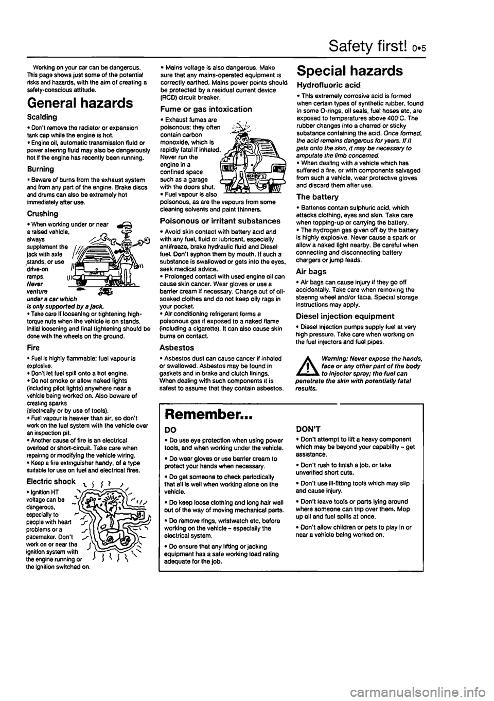
General hazards
Scalding • Don't remove the radiator or expansion tank cap while the engine is hot. • Engine oil, automatic transmission fluid or power steering fluid may also be dangerously hot if the engine has recently been running.
Burning • Beware of burns from the exhau3t system and from any part of the engine. Brake discs and drums can also be extremely hot immediately after use.
Crushing • When working under or near a raised vehicle. ~ always supplement the ' ' -jack with axle stands, or use ... drive-on i'j ramps. kr Never venture ™ under
a
car
vv/j/ch
Is only supported by a jack. • Take card if loosening or tightening high-torque nuts when the vehicle is on stands. Initial loosening and final tightening should be done with the wheels on the ground.
Fire • Fuel Is highly flammable; fuel vapour is explosive. • Don't (et fuel spill onto a hot engine. • Do not smoke or allow naked lights (including pilot lights) anywhere near a vehicle being worked on. Also beware of creating sparks (electrically or by use of toots). • Fuel vapour is heavier than air, so don't work on the fuel system with the vehicle over an inspection pit. • Another cause of fire is an electrical overload or short-circuit. Take care when repainng or modifying the vehicle wiring. • Keep a fire extinguisher handy, of a type suitable for use on fuel and electrical fires.
Electric shock x ^ ^ ? , • Ignition HT _ " voltage can be ^ dangerous, ~ especially to > people with heart problems or a pacemaker. Don't work on or near the f^ ignition system with fT") the engine running or ' J ' J the Ignition switched on.
• Mains voltage is also dangerous. Make sure that any mains-operated equipment is correctly earthed. Mains power points should be protected by a residual current device (RCD) circuit breaker.
Fume or gas intoxication • Exhaust fumes are poisonous: they often contain carbon monoxide, which is rapidly fatal if inhaled. Never run the engine in a confined space such as a garage with the doors shut, • Fuel vapour is also poisonous, as are the vapours from some cleaning solvents and paint thinners.
Poisonous or irritant substances • Avoid skin contact with battery acid and with any fuel, fluid or lubricant, especially antifreeze, brake hydraulic fluid and Diesel fuel. Don't syphon them by mouth. If such a substance is swallowed or gets into the eyes, seek medical advice. « Prolonged contact with used engine oil can cause skin cancer. Wear gloves or use a barrier cream If necessary. Change out of oll-soaked clothes and do not keep oily rags in your pocket. • Air conditioning refrigerant forms a poisonous gas if exposed to a naked flame {including a cigarette). It can also cause skin burns on contact.
Asbestos • Asbestos dust can cause cancer if inhaled or swallowed. Asbestos may be found In gaskets and in brake and clutch linings. When dealing with soch components It is safest to assume that they contain asbestos.
Special hazards
Hydrofluoric acid • This extremely corrosive acid is formed when cerlam types of synthetic rubber, found In some O-rings, oil seals, fuel hoses etc. are exposed to temperatures above 400;C. The rubber changes into a charred or sticky substance containing the acid. Once formed, the acid remains dangerous for years, tfit gets onto the skin, it may be necessary to amputate the limb concerned. • When dealing with a vehicle which has suffered a fire, or with components salvaged from such a vehicle, wear protective gloves and discard them after use.
The battery • Batteries contain sulphuric acid, which attacks clothing, eyes and skin. Take care when topping-up or carrying the battery. • The hydrogen gas given off by the battery is highly explosive. Never cause a spark or allow a naked light nearby. Be careful when connecting and disconnecting battery chargers or jump leads.
Air bags • Air bags can cause injury if they go off accidentally. Take care when removing the steenng wheel and/or facia. Special storage instructions may apply.
Diesel injection equipment • Diesel injection pumps supply fuel at very high pressure. Take care when working on the fuel injectors and fuel pipes.
A
Warning: Never expose the hands, face or any otfterpart of the body to injector spray; the fuel can penetrate the skin with potentially fatal results.
Remember...
DO • Do use eye protection when using power tools, and when working under the vehicle. • Do wear gloves or use barrier cream to protect your hands when necessary. • Do get someone to check periodically that all is well when working alone on the vehicle. • Do keep loose clothing and long hair well out of the way of moving mechanical parts. • Do remove rings, wrtstwatch etc. before working on the vehicle - especially the electrical system, • Do ensure that any lifting or jacking equipment has a safe working load rating adequate for the job.
DON'T • Don't attempt to lift a heavy component which may be beyond your capability - get assistance. • Don't rush to finish a job. or take unverified short cuts. • Don't use ill-fitting toots which may slip and cause injury. • Don't leave tools or parts lying around where someone can trip over them. Mop up oil and fuel spills at once. • Don't allow children or pets to play In or near a vehicle being worked on.
Page 7 of 225
o.6 Roadside repairs
The following pages are Intended to help In dealing with common roadside emergencies and breakdowns. You will find more detailed fault finding information at the back of the manual, and repair Information In the main chapters.
If your car won't start
and the starter motor
doesn't turn
If your car won't start
even though the starter
motor turns as normal
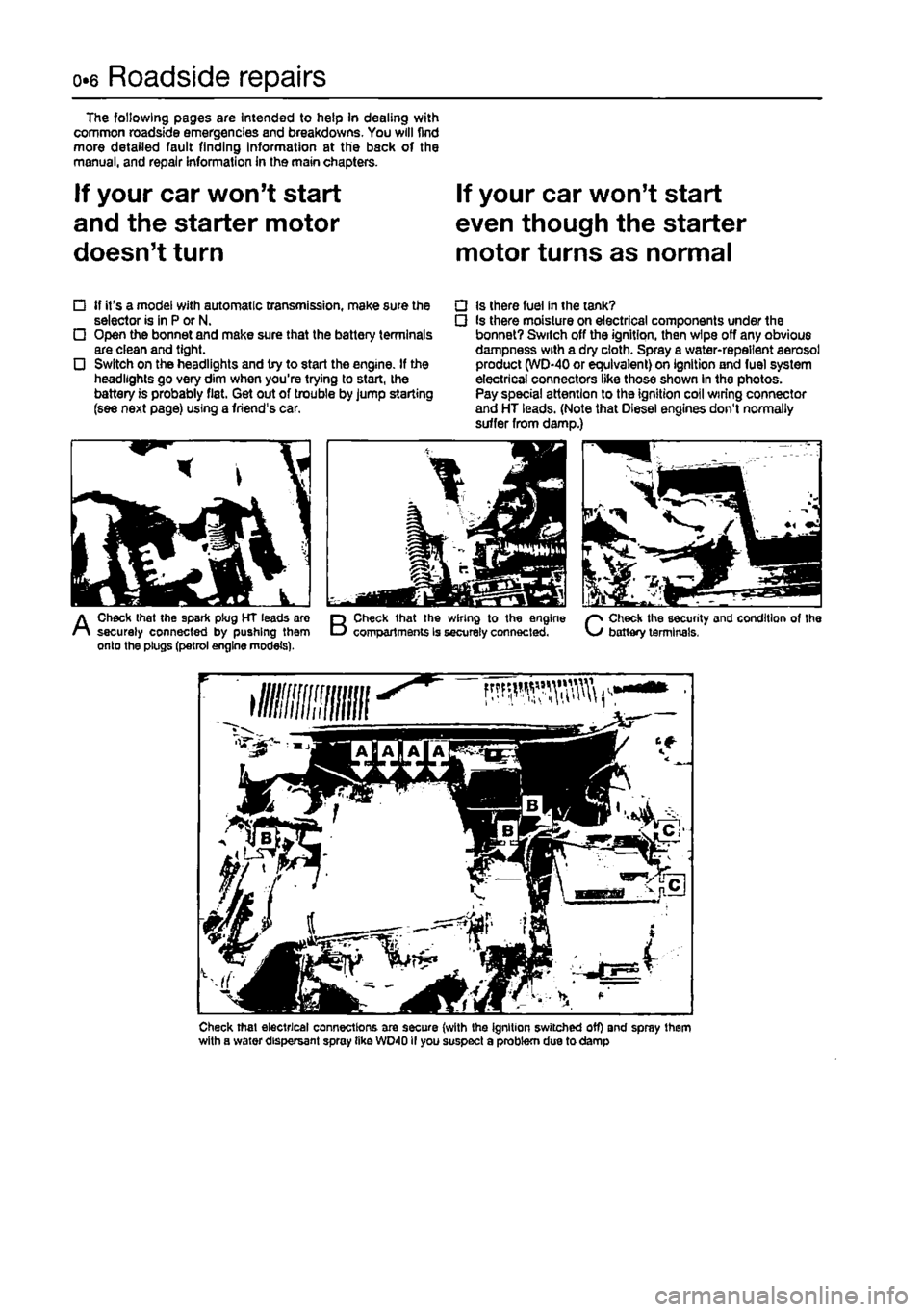
tf it's a model with automatic transmission, make sure the selector is in P or N. Open the bonnet and make sure that the battery terminals are clean and tight. Switch on the headlights and try to start the engine. If the headlights go very dim when you're trying to start, the battery is probably flat. Get out of trouble by Jump starting (see next page) using a friend's car.
• Is there fuel In the tank? • Is there moisture on electrical components under the bonnet? Switch off the ignition, then wipe off any obvious dampness with a dry cloth. Spray a water-repellent aerosol product (WD-40 or equivalent) on ignition and fuel system electrical connectors like those shown in the photos. Pay special attention to the ignition coil wiring connector and HT leads. (Note that Diesel engines don't normally suffer from damp.)
A
Check that the spark plug HT leads are securely connected by pushing them onto the plugs (petrol engine models).
B
Check that the wiring to the engine compartments is securely connected.
C
Check the security and condition of the battery terminals,
Check that electrical connections are secure (with the ignition switched off) and spray them with a water dispersant spray tike WD40II you suspect a problem due to damp
Page 22 of 225
Maintenance schedule - petrol models 1A.3
The maintenance Intervals in this manual are provided with the assumption that you, not the dealer, will be carrying out the work. These axe the minimum maintenance intervals recommended by us for vehicles driven daily.
if you wish to keep your vehicle in peak condition at all times, you may wish to perform some of these procedures more often. We encourage frequent maintenance, because it enhances the efficiency.
performance and resale value of your vehicle. When the vehicle Is new, it should be serviced by a factory-authorised dealer service department, In order to preserve the factory warranty.
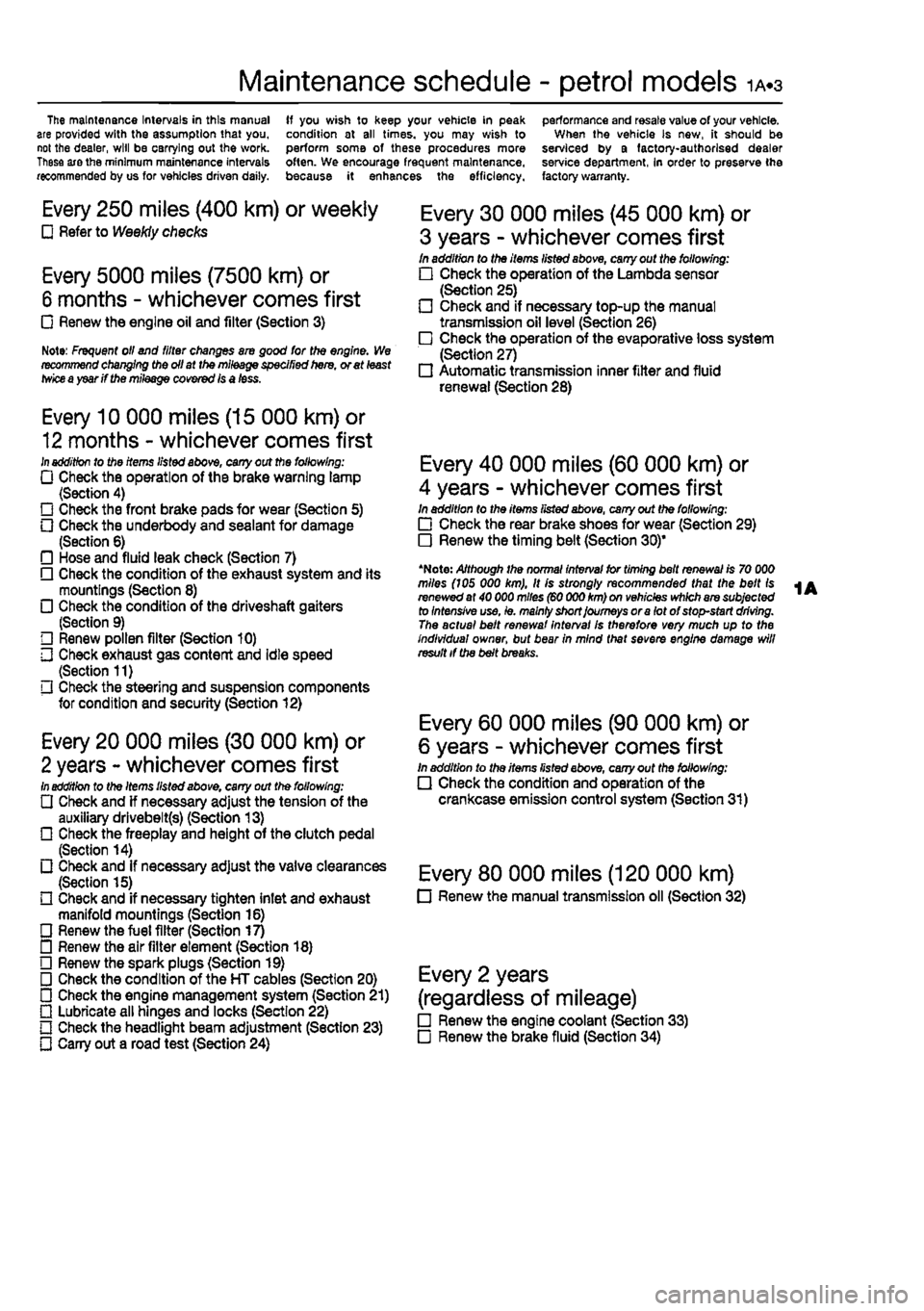
Every 250 miles (400 km) or weekly Q Refer to Weekly checks
Every 5000 miles (7500 km) or
6 months - whichever comes first • Renew the engine oil and filter (Section 3)
Note: Frequent oil and fitter changes am good tor the engine. We recommend changing the oil at the mileage specified here, or at least
twice
a year if the mileage covered Is a less.
Every 10 000 miles (15 000 km) or
12 months - whichever comes first
In
addition to the items listed above, cany out the following: Q Check the operation of the brake warning lamp (Section 4) • Check the front brake pads for wear (Section 5) • Check the underbody and sealant for damage (Section 6) • Hose and fluid leak check (Section 7) • Check the condition of the exhaust system and its mountings (Section 8) • Check the condition of the driveshaft gaiters (Section 9) • Renew pollen filter (Section 10) • Check exhaust gas content and idle speed (Section 11) • Check the steering and suspension components for condition and security (Section 12)
Every 20 000 miles (30 000 km) or
2 years - whichever comes first
In
addition to the Items listed above, carry out the following: • Check and if necessary adjust the tension of the auxiliary drlvebelt(s) (Section 13) • Check the freeplay and height of the clutch pedal (Section 14) • Check and if necessary adjust the valve clearances (Section 15) HI Check and if necessary tighten inlet and exhaust manifold mountings (Section 16) • Renew the fuel filter (Section 17) D Renew the air filter element (Section 18) O Renew the spark plugs (Section 19) • Check the condition of the HT cables (Section 20) • Check the engine management system (Section 21) Q Lubricate all hinges and locks (Section 22) O Check the headlight beam adjustment (Section 23) • Carry out a road test (Section 24)
Every 30 000 miles (45 000 km) or
3 years - whichever comes first In addition to the items listed above, cany out the following: • Check the operation of the Lambda sensor (Section 25) • Check and if necessary top-up the manual transmission oil level (Section 26) • Check the operation of the evaporative loss system (Section 27) • Automatic transmission inner filter and fluid renewal (Section 28)
Every 40 000 miles (60 000 km) or
4 years - whichever comes first In addition to the items fisted above, carry out the following: • Check the rear brake shoes for wear (Section 29) • Renew the timing belt (Section 30)"
*Noto: Although the normal interval for timing belt renewal is 70 000 miles (105 000 km), It is strongly recommended that the belt Is renewed at 40 000 miles (60 000 km) on vehicles which are subjected to Intensive use, ie. malniy short Journeys or a let of stop-start driving. The actual belt renewal Interval Is therefore very much up to the individual owner, but bear in mind that severe engine damage will result if the belt breaks.
Every 60 000 miles (90 000 km) or
6 years - whichever comes first in addition to the items listed above, cany out the following: • Check the condition and operation of the crankcase emission control system (Section 31)
Every 80 000 miles (120 000 km) • Renew the manual transmission oil (Section 32)
Every 2 years
(regardless of mileage) • Renew the engine coolant (Section 33) • Renew the brake fluid (Section 34)
Page 32 of 225
Every 20 000 miles - petrol models 1A.13
20 Ignition system check
81
21 Engine management system check
A
Warning: Voltages produced by an electronic ignition system are considerably higher than those produced by conventional ignition systems. Extreme care must be taken when working on the system with the Ignition switched on. Persons with surgically-Implanted cardiac pacemaker devices should keep well clear of the ignition circuits, components and test oquipment. 1 The ignition system components should be checked for damage or deterioration as follows.
General component check 2 The spark plug (HT) leads should be checked whenever new spark plugs are fitted. 3 Pull the leads from the plugs by gripping
the end
fitting, not the lead, otherwise the lead connection may be fractured.
Ensure that the leads are i numbered before removing i them, to avoid confusion when refitting
4 Check Inside the end fitting for signs of corrosion, which will look like a white crusty powder. Push the end fitting back onto the spark plug, ensuring that it is a tight fit on the plug. if not, remove the lead again and use pliers to carefully crimp the metal connector inside the end fitting until it fits securely on the
end
of the spark plug. 5 Using a clean rag, wipe Ihe emlre length of the lead to remove any built-up dirt and grease. Once the lead is clean, check for bums, cracks and other damage. Do not bend the lead excessively, nor pull the lead lengthways - the conductor inside might break. 6 Disconnect the other end of the lead from the ignition coll. Again, pull only on the end fitting. Check for corrosion and a tight fit in the
same
manner as the spark plug end. Refit the bad securely on completion. 7 Check the remaining leads one at a time, in
ihe same
way. 8 if new spark plug (HT) leads are required, purchase a set for your specific car and engine. 9 Even with the ignition system In first-class condition, some engines may still occasionally experience poor starting attributable to damp ignition components. To disperse moisture, a water-dispersant aerosol should be liberally
Ignition timing -
check
and adjustment 10 Check the ignition timing as described In Chapter 58.
1 This check is part of the manufacturer's maintenance schedule, and Involves testing Ihe engine management system using special dedicated test equipment. Such testing will allow the test equipment to read any fault codes stored in the electronic control unit memory. 2 Unless a fault is suspected, this test te not essential, although it should be noted that it is recommended by the manufacturers. 3 If access to suitable test equipment is not possible, make a thorough check of all ignition, fuel and emission control system components, hoses, and wiring, for security and obvious signs of damage. Further details of the fuet system, emission control system and ignition system can be .found In the relevant parts of Chapters 4 and 5.
22 Hinge and lock lubrication %
1
1 Lubricate the hinges of the bonnet, doors and tailgate with a light general-purpose oil. Similarly, lubricate ail latches, locks and lock strikers. At the same time, check the security and operation of all the locks, adjusting them If necessary (see Chapter 11). 2 Lightly lubricate the bonnet release mechanism and cable with a suitable grease.
23 Headlight beam adjustment % & ^
1 Accurate adjustment of the headlight beam is only possible using optical beem-setting equipment, and this work should therefore be carried out by a Fiat dealer or service station with the necessary facilities. In an emergency, however, the following procedure will provide an acceptable light pattern. 2 Position the car on a level surface with tyres correctly inflated, approximately 10 metres in front of. and at right-angles to, a wall or garage door, 3 Draw a horizontal line on the wall or door at headlamp centre height. Draw a vertical line corresponding to the centre line of the car, then measure off a point either side of this, on the horizontal line, corresponding with the headlamp centres. 4 Switch on the main beam and check that the areas of maximum illumination coincide with the headlamp centre marfcs on Ihe wall, if not. turn the adjustment screw located on the upper inside edge of the headlight unit to adjust the beam laterally, and the adjustment screw located on the upper outside edge of the headlight unit to adjust the beam
vertically. On models with electric headlight adjustment, make sure that it is set at its basic setting before making the adjustment.
24 Road test
Instruments and electrical equipment 1 Check the operation of all Instruments and electrical equipment. 2 Make sure that all instruments read correctly, and switch on all electrical equipment in turn, to check that it functions properly.
Steering and suspension 3 Check for any abnormalities in the steering, suspension, handling or road feel. 4 Drive the vehicle, and check that there are no unusual vibrations or noises. 5 Check that the steering feels positive, with no excessive sloppiness, or roughness, and check for any suspension noises when cornering and driving over bumps.
Drivetrain 6 Check the performance of the engine, clutch (where applicable), transmission and driveshafts. 7 Listen for any unusual noises from the engine, clutch and gearbox/transmission. 8 Make sure that the engine runs smoothly when Idling, and that there Is no hesitation when accelerating. 9 Check that, where applicable, the clutch action Is smooth and progressive, that the drive is taken up smoothly, and that the pedal travel is not excessive. Also listen for any noises when the clutch pedal is depressed. 10 On manual gearbox models, check that all gears can be engaged smoothly without noise, and that the gear lever action is not abnormally vsgue or notchy. 11 On automatic transmission models, check that all Ihe gear positions can be selected with the vehicle at rest, if any problems are found, they should be referred to a Flat dealer. 12 Listen for a metallic clicking sound from the front of the vehicle, as the vehicle is driven slowly in a circle with the steering on full-lock. Carry out this check in both directions. If a clicking noise is heard, this Indicates wear in a drtveshaft joint, In which case renew the joint if necessary.
Check the braking system 13 Make sure that the vehicle does not pull to one side when braking, and that the wheels do not lock prematurely when braking hard. 14 Check that there is no vibration through the steering when braking. 15 Check that the handbrake operates correctly without excessive movement of the lever, and that It holds the vehicle stationary on a slope.
Page 35 of 225
ia.16 Every 2 years - petrol models
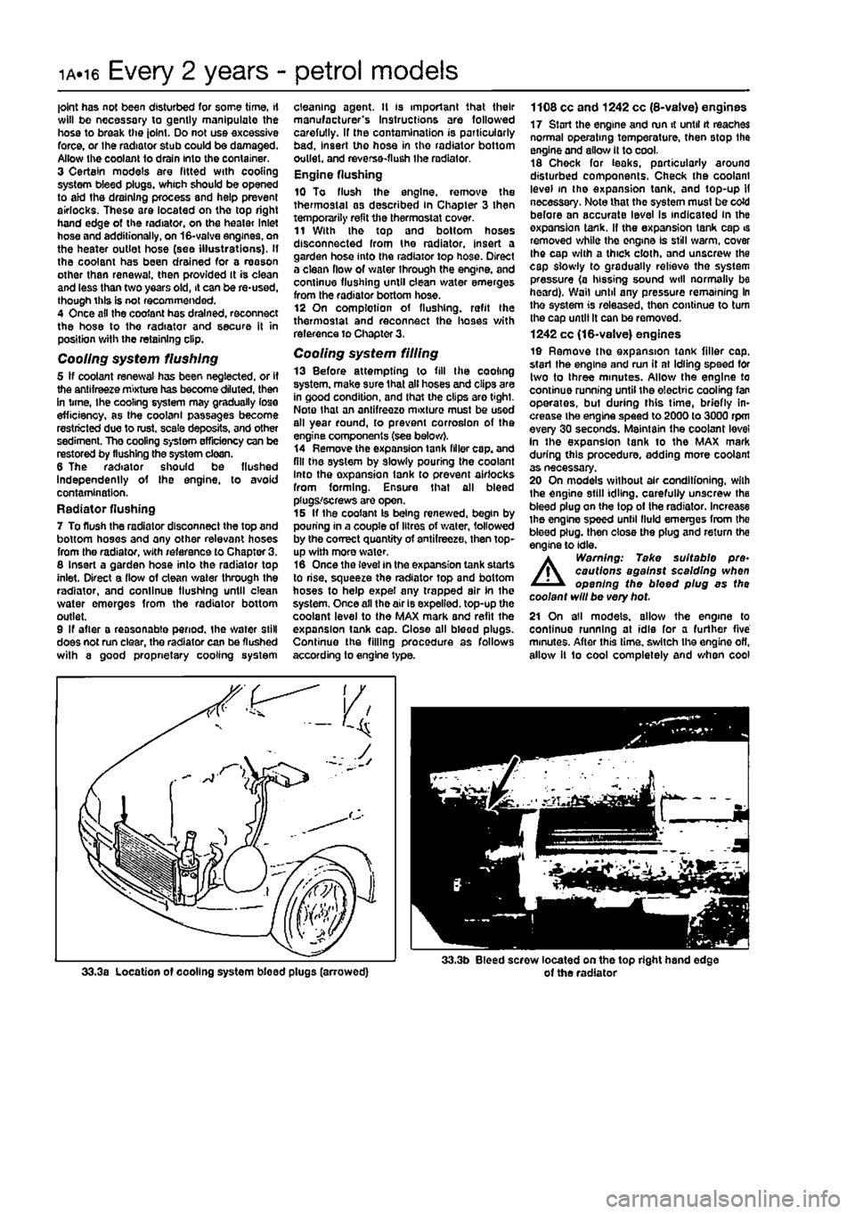
joint has not been disturbed for some time, if will bo necessary to gently manipulate the hose to break the joint. Do not use excessive force, or the radiator stub could be damaged. Allow the coolant to drain Into the container. 3 Certain models are fitted with cooling system bleed plugs, which should be opened to aid the draining process and help prevent airlocks. These are located on the top right hand edge of the radiator, on the heater Inlet hose and additionally, on 16-valve engines, on the heater outlet hose (see illustrations). If the coolant has been drained for a reason other than renewal, then provided It is ciean and less than two years old, it can be re-used, though this is not recommended. 4 Once ail the coofant has drained, reconnect the hose to the radiator and secure it in position with the retaining clip.
Cooling system flushing 5 If coolant renewal has been neglected, or If the antifreeze mixture has become diluted, then in time, Ihe cooling system may gradually lose efficiency, as the coolant passages become restricted due to rust, scale deposits, and other sediment. The cooling system efficiency can be restored by flushing the system clean. 6 The radiator should be flushed Independently of the engine, to avoid contamination. Radiator flushing 7 To flush the radiator disconnect the top and bottom hoses and any other relevant hoses from the radiator, with reference to Chapter 3. 8 Insert a garden hose into the radiator top inlet. Direct a flow of clean v/ater through the radiator, and continue flushing until clean water emerges from the radiator bottom outlet. 9 If after a reasonable period, the water still does not run clear, the radiator can be flushed wilh a good propnetary cooling system
cleaning agent. It is important that their manufacturer's Instructions are followed carefully. If the contamination is particularly bad, insert the hose in the radiator bottom outlet, and reverse-flush the radiator. Engine flushing 10 To flush the engine, remove the thermostat as described In Chapter 3 then temporarily refit the thermostat cover. 11 With the top and bottom hoses disconnected from the radiator, insert a garden hose into the radiator top hose. Direct a clean flow of water through the engine, and continue flushing until clean water emerges from the radiator bottom hose. 12 On complotion of flushing, refit the thermostat and reconnect the hoses with reference to Chapter 3,
Cooling system filling 13 Before attempting to fill the cooling system, make sure that all hoses and clips are in good condition, and that the clips are tight. Note that an antifreezo mixture must be used all year round, to prevent corrosion of the engine components (see below). 14 Remove the expansion tank filler cap. and fill the system by slowly pouring the coolant Into the oxpansion lank to prevent airlocks from forming. Ensure that all bleed plugs/screws are open. 15 If the coolant Is being renewed, begin by pouring in a couple of litres of v/ater, followed by the correct quantity of antifreeze, then top-up with more water. 16 Once the level in the expansion tank starts to rise, squeeze the radiator top and bottom hoses to help expel any trapped air In the system. Once all the air is expelled, top-up the coolant level to the MAX mark and refit the expansion tank cap. Close all bleed plugs. Continue the filling procedure as follows according to engine type.
1108 cc and 1242 cc (8-vaive) engines 17 Start the engine and run it until tt reaches normal operating temperature, then stop the engine and allow it to cool. 18 Chock for teaks, particularly around disturbed components. Check the coolant level in the expansion tank, and top-up H necessary. Note that the system must be coW before an accurate level Is indicated in the oxpansion tank. If the expansion tank cap is removed while the engine Is still warm, cover Ihe cap with a thick cloth, and unscrew the cap slowly to gradually relieve the system pressure (a hissing sound will normally be heard). Wall until any pressure remaining In the system is released, then continue to turn the cap until It can be removed. 1242 cc (16-valve) engines 19 Remove the expansion tank filler cap. start the engine and run it at Idling speed for two to three minutes. Allow the engine to continue running until the electric cooling fan operates, but during this time, briefly in-crease the engine speed to 2000 to 3000 rpm every 30 seconds. Maintain the coolant level in the expansion tank to the MAX mark during tliis procedure, adding more coolant as necessary. 20 On models without air conditfoning, wilh the engine still idling, carefully unscrew the bleed plug on the top of the radiator. Increase the engine speed until fluid emerges from the bleed plug, then close the plug and return the engine to idle.
A
Warning: Take suitable pre-cautions against scalding when opening the bleed plug as the coolant will be very hot. 21 On all models, allow the engine to continue running at idle for a further five minutes. After this time, switch the engine ofl, allow it 1o cool completely and when cool
Page 39 of 225
Maintenance schedule - diesel models 1B.3
The mamtenance intervals in this manual are provided with the assumption that you. reI ihe dealer, will be carrying out the work.
These
are the minimum maintenance intervals recommended by us for vehicles driven daily.
ff you wish to keep your vehicle In peak condition at all times, you may wish to perform some of these procedures more often. We encourage frequent maintenance, because it enhances the efficiency.
performance and resale value of your vehicle. When the vehicle Is new, it should be serviced by a factory-authorised dealer service department, in order to preserve the factory warranty.
Every 250 miles (400 km) or weekly O Refer to Weekly checks
Every 5000 miles (7500 km) or
6
months - whichever comes first • Renew the engine oil and filter (Section 3) P Drain any water from the fuel filter (Section 4)
Every 10 000 miles (15 000 km) or
12
months - whichever comes first ill addition lo tho Items listed above, cany out the following; D Check the operation of the brake warning lamp J (Section 5) Check the front brake pads for wear (Section 6) :-G Check the underbody and sealant for damage j" (Section 7) n Hose and fluid leak check (Section 8) 0 Check the condition of the exhaust system and its 1 mountings (Section 9) -D Check the condition of the driveshaft gaiters ", (Section 10) O Check and adjust the idle speed (Section 11) ;0 Renew (he fuel filter (Section 12) J] Renew the air filter element (Section 13) L) Renew the pollen filter (Section 14) •• Check the steering and suspension components • for condition and security (Section 15)
Every 20 000 miles (30 000 km) or
2
years - whichever comes first In addition to the Items listed above, cany out the following: (P Check and if necessary adjust the tension of the auxiliary drlvebeltfs) (Section 16) '• Check the freeplay and height of the clutch pedal " (Section 17) D Check and if necessary adjust the valve clearances (Section 18) Lubricate all hinges and locks (Section 19) • Check the headlight beam adjustment (Section 20) O Cany out a road test (Section 21)
Every 30 000 miles (45 000 km) or
3 years - whichever comes first In addition to the Items listed above, cany out the following: • Check and if necessary top-up the manual transmission oil level (Section 22)
Every 40 000 miles (60 000 km) or
4 years - whichever comes first In addition to the items listed above, cany out the following: • Check the rear brake shoes for wear (Section 23) • Renew the timing belt (Section 24)'
•Note: Although the normal interval for timing belt renewal is 70 000 miles (ids 000 km), it is strongly recommended that the belt Is renewed at 40 000 miles (60 000 km) on vehicles which are subjected to intensive use, le. mainly short Journeys or a lot of stop-start driving. The actual bait renewal interval Is therefore very much up to the Individual owner, but bear in mind that sevefe engine damage will result if the belt breaks.
Every 60 000 miles (90 000 km) or
6 years - whichever comes first In addition to the Items listed above, cany out the following: • Check the condition and operation of the emission control system components (Section 25)
Every 80 000 miles (120 000 km) • Renew the manual transmission oil (Section 26)
Every 2 years
(regardless of mileage) • Renew the engine coolant (Section 27) • Renew the brake fluid (Section 28)
Page 49 of 225
Maintenance procedures - diesel models 1B.13
Every 60 000 miles (90 000 km) or 6 years
Refer to Chapter 40. A full chock of the 26 Emissions control systems emissions control systems must be made by a check Fiat dealer.
Every 80 000 miles (120 000 km)
26 Manual transmission ,v->> oil renewal K
1 Pak the vehicle on a level surface, if possible over an inspection pit or on a ramp as the filer/level and drain plugs are accessed from
under the
engine compartment, ff necessary tack up Ihe vehicle and support on axle stands (see Jacking and
vehicle
support). 2
Wipe
clean the area around the filler/! a vol and vain plugs, which are situated on the front and bottom of the transmission (see Illustration}.
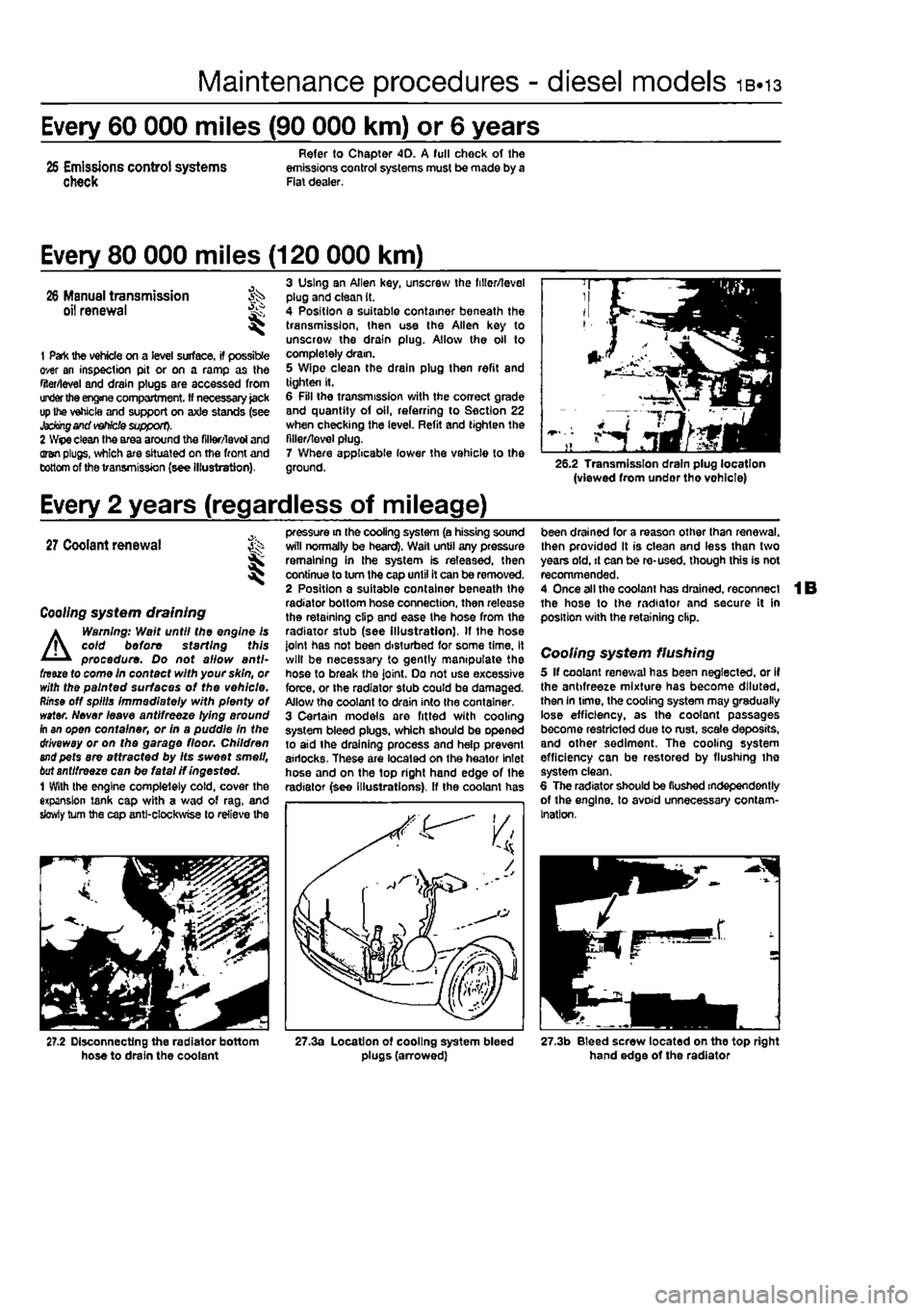
3 Using an Allen key, unscrew the fillor/level plug and clean it. 4 Position a suitable container beneath the transmission, then use the Allen key to unscrew the drain plug. Allow the oil to completely dram. 5 Wipe clean the drain plug then refit and tighten It. 6 Fill the transmission with the correct grade and quantity of oil, referring to Section 22 when checking the level. Refit and tighten the filler/level plug. 7 Where applicable lower the vehicle to the ground. 26.2 Transmission drain plug location (viewed from undor tho vohlcle)
Every 2 years (regardless of mileage)
27
Coolant renewal St I
Coo//ng system draining
A
Warning: Wait until the engine is coid before starting this procedure. Do not allow anti-fnue to come in contact with your skin, or with the painted surfaces of the vehicle.
Rinse
off spills immediately with plenty of water. Never leave antifreeze lying around fh an open container, or in a puddle in the driveway or on the garage floor. Children
and
pets are attracted by Its sweet smell,
bat
antifreeze can be fatal if ingested. 1 With the engine completely cold, cover the expansion tank cap with a wad of rag, and slowly turn the cap anti-clockwise to relieve the
pressure in the cooling system (a hissing sound will normally be heard). Wail until any pressure remaining in the system is released, then continue to turn the cap until it can be removed. 2 Position a suitable container beneath the radiator bottom hose connection, then release the retaining clip and ease the hose from the radiator stub (see Illustration), If the hose joint has not been disturbed for some time, it will be necessary to gently manipulate the hose to break the joint. Do not use excessive force, or the radiator stub could be damaged. Allow the coolant to drain into the container. 3 Certain models are fitted with cooling system bleed plugs, which should be opened to aid the draining process and help prevent airlocks. These are located on the heator Inlet hose and on the top right hand edge of the radiator (see Illustrations), ff the coolant has
been drained for a reason other than renewal, then provided It is clean and less than two years old, it can be re-used, though this is not recommended. 4 Once all the coolant has drained, reconnect the hose to the radiator and secure it in position with the retaining clip.
Cooling system flushing 5 If coolant renewal has been neglected, or if the antifreeze mixture has become diluted, then In time, the cooling system may gradually lose efficiency, as the coolant passages become restricted due to rust, scale deposits, and other sediment. The cooling system efficiency can be restored by flushing tho system clean. 6 The radiator should be (lushed independently of the engine, to avoid unnecessary contam-ination.
27.2 Disconnecting the radiator bottom hose to drain the coolant 27.3a Location of cooling system bleed plugs (arrowed) 27.3b Bleed screw located on the top right hand edge of the radiator
Page 53 of 225
2A*10 SOHC (8-valve) petrol engine in-car repair procedures
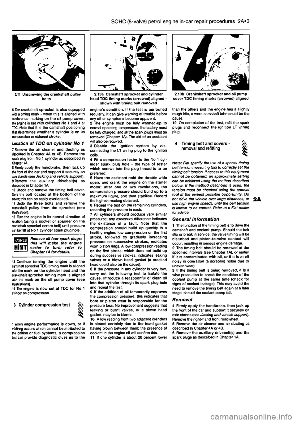
2.11 Unscrewing the crankshaft pulley bolts
6 Itae crankshaft sprocket Is also equipped •nth a timing mark - when this is aligned with 3relarence marking on the oil pump cover.
Hie
engine is set with cylinders No 1 and 4 at
TDC.
Note that it is the camshaft positioning that determines whether a cylinder is on its comcression or exhaust stroke.
Location
of TDC on cylinder No 1 7 Remove the air cleaner and ducting as descnbed in Chapter 4A or 4B. Remove the
spark
plug from No 1 cylinder as described in Chapter 1A. 8 Firmly apply the handbrake, then |ack up
the
front of the car and support it securely on iiia stands (see Jacking end vehicle support). 9 Remove the auxiliary drivebelt(s) as described in Chapter 1A. 10 Unbolt and remove the timing belt cover. Mole the bolt located at the bottom of the
coven
this can be easily overlooked. 11 Undo the three bolts and remove the crankshaft pulley from the sprocket (see {lustration). 12 Turn Ihe engine in its normal direction of rotation (using a socket or spanner on Ihe crankshaft sprocket centre bolt) until pressure an be felt at No
1
cylinder spark plug hole.
1 flfliyflg^ Remove all four spark plugs; "••"•1 this will make the engine HlNTl easier to turn; refer to Chapter 1A for details.
13 Continue turning the engine until the crahaft sprocket TDC timing mark is aligned with the mark on the cylinder head and the crankshaft sprocket timing mark is aligned with the mark on the oil pump cover (see ilustrations). 14 The engine is now set at TDC for No 1 cylinder on compression.
3 Cylinder compression test t ^
1 When engine performance Is down, or if misfiring occurs which cannot be attributed to tne ignition or fuei systems, a compression isst can provide diagnostic clues as to the
2.13a Camshaft sprocket and cylinder head TDC timing marks (arrowed) aligned -shown with timing belt removed engine's condition. II the test is performed regularly, it can give warning of trouble any other symptoms become apparent. 2 The engine must be fully warmed-up to normal operating temperature, the battery must be fufly charged, and all the spark plugs must be removed (Chapter 1A). The aid of an assistant will also be required. 3 Disable the ignition system by dis-connecting the LT wiring plug to the ignition coils. 4 Fit a compression tester to the No 1 cyl-inder spark plug hole - the type of tester which screws into the plug thread is to be preferred, 5 Have the assistant hold the throttle wide open, and crank the engine on the starter motor; after one or two revolutions, the compression pressure should build up to a maximum figure, and then stabilise. Record the highest reading obtained. 6 Repeat the lest on the remaining cylinders, recording the pressure in each. 7 All cylinders should produce very similar pressures; any excessive difference indicates the existence of a fault. Note that the compression should build up quickly in a healthy engine; low compression on the first stroke, followed by gradually increasing pressure on successive strokes, indicates worn piston rings. A low compression reading on the first stroke, which does not build up during successive strokes, indicates leaking valves or a blown head gasket (a cracked head could also be the cause). 8 If the pressure in any cylinder is very low. carry out the following test to isolate the cause. Introduce a teaspoonful of clean oil into that cylinder through its spark plug hole and repeat the test. 9 If the addition of oil temporarily improves the compression pressure, this indicates that bore or piston wear Is responsible for the pressure loss. No improvement suggests that leaking or burnt valves, or a biown head gasket, may be to blame. 10 A low reading from two adjacent cylinders is almost certainly due to the head gasket having blown between them; the presence of coolant in the engine oil will confirm this. 11 If one cylinder is about 20 percent lower
2.13b Crankshaft sprocket and oil pump cover TDC timing marks (arrowed) aligned
than the others and Ihe engine has a slightly rough idle, a worn camshaft lobe could be the cause. 12 On completion of the test, refit the spark plugs and reconnect the ignition LT wiring plug.
4 Timing belt and covers -removal and refitting ^
Note: Fiat specify the use of a special timing belt fens/on measuring toot to correctly set tho timing belt tension. If access to this equipment cannot be obtained, an approximate setting can be achieved using the method described below. It the method described is used, the tension must be checked using the special tool at the earliest possible opportunity. Do not drive the vehicle over large distances, or use high engine speeds, until the belt tension is known fo be correct. Refer to a Fiat dealer foradvSce.
General information 1 The function of the timing belt is to drive Ihe camshaft and coolant pump. Should the belt slip or break In service, the valve timing will be disturbed and piston-to-valvo contact will occur, resulting in serious engine damage, 2 The timing belt should be renewed ai the specified intervals (see Chapter 1A), or earlier if it is contaminated with oil. or if it is at all noisy in operation (a scraping noise due to uneven wear). 3 If the timing belt is being removed, it Is a wise precaution to check the condition of the coolant pump at the same time (check for signs of coolant leakage). This may avoid the need to remove the timing belt again at a later stage, should the coolant pump fall.
Removal 4 Firmly apply the handbrake, then jack up the front of the car and support it securely on axle stands (see Jacking and vehicle support). Remove the right-hand front road wheel. 5 Remove the air cleaner and air ducting as described in Chapter 4A or 46. 6 Remove the auxiliary drivebelt(s) and the spark plugs as described in Chapter 1A.
2A
Page 64 of 225
2B*4 DOHC (16-valve) petrol engine in-car repair procedures
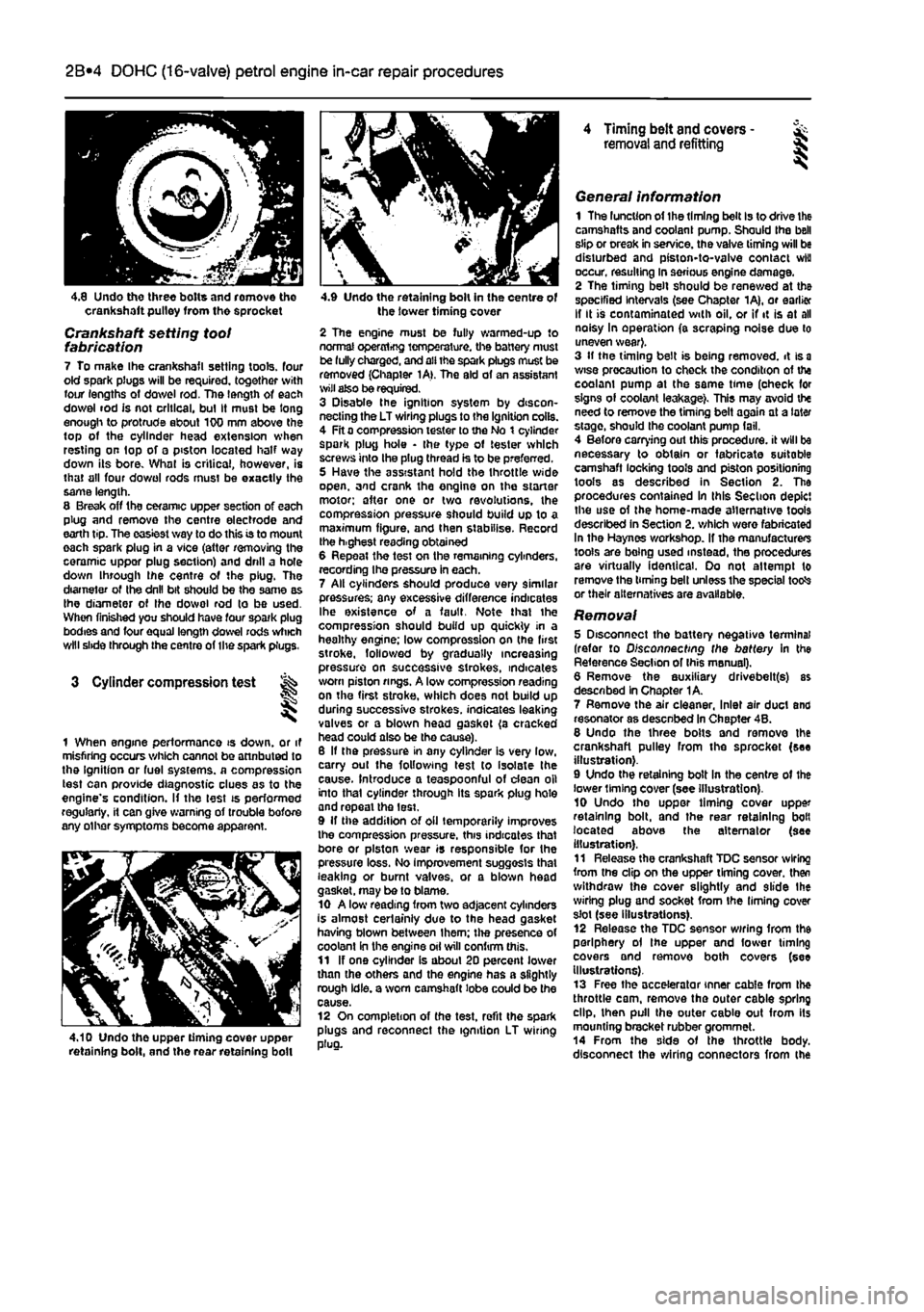
4.8 Undo three bolts and romove tho crankshaft pulley from the sprocket
Crankshaft setting toot fabrication 7 To make Ihe crankshafl setting tools, four old spark plugs will be required, together with four lengths of dowel rod. The length of each dowel rod is not critical, bul It must be long enough to protrude about 100 mm above the top of the cylinder head extension when resting on top of a piston located half way down its bore. What is critical, however, is that all four do wo I rods must be exactly the same length. 8 Break off the ceramic upper section of each plug and remove the centre electrode and earth tip. The easiest way to do this is to mount each spark plug in a vice (attar removing the ceramic uppor plug section) and drill a hole down through ihe centre of the plug. The diameter of Ihe drill bit should be the same as Ihe diameter of Ihe dowol rod to be used. When finished you should have four spark plug bodies and four equal length dowel rods which will slide through the centre of the spark plugs.
3 Cylinder compression test
1 When engine performance is down, or it misfiring occurs which cannot be attnbuted to the Ignition or fuel systems, a compression test can provide diagnostic clues as to the engine's condition. If the lest is performed regularly, it can give warning of trouble bofore any other symptoms become apparent.
4.10 Undo the upper timing cover upper retaining bolt, and the rear retaining boll
4.9 Undo the retaining bolt in the centre of the lower timing cover
2 The engine must be fully warmed-up to normal operxrtrfjg temperature, the battery must be fully charged, and all the spark plugs muse be removed (Chapter 1A>. The aid of an assistant wilt also be required. 3 Disable the ignition system by discon-necting the LT wiring plugs to the Ignition coils. 4 Fit a compression tester to the No t cylinder spark plug hole • the type of tester which screws into the plug thread is to be preferred. 5 Have the assistant hold the throttle wide open, and crank the engine on the starter motor; after one or two revolutions, the compression pressure should build up to a maximum figure, and then stabilise. Record the h.ghest reading obtained 6 Repeat the test on the remaining cylinders, recording Ihe pressure in each. 7 All cylinders should produce very similar pressures; any excessive difference indicates Ihe existence of a fault. Note that the compression should build up quickly in a healthy engine; low compression on (he first stroke, followed by gradually increasing pressure on successive strokes, indicates worn piston rings. A low compression reading on the first stroke, which does not build up during successive strokes, indicates leaking valves or a blown head gasket (a cracked head could also be tho cause). 6 If the pressure in any cylinder is very low, carry out the following test to isolate the cause. Introduce a teaspoonful of dean oil into that cylinder through its spark plug hole and repeal the lest. 9 If the addition of oil temporarily improves the compression pressure, this indicates that bore or piston wear is responsible for the pressure loss. No improvement suggests that leaking or burnt valves, or a blown head gasket, may be to blame. 10 A low reading from two adjacent cylinders is almost certainly due to the head gasket having blown between Ihem; the presence of coolant in the engine oil will confirm this. 11 If one cylinder is about 20 percent lower than the others and the engine has a slightly rough idle, a worn camshaft lobe could be the cause. 12 On completion of the test, refit the spark plugs and reconnect the ignition LT wiring plug.
4 Timing belt and covers -removal and refitting §
General information 1 The luncUon of the timing belt Is to drive the camshafts and coolant pump. Should the bell slip or creak in service, the valve timing will be disturbed and piston-to-valve contact wiu occur, resulting in serious engine damage. 2 The timing belt should be renewed at the specified Intervals (see Chapter 1A), or earlier If It is contaminated with oil, or if it is at all noisy In operation (a scraping noise due to uneven wear}. 3 If the timing belt is being removed, it is
a
wise precaution to check the condition of the coolam pump at the same time (oheck for signs of coolant leakage). This may avoid the need to remove the timing belt again at a later stage, should the coolant pump fail. 4 Before carrying out this procedure, it will be necessary to obtain or fabricate suitable camshaft locking tools and piston positioning tools as described in Section 2. The procedures contained In this Section depict the use of the home-made alternative tools described in Section 2. which were fabricated In the Haynes workshop. If the manufacturers tools are being used instead, the procedures are virtually identical. Oo not attempt to remove the timing bell unless the special totfs or their alternatives are available.
Removal 5 Disconnect the battery negative terminal (refer to Disconnecting the battery in the Reference Section of Ihis manual). 6 Remove the auxiliary drivebelt(s) as described In Chapter 1A. 7 Remove the air cleaner, Inlet air duct and resonator as desenbed In Chapter 4B. 8 Undo the three bolts and remove the crankshaft pulley from the sprocket (see illustration). 9 Undo the retaining bolt In the centre of the lower liming cover (see illustration). 10 Undo tho uppor timing cover upper retaining bolt, and the rear retaining bolt located above the alternator (see illustration). 11 Release the crankshaft TDC sensor wiring from the clip on the upper timing cover, then withdraw the cover slightly and slide Ihe wiring plug and socket from the liming cover slot (see illustrations). 12 Release the TDC sensor wiring from the periphery ol the upper and fower timing covers and remove both covers (see Illustrations). 13 Free the accelerator inner cable from the throttle cam, remove the outer cable spring dip, then pull the outer cable out from its mounting bracket rubber grommet. 14 From the side of the throttle body, disconnect the wiring connectors from the
Page 71 of 225
DOHC (16-valve) petrol engine in-car repair procedures 2B*11
camshaft cover plate... 25 Locate the cam follower retaining tools in position and refit the cylinder head extension
as
described In Section 8.
10
Cylinder head - &
removal and
refitting S
Removal Note; The cylinder head bolts are of special
sekned
design and a Fiat tool should be
obtained
to unscrew them. A Ton key will not
JSt however
in practise It was found that a dose-httlng Alien key could be used as an itemative. 1 Drain the cooling system as described in Chapter 1A. 2 Remove the cylinder head extension as oescAbed
m
Section 8. 3 Disconnect the radiator hose from the thermostat housing on the left-hand end of
Ihe
cylinder head. 4 Disconnect the heater hose from the outlet
at the
rear of the cylinder head. 5 Disconnect the coolant temperature sensor md temperature gauge sensor wiring plugs
torn
the left-hand end of the cylinder head. 9 Undo the engine oil dipstick tube bracket retaining bolt and the two bolts securing the wing harness support clips to the inlet marriold lower section. 7 Undo Ihe retaining nuts and separate the ixhaust system front pipe from the exhaust manifold flange.
8
Check that nothing remains attached to the cinder head likely to impede removal. It Is assumed that the head will be removed complete with exhaust manifold and inlet manifold lower section. 9 Unscrew the cylinder head bolts half a turn K
e
time in the reverse order to that shown in (lustration 10.20a. When the bolts are free. «mwe them from their locations.. Id Lift the cylinder head from the block. If it is stuck tight rock the head to break the joint by mans of the manifolds. On no account drive
levers
into the gasket Joint, nor attempt to tap tf« head sideways, as it is located on positioning dowels. 11 Remove and discard the cylinder head gasket.
JK'
l^. 9.22b ... then apply RTV gasket sealant to the cover plate contact face 12 Refer to Chapter 20 for cylinder head dismantling and inspection procedures. Preparation for refitting 13 The mating faces of the cylinder head and cylinder block must be perfectly dean before refitting the head. Use a hard plastic or wooden scraper to remove all traces of gasket and carbon; also clean the piston crowns, Take particular care when cleaning the piston crowns as the soft aluminium alloy is easily damaged. Make sure that the carbon is not allowed to enter the oil and water passages -this Is particularly important for the lubncahon system, as carbon could block the oil supply to the engine's components. Using adhesive tape and paper, seal the water, oil and bolt holes in the cylinder block. To prevent carbon entering the gap between the pistons and bores, smear a little grease In the gap. After cleaning each piston, use a small brush to remove all traces of grease and carbon from the gap. then wipe away the remainder with a clean rag. Clean all the pistons in the same way. 14 Check the mating surfaces of the cylinder block and the cylinder head for nicks, deep scratches and other damage. If slight, they may be removed carefully with a file, but If excessive, machining may be the only alternative to renewal. If warpage of the cylinder head gasket surface Is suspected, use a straight-edge to check it for distortion. Refer to Part 0 of this Chapter if necessary. 15 Check the condition of the cylinder head bolts, and particularly their threads, whenever they are removed. Wash the bolts In a suitable
sequence
9.24 Lubricate the cam followers and place them in position in their respective bores solvent, and wipe them dry. Check each bolt for any sign of visible wear or damage, renewing them if necessary.
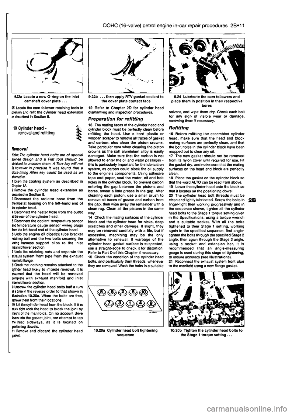
Refitting 18 Before refitting the assembled cylinder head, make sure that the head and block mating surfaces are perfectly clean, and that the bolt holes in the cylinder block have been mopped out to clear any oil, 17 The now gasket should not be removed from its nylon cover until required for use. Fit Ihe gasket dry, and make sure that the mating surfaces on the head and block are perfectly clean. 18 Place the gasket on the cylinder block so that the word ALTO can be read from above. 19 Lower the cylinder head onto the block so that it locates on the positioning dowel. 20 The cylinder head bolt threads must be clean and lightly lubricated. Screw the bolts in finger-tight then working progressively and in the sequence shown, lighten all the cylinder head bolts to the Stage 1 torquo setting given In the Specifications, using a torque wrench and a suitable socket. With all the bolts tightened to their Stage 1 setting, working again in the specified sequence, first angle-tighten the bolts through the specified Stage 2 angle, then again through the Stage 3 angle, using a socket and extension bar. It Is recommended that an angle-measuring gauge Is used during this stage ot tightening, to ensure accuracy (see Illustrations). 21 Reconnect the exhaust system front pipe to the manifold using a new flange gasket.
10.20b Tighten the cylinder head bolts to the Stago 1 torque setting ...