spark plugs replace FIAT PUNTO 1998 176 / 1.G Workshop Manual
[x] Cancel search | Manufacturer: FIAT, Model Year: 1998, Model line: PUNTO, Model: FIAT PUNTO 1998 176 / 1.GPages: 225, PDF Size: 18.54 MB
Page 31 of 225

1A.12
Every 20 000 miles - petrol models
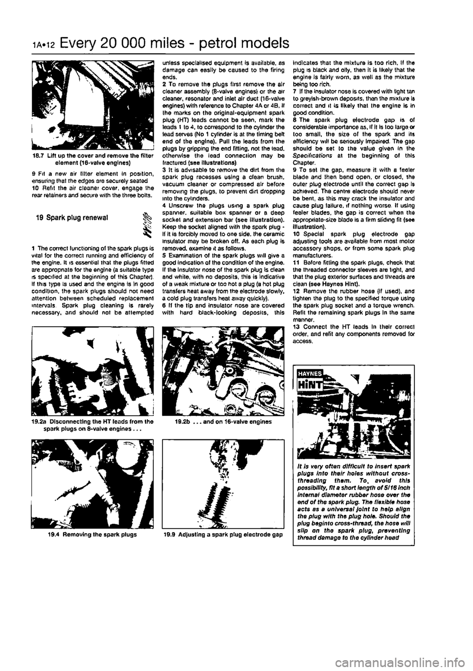
18.7 Lift up the cover and remove the filter element (18-va!ve engines) 9 Fit a new air (liter element In position, ensuring that the edges are securely seated 10 Refit the air cloaner cover, engage the rear retainers and secure with the three bolts.
19 Spark plug renewal
1 The correct functioning of the spark plugs is vital for the correct running and efficiency of the engine. It is essential that the plugs fitted are appropnate for the engine (a suitable type is specified at the beginning of this Chapter. If this type is used and the engine Is In good condition, the spark plugs should not need attention between scheduled replacement intervals Spark plug cleaning Is rarely necessary, and should not be attempted
19.2a Disconnecting tho HT leads from Iho spark plugs on 8-valve engines ...
19.4 Removing the spark plugs
unless specialised equipment Is available, as damage can easily be caused to the firing ends. 2 To remove the plugs first remove the air cleaner assembly (8-vaive engines) or the a»r cleaner, resonator and inlet air duct (16-valve engines) with reference to Chapter 4A or 4B. if the marks on the original-equipment spark plug (HT) leads cannot be seen, mark the leads 1 to 4, to correspond to the cylinder the lead serves (No 1 cylinder is at the timing belt end of the engine). Pull the leads from the plugs by gripping the end fitting, not the lead, otherwise the lead conneciion may be Iractured (see illustrations) 3 It is advisable to remove the dirt from the spark plug recesses using a clean brush, vacuum cleaner or compressed air before removing the plugs, to prevent dirt dropping into the cylinders. 4 Unscrew the plugs using a spark plug spanner, suitable box spanner or a deep socket and extension bar (see illustration). Keep the socket aligned with the spark plug • If it is forcibly moved to one side, the ceramic insulator may be broken off. As each plug is removed examine 4 as fallows. 5 Examination of the spark plugs will give a good Indication of the condition of the engine. If the Insulator nose of the spark plug Is clean and white, with no deposits, this is Indicative of a weak mixture or too hot a plug (a hot plug transfers heal away from the electrode slowly, a cold plug transfers heat away quickly). 6 If the tip and insulator nose are covered with hard black-looking deposits, this
19.2b ... and on 16-valve engines
19.9 Ad|ustlng a spark plug electrode gap
indicates that the mixture Is too rich. If the plug is black and oily, then It is likely that the engine is fairly worn, as well as the mixture being too rich. 7 If the Insulator nose is covered with light tan to greyish-brown deposits, then the mixture Is correct and it is likely that (he engine Is in good condition. 6 The spark plug electrode gap is of considerable importance as, if it Is too large or too small, the size of the spark and its efficiency will be seriously impaired. The gap should be set to the value given in the Specifications at the beginning of this Chapter. 9 To set the gap. measure it with a feeler blade and then bend open, or closed, the outer plug elect/ode until the correct gap l9 achieved. The centre electrode should never be bent, as this may crack the insulator and cause plug I allure, if nothing worse. If using feeler blades, the gap is correct when the appropriate-size blade is a firm sliding fit (see illustration). 10 Special spark plug electrode gap adjusting tools are available from most motor accessory shops, or from some spark plug manufacturers, 11 Before fitting the spark plugs, check that the threaded connector sleeves are tight, and that the plug exterior surfaces and threads are clean (see Haynes Hint). 12 Remove the rubber hose (If used), and tighten the plug to the specified torque using the spark plug socket and a torque wrench, Refit the remaining spark plugs In the same manner. 13 Connect the HT leads In their correct order, and refit any components removed for access.
It is very often difficult to insert spark plugs into their holes without cross-threading them. To, avoid this possibility, fit a short length of Si 16 Inch Internal diameter rubber hose over the end of the spark plug. The flexible hose acts as a universal Joint to help align the plug with the plug hole. Should the plug beginto cross-thread, the hose will slip on the spark plug, preventing thread damage to the cylinder head
Page 98 of 225

2D*10 Engine removal and overhaul procedures
05 Remove the brush holder assembly from the automatic transmission as described in Chapter 7B, Section 4. The brushes bear on the slip rings at the rear of the electro-magnetic clutch housing and they may be damaged when the transmission is removed. 86 Unscrew and remove the transmission-to-engine bolts then carefully draw the transmission away from the engine, resting It securely on wooden blocks. Collect the locating dowels If they are loose enough to be extracted, 87 If the oil pump driveshaft remains engaged with the crankshaft, remove it and reert Into the transmission to protect It from damage.
Connection 86 If the engine and transmission have not been separated, go to paragraph 104. Manual transmission models 89 Smear a little high-melting-point grease
on
the splines of the transmission input shaft. Do not use an excessive amount as there Is the risk of contaminating the clutch friction plate. 90 Carefully offer up the transmission to the engine cylinder block, guiding the input shaft through the clutch friction plate. 91 Refit the transmission-to-engine bolts and
the
single nut. hand^jghtenlng 1hem to secure the transmission in position. Note: Do not hghten them to force the engine and transmission together. Ensure that the beilhousing and cylinder block mating faces will butt together evenly without obstruction, before finally tightening the bolts and nut securely. Automatic transmission models 92 Check that the oil pump driveshaft is correctly engaged with the oil pump in the transmission. 93 Carefully offer up the transmission to Ihe rear of the engine and insert the oil pump driveshaft In the centre of the electro-magnetic clutch housing. Locate the transmission on the locating dowels then Insert the bolts and tighten them securely. 94 Refit the brush holder assembly to the automatic transmission with reference to Chapter 7B, Section 4. Petrol engines 96 Refit the transmission lower cover and tighten the bolts. 96 Locate the support bracket on the lower cover, then insert the bolts hand-tight. Also Insert the bolts securing the bracket lo the rear of Ihe cylinder block. With all the bolts Inserted, tighten them securely. 97 Refit the earth leads and tighten the bolts. Diesel engines 98 Refit the rpm sensor and tighten the bolts. 99 Insert the Intermediate shaft through the bracket then locate the dust boot on it and insert the Inner end in the transmission.
100 Refit and tighten the bolts securing the Intermediate shaft to the bracket on the rear of the cylinder block. 101 Refit the transmission lower cover and tighten the bolts. Ail models 102 Refit the starter motor (see Chapter 5A). 103 Refit the wiring harness to the components on the engine/transmission assembly making sure it is routed correctly.
Refitting 104 Locate the engine/transmission assembly beneath the engine compartment and attach the hoist to the lifting eyes. 105 Carefully lift the assembly up into the engine compartment taking care not to damage the surrounding components. 106 Reconnect the left-hand engine/trans-mission mounting to the body and tighten the bolts. 107 Reconnect Ihe right-hand engine mounting to the body and tighten the bolts. 108 Working beneath the vehicle, refit the rear engine mounting and tighten the bolts. 109 Disconnect the hoist from the engine and transmission lifting eyes and remove the hoist from under the vehicle. 110 The remainder of the refitting procedure is the direct reverse of the removal procedure, noting the following points:
a) Ensure that alf sections of the wiring harness follow their original routing; use new cable-ties to secure the harness In position, keeping it away from sources
of
heat and abrasion. b) On vehicles with manual transmission check and if necessary adjust the gearchenge cable and rod with reference to Chapter 7A. c) On vehicles with automatic transmission use new ro//p/ns fo secure the driveshafts to the transmission output stubs. Also check and if necessary adjust the kickdown end selector cables with reference to Chapter 78. d) Ensure that afi hoses are correctly routed and are secured with the correct hose clips, where applicable. If the hose clips cannot be used again; proprietary worm drive clips should be fitted
In
their place. e) Refill the cooling system as described in Chapter 1A or 18. f) Refill the engine with appropriate grades and quantities of oil (Chapter
1A
or 1B). g) Refit and adjust the auxiliary drivebelt(s) wfth reference fo Chapter 1A or 1B. h) Check and If necessary adjust the accelerator cable with reference to Chapter
AA,
48 or
AC.
i) When the engine is started for the first time, check for
air,
coolant, lubricant and fuel leaks from manifolds, hoses etc. If
the
engine has been overhauled, read
the
notes In Section 13 before attempting to starlit.
5 Engine overhaul • dismantling sequence
1 It is much easier to dismantle and work on the engine if it is mounted on a portable engine stand. These stands can often be hired from a tool hire shop. Before the engine is mounted on a stand, the flywheel should be removed, so that the stand bolts can be tightened Into the end of the cylinder block/crankcase. 2 If a stand Is not available, it Is possible to dismantle the engine with it blocked up on a sturdy workbench, or on the floor, Be very careful not to tip or drop the engine when working without a stand. 3 If you intend to obtain a reconditioned engine, all anclllarles must be removed first, to be transferred to the replacement engine (just as they will If you are doing a complete engine overhaul yourself). These components Include the following:
Petroi engines a) Power steering pump if removed with the engine (Chapter
10).
b) Alternator fmcluding mounting brackets) and starter motor (Chapter
SA).
c) The Ignition system and HT components including ail sensors, HT leads and
spark
plugs (Chapters 1A and
SB).
d) The fuel injection system components (Chapters A A and
AB).
e) All electrical switches, actuators and sensors, and the engine wiring harness (Chapters 4A, AB, SB). f) Inlet and exhaust manifolds (Chapters 4A, AB end
AD).
g) Engine oil dipstick and tube. h) Engine mountings (Chapter
2A).
i) Flywheef/driveptate (Chapter
2A).
j) Clutch components (Chapter
6)
- manual transmission. k) Electro-magnetic clutch components (Chapter 7B) - automatic transmission. I) Cooling system components (Chapter
3).
Diesei engines a) Power steering pump //removed with the engine (Chapter
10).
b) Alternator (Including mounting brackets) and starter motor (Chapter 5A). c) The glow plugfpre-heatlng system components (Chapter
SC).
d) Ait fuel system components, including the fuel injection pump, all sensors and actuators (Chapter
AC).
e) The vacuum pump. f) Ail electrical switches, actuators and sensors, and the engine wiring harness (Chapter 4C and 5C). g) Inlet and exhaust manifolds and, where applicable, the turbocharger (Chapter
AC
and 4D). h) The engine oil level dipstick and its tube. i) Engine mountings (Chapter
2C).