ventilation FIAT PUNTO 1999 176 / 1.G User Guide
[x] Cancel search | Manufacturer: FIAT, Model Year: 1999, Model line: PUNTO, Model: FIAT PUNTO 1999 176 / 1.GPages: 225, PDF Size: 18.54 MB
Page 142 of 225

Fuel system - diesel models
4C*3
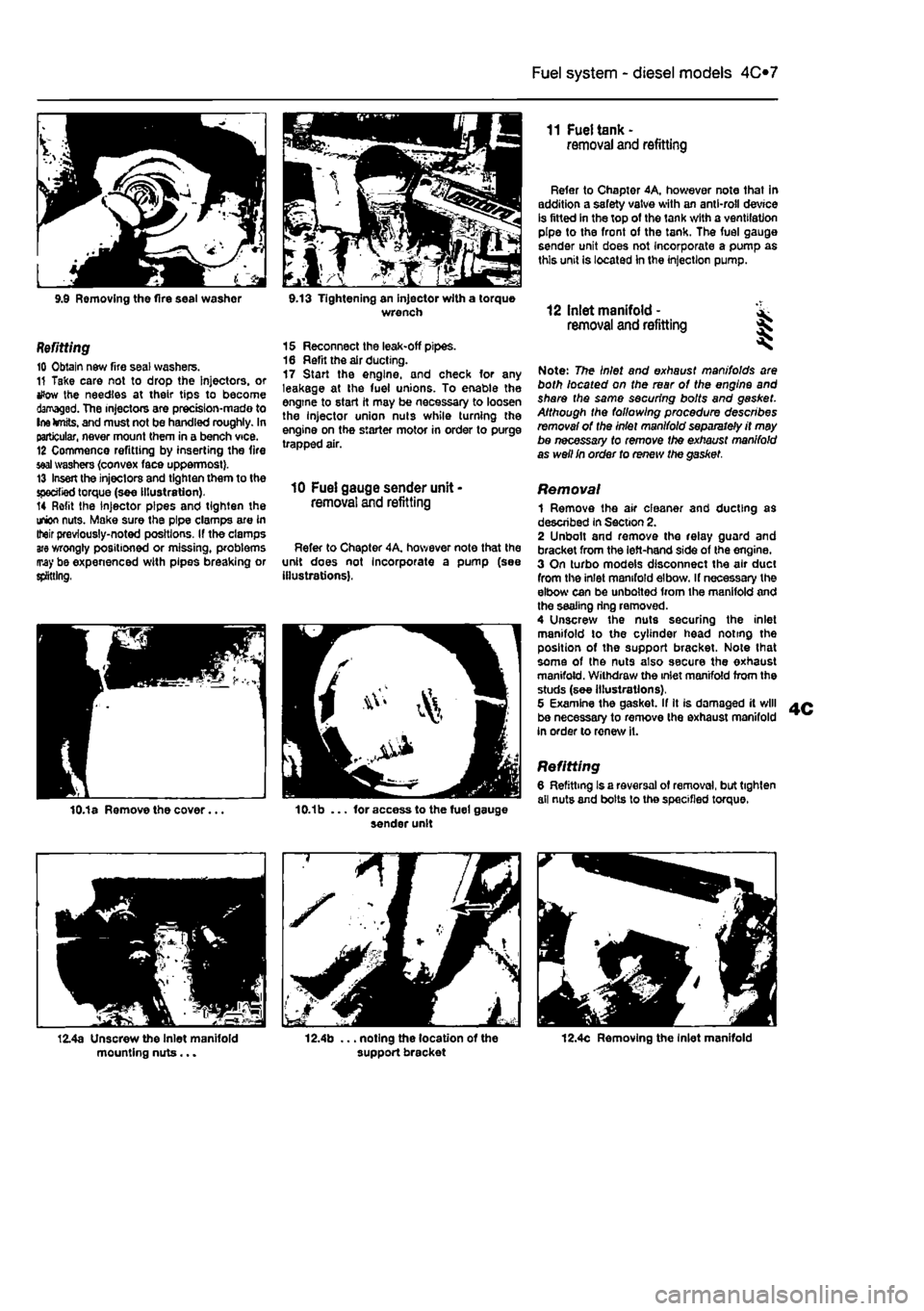
9.9 Removing the fire seal washor 9.13 Tightening an injector with a torque wrench
Refitting 10 Obtain new fire seal washers. 11 Take care not to drop the Injectors, or tfow the needles at their tips to become damaged. The injectors are prectsion-mado to Ine knits, and must not be handled roughly. In particular, never mount them in a bench vice. 12 Commence refitting by inserting the fire
seal
washers {convex face uppermost}. 13 Insert the injectors and tighten them to the specified torque (see illustration). 14 Refit the injector pipes and tighten the union nuts. Make sure the pipe clamps are in Iteir previously-noted positions. If the clamps
are
wrongly positioned or missing, problems may be expenenced with pipes breaking or splitting,
15 Reconnect the leak-off pipes. 16 Refit the air ducting. 17 Start the engine, and check for any leakage at the fuel unions. To enable the engine to start it may be necessary to loosen the Injector union nuts while turning the engine on the starter motor in order to purge trapped air.
10 Fuel gauge sender unit -removal and refitting
Refer to Chapter 4A, hov/ever note that the unit does not Incorporate a pump (see illustrations).
11 Fuel tank -removal and refitting
Refer to Chapter 4A, however note that in addition a safety valve with an anti-roll device is fitted in the top of the tank with a ventilation pipe to the front of the tank. The fuel gauge sender unit does not Incorporate a pump as this unit is located In the injection pump.
12 Inlet manifold - ^ removal and refitting %
Note: The Inlet and exhaust manifolds are both located on the rear of the engine and share the same securing bolts and gasket. Although the following procedure describes removal of the Inlet manifold separately it may be necessary to remove the exhaust manifold as well In order to renew the gasket.
Removal 1 Remove the air cleaner and ducting as described in Section 2. 2 Unbolt and remove the relay guard and bracket from the left-hand side of the engine. 3 On turbo models disconnect the air duct from the inlet manifold elbow. If necessary the elbow can be unbolted from the manifold and the sealing ring removed. 4 Unscrew the nuts securing the inlet manifold to the cylinder head noting the position of the support bracket. Note lhat some of the nuts also secure the exhaust manifold. Withdraw the inlet manifold from the studs (see illustrations), 5 Examine the gasket. If It is damaged it will be necessary to remove the exhaust manifold in order to renew it.
Refitting 6 Refitting Is a reversal of removal, but tighten all nuts and bolts lo the specified torque.
12.4c Removing the Inlet manifold
Page 212 of 225

Bodywork and fittings
11
*11
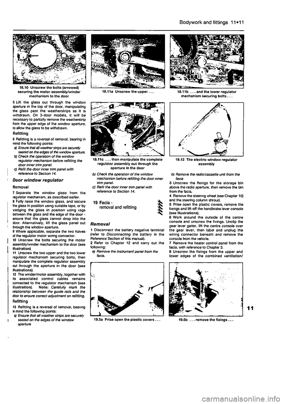
securing the motor assembly/winder mechanism to the door 5 Uft the glass out through the window aperture in the top of the door, manipulating the glass past the weatherstrips as it is withdrawn. On 3-door models, it will be necessary to partially remove the weatherstrip from the upper edge of Ihe window aperture, to allow the glass to be withdrawn. Refitting 6 Refitting is a reversal of removal, bearing in mind the following points: a) Ensure that all weather stnps are
securely
seated on the edges of the window aperture. b) Check the operation of the window regulator mechanism before refitting the door inner trim panel. | 0 Refit the door inner trim panel with | reference to Section 14.
1 Door window regulator
Removal 7 Separate the window glass from the regulator mechanism, as described earlier. 6 Fully raise the window glass, and secure the glass In position using suitable tape, or by wedging the glass in position using rags between the glass and the edge of the door • ensure that the glass cannot drop into the door. Alternatively, lift the glass panel out 1 through the window aperture. 9 Where applicable, separate the two halves of the regulator motor wiring connector. I 10 Unscrew the bolts securing the motor assembly/winder mechanism to the door (see Illustration). t1 Unscrew the two upper and the two lower regulator mechanism securing bolts, then manipulate the complete regulator assembly out through the aperture in the door (see illustrations). 12 The winder/motor assembly, together with its associated control cables remains connected to the regulator mechanism (see Illustration), Note: Carefully mark the relationship between the guide rails and the door to ensure correct adjustment on refitting. Refitting
13 Refitting is a reversal of removal, bearing r mind the following points: a) Ensure that all weather strips are securely I seated on the edges of the window aperture
16.11c ... then manipulate the complete regulator assembly out through the aperture in the door b) Check the operation of the window mechanism before refitting the door inner trim panel. c) Refil the door inner tnm panel with reference to Section 14.
19 Facia - ^ removal and refitting 5
Removal 1 Disconnect the batlery negative terminal (refer to Disconnecting the battery in the Reference Section of this manual). 2 Refer to Chapter 12 and carry out Ihe following: a) Remove the instrument panel from the facia.
19.5a Prise open the plastic covers...
18.11b ... and the lower regulator mechanism securing bolts...
assembly
b) Remove the radio/cassette unit from the facia 3 Unscrew the fixings for the storage bin above the radio aperture, then remove the bin from the facia. 4 Remove the steenng wheel (see Chapter 10) and the steering column shroud. 5 Prise open the plastic covers, remove the fixings and lift off the handbrake lever console (see Illustrations). 6 Work around the outside of the centre console and unscrew the fixings. Unclip the gear lever gaiter, lift the centre console over the gear lever, then label and unplug the wiring connector beneath and remove the console from the vehicle. 7 Remove the heater control panel from the facia, with reference to Chapter 3. 8 Unscrew the fixings from the upper and lower edges of the combined ventilation/
19.5b ... remove the fixings...
Page 213 of 225

11 *12 Bodywork and fittings
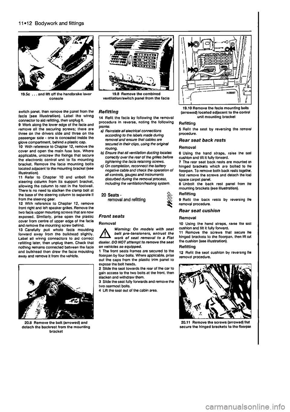
switch panel, then remove the panel from the facia (see illustration). Label tho wiring connector to aid refitting, then unplug It. 0 Work along the lower edge of Ihe facia and remove all the securing screws; there are three on the drivers side and three on the passenger side - one is concealed inside the glove compartment, behind a plastic cap. 10 Wilh reference to Chapter 12, remove the cover and open the main fuse box. Where applicable, unscrew the fixings that secure the electronic control unit to Its mounting bracket. Remove the facia mounting bolts located adjacent to the mounting bracket (see illustration). 11 Refer to Chapter 10 and unbolt the steering column from Its support bracket, allowing the column to rest in the footwell. There is no need to slacken the clamp bolt at Ihe base of the steering column to separate it from the steering gear. 12 With reference to Chapter 12, remove front right and left speaker grilles. Remove the two facis upper mounting screws ihat are now exposed. Similarly, prise open the plastic cover from centre of upper edge of the fada and remove the mounting screw behind. 13 Carefully pull whole facia moulding forward away from tho bulkhead slightly. Label all wiring connectors to aid correct refitting later, then unplug Ihem. Check that nothing remains connected between the facia and bulkhead then draw the facia moulding away and remove It from the vehicle.
20.8 Remove the bolt (arrowed) and detach the backrest from the mounting bracket
Refitting 14 Refit the facia by following the removal procedure in reverse, noting the following points: a) Reinstate all electrical connections according to (he labels made during removal and ensure that cables are secured in their clips, using the origins/ routing. b) Ensure thai all ventilation ducting locates correctly over the rear of the grilles before tightening the facia retaining screws. c) On completion, reconnect the battery negative cable and chock the operation of all controls, gauges and Instruments disturbed during the removal process, Including the ventilation/heating system.
20 Seats -removal and refitting JS:
Front seats
Removal
A
Warning: On models with seat belt pre-tonsionors, entrust the work of seat removal to a Flat dealer. DQNOTattempt to remove the seat on vehicles so equipped. 1 The front seats frames are secured to the fioorpan by four bolts. Whero applicable, prise out the caps from the plastic trim panel lo expose the bolt heads. 2 Slide the seat towards the rear of the car to gain access to the two bolts at the front, Ihen slacken and withdraw them. 3 Slide Ihe seat fully forwards and remove the two rearmost bolls. 4 Ufl the seat out of the cabin area.
(arrowed) located adjacent to the control unit mounting bracket Refitting 5 Refil the seat by reversing the remove! procedure. Rear seat back rests
Removal 6 Using the hand straps, raise the seal cushion and lilt it fully forward. 7 The rear seat back rests are mounted or hinged brackets which aro boiled to Ihe fioorpan. To remove both back rests together, first remove the screws and detach the load space carpet panel. 8 Unbolt the back rest panel from the mounting brackets (see illustration). Refitting 9 Refit tho back rests by reversing Ihe removal procedure. Rear seat cushion
Removal 10 Using the hand straps, raise the seat cushion and tilt it fully forward. 11 Remove ihe screws Ihat secure Ihe hinged brackets to tho fioorpan. then lift out the cushion (see illustration}. Refitting 12 Refit the seat cushion by reversing Ihe removal procedure.
20.11 Remove the screws (arrowed) that secure the hinged brackets to the fioorpan
Page 223 of 225

12*10 Body electrical systems
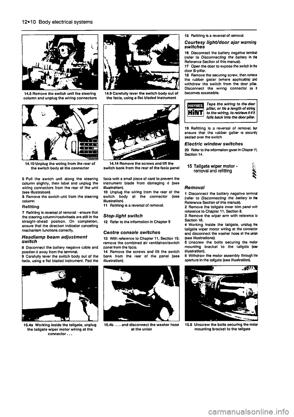
14.5 Remove the switch unit the steering column and unplug the wiring connectors 14.9 Carefully lever the switch body out of the facia, using a flat btaded instrument
14.10 Unplug the wiring from tho rear of the switch body at the connector
5 Pull the switch unit along ihe steering column slightly, then label and unplug the wiring connectors from the rear of the unit (sec Illustration). 6 Remove the switch unit from the steering column Refitting 7 Refitting is reversal of removal • ensure that the steering column/roadwheels are still in the straight-ahead position. On completion, ensure that the direction indicator cancelling mechanism lunations correctly.
Headlamp beam adjustment switch 8 Disconnect the battery negative cable and position il away from the terminal. 9 Carefully lever the switch body out of the facia, using a flat bladed instrument. Pad the
15 Refitting is a reversal of removal. Courtesy light/door ajar warning switches 16 Disconnect the battery negative terminal (refer to Disconnecting the battery in thf Reference Section of this manual). 17 Open the door to expose the switch
in
the door 8-plHar. 18 Remove the secunng screw, then remove the rubber gaiter (where applicable) ant) withdraw the switch from the door pillar. Disconnect the wiring connector as tl becomes accessible.
Tape the wiring to the
door
i m | pillar, or tie a length of
string
HlNTi to the wiring, to retrieve itttit falls back Into the door pillar.
14.14 Remove the screws and lift the switch bank from the rear of the facia panel
facia with a small piece of card to prevent the Instrument blade from damaging it (see illustration). 10 Unplug the wiring Irom Ihe rear of the switch body at Ihe connector (see illustration). 11 Refitting is a reversal of removal
Stop-light switch 12 Refer to the information in Chapter 9
Centre console switches 13 With reference to Chapter 11, Section 19, remove the combined air ventilation/switch panel from the facia. 14 Remove the screws and lift Ihe switch bank from Ihe rear of the panel (see illustration),
19 Refitting Is a reversal of removal, but ensure that the rubber gaiter is securely seated over the switch.
Electric window switches 20 Refer to the information given
In
Chapter It, Section 14.
15 Tailgate wiper motor - & removal and refitting ^
Removal 1 Disconnect the battery negative terminal (refer to Disconnecting the battery in the Reference Section of this manual), 2 Remove the tailgate inner trim panel with reference to Chapter 11, Section 8. 3 Remove the wiper arm with reference to Section 18. 4 Working inside the tailgate, unplug tlx tailgate wiper motor wiring at Ihe connector and disconnect the washer hose at
1he
union (see illustrations). 6 Unscrew the bolts securing the motor mounting bracket to the tailgate (see illustration). 6 Withdraw the motor assembly through tte aperture in the tailgate (see illustration).
15.4a Working inside the tellgate, unplug tho tailgate wiper motor wiring at the connector...
. and disconnect tho washer hose at the union 15.5 Unscrew the bolts securing the motor mounting bracket to the tailgate