Temperature sensor FIAT PUNTO 1999 176 / 1.G Owner's Manual
[x] Cancel search | Manufacturer: FIAT, Model Year: 1999, Model line: PUNTO, Model: FIAT PUNTO 1999 176 / 1.GPages: 225, PDF Size: 18.54 MB
Page 131 of 225
4A*2 Fuel system -
single-point
petrol Injection models
17 Have an assistant depress the accelerator pedal and check that the throttle cam opens luily and returns smoothly to its stop. If necessary, reposition the spring clip In the next outer cable groove and recheck the throttle operation. 18 Refit the remainder of the disturbed components.
5 Engine management
system
^ components
(1242
cc, 8-vatve § engines) -
removal and refitting
^
Note: Refer to the warning given In Section T
before
proceeding.
Throttle body assembly
Removal 1 Remove the air cleaner and inlet air duct as described in Section 2. 2 Disconnect the wiring connectors from the throttle potentiometer, the idle control stepper motor and the inlet air temperature sensor. 3 Slacken the accelerator cable locknuts, then disengage the inner cable from the throttle cam and free the outer cable from its retaining bracket. Position the cable clear of the throttle body. 4 Unclip and disconnect the EVAP purge valve hose, and Ihe MAP sensor hose from the rear of the throttle body then, where applicable, disconnect the fuel pressure regulator vacuum hose from the front of the throttle body. 5 Slacken and remove the four bolts securing the throttle body assembly to the inlet manifold, then remove the assembly along with its insulating spacer. Refitting 6 Refitting is a reversal of the removal pro-cedure. bearing in mind the following points: 4! Examine the Insulating spacer for signs of damage, and renew If necessary. b) Ensure the throttle body, inlet manifold and insulating spacer mating surfaces are clean and dry, then fit the throttle body and spacer, and securely tighten the retaining bolts. c) Ensure ail hoses are correctly reconnected and, where necessary, /her their retaining clips are securely tightened. d) Adjust the accelerator cable as described in Section 4.
Fuel
rail and injectors
Removal 7 Disconnect the battery negative terminal (refer to Disconnecting tho battery in the Reference Section of this manual). 6 Remove the throttle body assembly as described earlier in this Section, however it is only necessary to move the unit to one side for access to the fuel rail and therefore it Is unnecessary to disconnect the accelerator caWe and hoses etc.
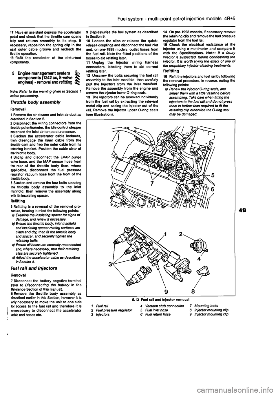
9 Depressurise Ihe fuel system as described in Section 9. 10 Loosen the clips or release the quick-release couplings and disconnect the fuel inlet and, on pre-1998 models, outlet hoses from the fuel rail. Note the fitted positions of the hoses to aid refitting later. 11 Unplug the ln}ector wiring harness connectors, labelling them to aid correct refitting later. 12 Unscrew the bolts securing the fuel rail assembly to the Inlet manifold, then carefully pull the Injectors from the Inlet manifold. Remove the assembly from the engine and remove the injector lower O-ring seals. 13 The injectors can be removed Individually from the fuel rail by extracting the relevant metal clip and easing Ihe injector out of the rail. Remove the injector upper O-ring seals (see illustration).
14 On pre-1998 models, if necessary remove the retaining clip and remove the fuel pressure regulator from the fuel rail. 15 Check the electrical resistance of the injector using a multimeter and compare It with the Specifications. Note: If a faulty Injector is suspected, before condemning the injector, It is worth trying the effect of one of the proprietary injector-cleaning treatments. Refitting 16 Refit the injectors and fuel rail by following the removal procedure, in reverse, noting the following points: a) Renew the injector O-rlng seals, and smear them with a little Vaseline before assembling. Take care when fitting the injectors to the fuel rail and do not press them in further than required to fit the retaining clip otherwise the O-ring seal may be damaged.
1 Fuel rail 2 Fuel pressure regulator 3 Injectors
5.13 Fuel rail and Injector removal 4 Vacuum stub connect/on 5 Fuel inlet hose 6 Fuel return hose
7 Mounting bolts 8 Injector mounting dip 9 Injector mounting dip
Page 132 of 225
4A*2 Fuel system -
single-point
petrol Injection models
b) Ensure that the injector retaining clips are securely seated c) Make sure the fuel supply and return hoses are correctly fitted as noted on removal, d) Check that all vacuum and electrical connections are remade
correcily
and securely. e) On completion check the fuel rail and injectors for fuel leaks.
Fuel pressure regulator Note: On J998 models onward, the fuel pressure regulator is an integral pad of the fuel pump and cannot be renewed separately. The following procedure applies to pre-1998 models only. Removal 17 Remove the air cleaner and inlet air ducts as described In Section 2. 18 Oepressurise the fuel system as described in Section 9. 19 Disconnect the vacuum hose from the port on the side of the regulator. 20 Extract the retaining clip and pull the pressure regulator out of Ihe fuel rail. 21 Remove the O-ring seal. Refitting 22 Refit the fuel pressure regulator by following Ihe removal procedure in reverse, noting the following points: a) Renew the O'ting seal and smear it with a little Vaseline before assembling. b) When fitting the retaining clip, use a suitable socket or metal tube (o press In the three anchorage points at Ihe same time. c) Refit the vacuum hose securely.
Idle control stepper motor
23 Refer to Chapter 4A.
Throttle potentiometer 24 Refer to Chapter 4A,
Intake air temperature sensor 25 Refer to Chapter 4A.
Manifold absolute pressure (MAP) sensor 26 Reler to Chapter 4A.
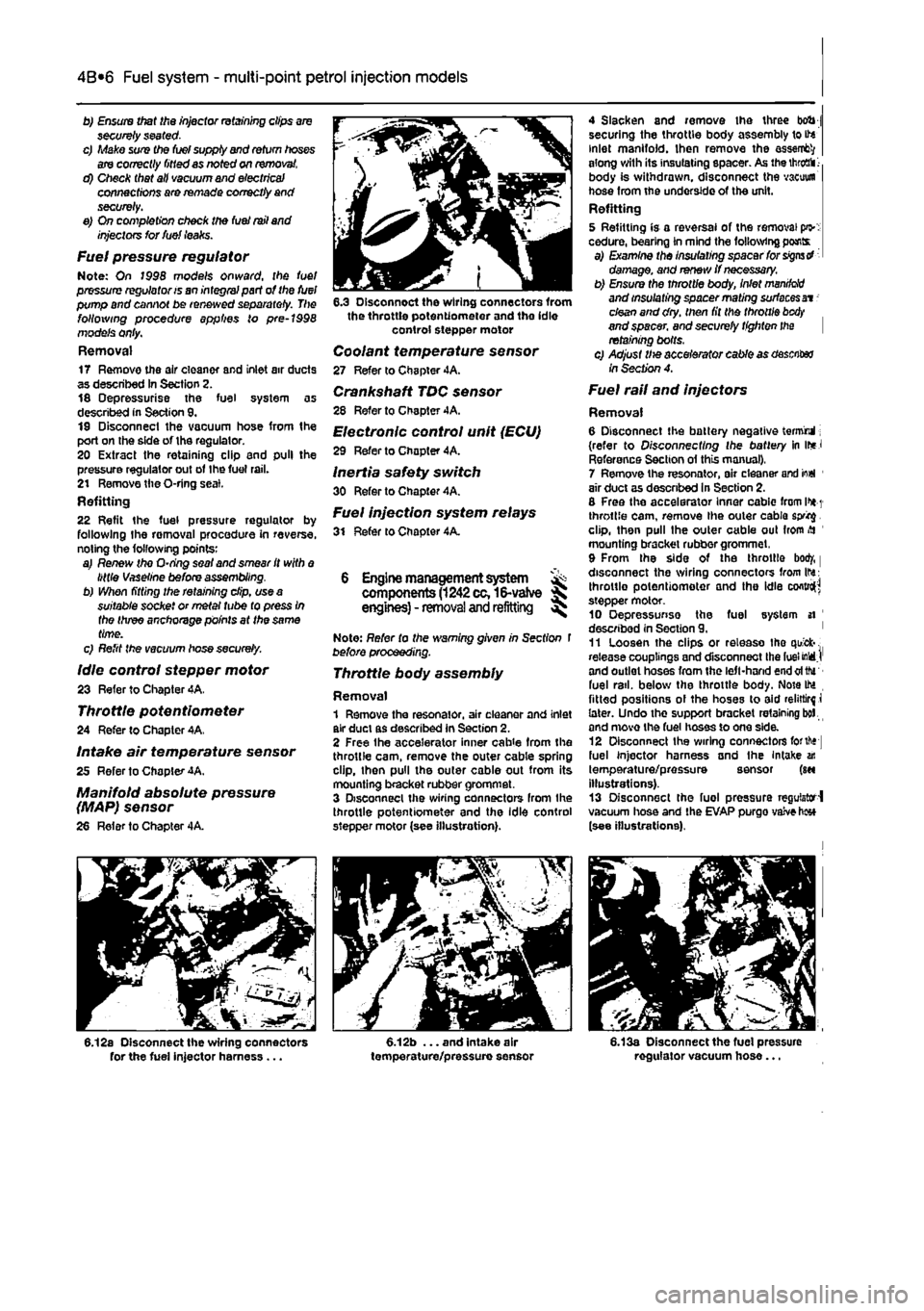
6.12a Disconnect the wiring connectors for the fuel injector harness ...
6.3 Disconnect the wiring connectors from the throttle potentiometer and the idle control stepper motor
Coolant temperature sensor 27 Refer to Chapter 4A. Crankshaft TDC sensor 28 Refer to Chapter 4A. Electronic control unit (ECU)
29 Refer to Chopter 4A.
Inertia safety switch 30 Refer to Chapter 4A. Fuel injection system relays 31 Refer to Chapter 4A.
6 Engine management system ^ components
(1242
cc,16-vatve S engines) - removal and refitting ^
Note: Refer to the warning given in Section t before proceeding.
Throttle body assembly
Removal 1 Remove the resonator, air cleaner and inlet air duct as described in Section 2. 2 Free Ihe accelerator inner cab
4 Slacken and remove the three bob j securing the throttle body assembly to ite inlet manifold. Ihen remove the assent?/ along with its insulating spacer. As the
throaii 1-
body is withdrawn, disconnect the vacuum hose from the underside of the unit. Refitting 5 Refitting is a reversal of the removal pi>: cedure, bearing in mind the following pants a) Examine the insulating spacer for signs d damage, and renew if necessary. b) Ensure the throttle body, inlet
manddd
and insulating spacer mating surfaces at -clean and dry. then fit the throttle
btxty
and spacer, and securely tighten the retaining bolts. c) Adjust Ute accelerator cable as desciter /nSecfw?4.
Fuel rail and injectors
Removal 6 Disconnect the battery negative termrul; (refer to Disconnecting the battery in ir*J Reference Section ol this manual), 7 Remove the resonator, air cleaner arid io«l 1 air duct as descnbed in Section 2. 8 Free the accelerator Inner cablc from l>*
1
throttle cam, remove the outer cable sprig. clip, then pull the outer cable out from
>H
mounting bracket rubber grommet, 9 From the side of the throttle bod/, | disconnect the wiring connectors from Ihs: throttle potentiometer and the idle cofttro^ stepper motor. 10 Oepressunse the fuel system si ' described in Section 9. ' 11 Loosen the clips or release tho quick-. release couplings and disconnect the fuel MdJ' and outlet hoses from the left-hand end oftfu fuel rail, below the throttle body. Note IM fitted positions ol the hoses to aid relirtirf i later. Undo the support bracket retaining bol and move the fuel hoses to one side. 12 Disconnect Ihe wiring connectors forth* fuel injector harness and the Intake an temperature/pressure sensor (m illustrations). 13 Disconnect the fuel pressure regulator-! vacuum hose and the EVAP purgo vaive h«* (see illustrations).
6.13a Disconnect the fuel pressure regulator vacuum hose...
Page 133 of 225
4A*2 Fuel system -
single-point
petrol Injection models
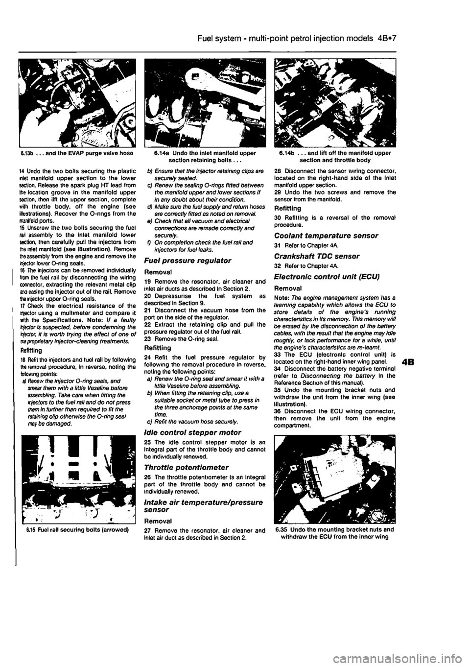
6.13b ... and tho EVAP purge valve hose
14 Undo the two bolls securing the plastic nlet manifold upper section to the lower section. Release the spark plug HT lead from Ihe location groove in the manifold upper section, then lift the upper section, complete with throttle body, off the engine (see illustrations). Recover the O-nngs from the manifold ports. 16 Unscrew the two bolts securing the fuel rail assembly to the Inlet manifold lower section, inen carefully pull the injectors from ttie inlet manifold (see Illustration). Remove
tt>e
assembly from the engine and remove the injector lower O-ring seals. t& The injectors can be removed individually from the fuel rail by disconnecting the wiring connector, extracting the relevant metal clip
ano
easing the injector out of the rail. Remove themjector upper O-ring seals. 17 Check the electrical resistance of the tractor using a multimeter and compare it with the Specifications. Note: If a faulty Rector fc suspected, before condemning Wie
Rector,
it is worth trying the effect of one of m
proprietary
injector-cleaning treatments. Refitting
15 Refit the injectors and fuel rail by following tie removal procedure, In reverse, noting the Mowing points:
4} Re/few
the Injector O-ring seals, and
smear
them with a little Vaseline before assembling. Take care when fitting the
injectors
to the fuel rail and do not press
them
in further than required to fit the
retaining
clip otherwise the O-ring
seal may
be damaged.
6.14a Undo the inlet manifold upper section retaining bolts ... b) Ensure that the injector retaining clips are securely seated. c) Renew the sealing O-nngs fitted between the manifold upper and lower sections if in any doubt about their condition. d) Make sure the fuel supply and return hoses are correctly fitted as noted on removal. e) Check that all vacuum and electrical connections are remade correctly and securely. f) On completion check the fuel rail and injectors tor fuel leaks.
Fuel pressure regulator
Removal 19 Remove the resonator, air cleaner and inlet air ducts as described In Section 2. 20 Depressurise the fuel system as described In Section 9. 21 Disconnect the vacuum hose from the port on the side of the regulator. 22 Extract the retaining clip and pull the pressure regulator out of the fuel rail. 23 Remove the O-ring seal. Refitting 24 Refit the fuel pressure regulator by following the removal procedure in reverse, noting the following points: a) Renew the O-ring
seaJ
and smear it with a little Vaseline before assembling. b) When fitting the retaining clip, use a suitable socket or metal tube to press in the three anchorage points at the same time. c) Refit the vacuum hose securely.
Idle control stepper motor 25 The idle control stepper motor is an Integral part of the throttle body and cannot be individually renewed.
Throttle potentiometer 26 The throttle potentiometer Is an integral part of the throttle body and cannot be individually renewed.
Intake air temperature/pressure sensor
Removal
6.14b ... and lift off the manifold upper section and throttle body 28 Disconnect the sensor wiring connector, located on the right-hand side of the Inlet manifold upper section. 29 Undo the two screws and remove the sensor from the manifold. Refitting 30 Refitting is a reversal of the removal procedure. Coolant temperature sensor 31 Refer to Chapter 4A.
Crankshaft TDC sensor 32 Refer to Chapter 4A.
Electronic control unit (ECU)
Removal Note: 77?e engine management system has a learning capability which allows the ECU to store details of the engine's running characteristics in Its memory. This memory will be erased by the disconnection of the battery cables, with the result that the engine may idle roughly, or lack performance for a while, until the engine's characteristics are re-learnt. 33 The ECU (electronic control unit) is located on the right-hand inner wing panel. 34 Disconnect the battery negative terminal (refer to Disconnecting the battery In the Reference Section of this manual). 35 Undo the mounting bracket nuts and withdraw the unit from the inner wing (see Illustration). 36 Disconnect the ECU wiring connector, then remove the unit from the engine compartment.
6.15 Fuel rail securing bolts (arrowed) 27 Remove the resonator, air cleaner and inlet air duct as described in Section 2. 6.35 Undo the mounting bracket nuts and withdraw the ECU from the inner wing
Page 134 of 225
4A*2 Fuel system -
single-point
petrol Injection models
Refitting 37 Refitting Is a reversal of removal making sure that the wiring connector is securely reconnected.
Inertia safety switch 36 Refer to Chapter 4A, Fuel injection system relays Removal 39 The fuel injection system twin relay Is located under a plastic cover on the engine compartment bulkhead. 40 The main purpose of the relay Is to supply current to the fuel pump, ignition coils, oxygen sensor, Injectors and EVAP solenoid. The relay is controlled by the ignition switch. A15 amp fuse, protecting ihe fuel pump, oxygen sensor and EVAP solenoid is located adjacent to the relay. 41 Remove the cover and pull the relay directfy from Its socket. Refitting 42 Refitting is a reversal of removal.
7 Fuel pump and fuel gauge sender unit - JK removal
and
refitting ^
Removal Note: Refer fo (he warning given in Section 1 before proceeding. 1 Disconnect the battery negative terminal (refer to Disconnecting the battery In the Reference Section of this manual). 2 Depreasurise the fuel system as described in Section 9. 3 Remove the rear soat as described In Chapter 11. Prise the fuel pump access cover out of the floor panel to gain access to the pump unit. On later models, undo the three retaining screws to release the cover. 4 Disconnect the wiring connector. 5 Bearing In mind the warning given In Section t, disconnect Ihe fuel supply and, where applicable, the return lines from tho pump unit by pressing the tabs. Plug the ends of the lines or cover them with adhesive tape. 6 Using a suitable tool, unscrew the large ring nut and carefully withdraw the fuel pump/fuel tank sender unit assembly from the fuel tank, along with its sealing rtng. 7 If necessary, the unit can be dismantled and the pump and sender unit separated. If this is (he case, carefully note the correct fitted positions of all components while dismantling the unit, and use these notes on reassembly to ensure that all items are correctly fitted.
Refitting 8 Refitting is a reversal of the removal procedure using a new sealing ring. Prior to refitting the access cover, reconnect the battery, then start the engine and check the fuel line unlon(s) (or signs of i
Fuel
tank -removal and refitting
Refer to Chapter 4A.
9 Fuel injection system -depressurisatton
Note: Refer to the warning given In Section 1 before proceeding.
A
Warning: The following procedure will merely relieve the pressure In the fuel system • remember that fuel will still be present In the system components and take precautions accord-ingly before disconnecting any of them. 1 The fuel system referred to in this Section is defined as the lank-mounted fuel pump, tha fuel filter, the fuel rail, the fuel injectors, and the metal pipes and flexible hoses of the fuel lines between these components. All these contain fuel which will be under pressure while the engine Is running and/or while the Ignition is switched on. The pressure will remain for some time after the Ignition has been switched off. and must be relieved before any of these components are disturbed for servicing work. 2 Disconnect the battery negative terminal (refer to Disconnecting the battery In the Reference Section of this manual). 3 Have a large rag ready to cover the union to be disconnected and, if possible, place a con-tainer beneath the relevant connection/union. 4 Slowly loosen the connection or union nut (as applicable) to avoid a sudden release of pressure, and ensure that the rag is wrapped around the connection to catch any fuef spray which may be expelled. Once the pressure is released, disconnect the fuel line, and Insert plugs to minimise fuel loss and prevent the entry of dirt Into the fuel system. Note that on later models, quick-release fuel couplings are used on many of the fuel line connections. To release these couplings, depress the two clips on the side of the coupling while keeping the fuel line pushed In. With the clips depressed, slowly withdraw the fuel line from the coupling allowing the fuel pressure to release, then withdraw the fuel line fully.
10 Inlet manifold-removal
and
refitting
Note: Refer fo the warning given in Section 1 before proceeding.
1242 cc (8-valve) engines
Removal 1 Remove ihe throttle body assembly as described in Section 5.
2 Remove the fuel rail and injectors at described in Section 5. 3 Drain the cooling system ss described n Chapter 1A. 4 Disconnect the wiring connector from ih* coolant temperature sensor (situated on it* left-hand side of the manifold). 5 Undo the bolt securing the accelerator cable mounting bracket to the manifold, am position it clear of the manifold. 6 Slacken the retaining clip and disconnect the coolant hose from the rear of the mandold 7 Disconnect the brake vacuum hose, 6 Undo the seven manifold retaining nuisw bolts, and remove the manifold from tta engine. Remove the gasket and discard tti new one should be used on refitting. Refitting
9 Refitting is a reverse of the removjf procedure, noting the following points: a) Ensure that the manifold and cylinder lim mating surfaces are dean and
dry.
and fill new manifold gasket. Refit the
manifold
and securely tighten Its retaining
nuts.
b) Ensure all relevant hoses are recorwscfed fo their original positions and are
sacurtfy
held (Where necessary; by the
retaining
clips. c) Refit the fuel rail and injectors, and
the
throttle body assembly with
reference to
Sect/on 5. d) On completion, refill the cooling
system
as described in Chapter 1A. 1242 cc (16-valve) engines
Removal 10 Disconnect the battery negative ternnncf (refer to Disconnecting the battery in ths Reference Section of this manual). 11 Remove the resonator, air cleaner and inlet air duct as described In Section 2. 12 Drain the cooling system as described r, Chapter 1A. 13 Free the accelerator inner cable from IN throttle cam. remove the outer cable spring dip. then pull the outer cable out from itt mounting bracket rubber grommet. 14 From the side of the throttle boOf, disconnect the wiring connectors from the throttle potentiometer and the Idle contrd stepper motor. Disconnect the coolant temperature sensor wiring connector located in the Inlet manilold below the throttie bodr, and disconnect the brake servo vacuum hose. 15 Disconnect Ihe wiring connectors for the fuel in|ector harness and the Intake a* temperature/pressure sensor, thtn disconnect the fuel pressure regulator vacuum hose and the EVAP purge valve
hose
(see illustration). 16 Undo Ihe two bolts securing the plastic Inlet manifold upper section to the lower section. Release the spark plug HT lead from the location groove in the manifold upper section, then lift Ihe upper section, complete with throttle body, off the engine. Recover
the
O-rings from the manifold pons.
Page 135 of 225
4A*2 Fuel system -
single-point
petrol Injection models
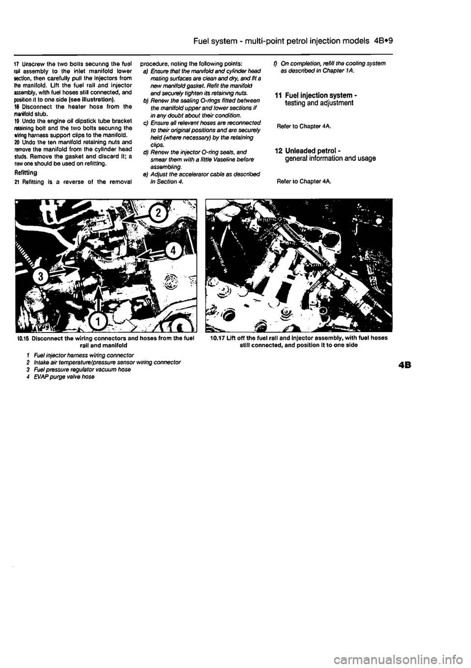
17 Unscrew the two bolts securing the fuel fell assembly to the Inlet manifold lower section, then carefully pull the injectors from Ihe manifold. Lift the fuel rail and injector assembly, with fuel hoses still connected, and position it to one side (see Illustration). 18 Disconnect the heater hose from the manifold stub. 19 Undo the engine oil dipstick tube bracket retaining bolt and the two bolts securing the *
one should be used on refitting. Refitting
21 Refitting is a reverse of the removal
procedure, noting the following points: a) Ensure that tha manifold and cylinder head mating surfaces are clean and dry. and fit
a
new manifold
gasf
f) On completion, refill the cooling system as described in Chapter 1A.
11 Fuel injection system testing and adjustment
Refer to Chapter 4A.
12 Unleaded petrol -general information and usage
Refer to Chapter 4A.
10.16 Disconnect the wiring connectors and hoses from the fuel rail and manifold 1 Fuel injector harness wiring connector 2 Intake air temperature/pressure sensor wiring connector 3 Fuel pressure regulator vacuum hose 4
EVAP
purge valve hose
10.17 Lift off the fuel rail and injector assembly, with fuel hoses still connected, and position it to one side
Page 144 of 225
4D«1
Chapter 4 Part D:
Exhaust and emission control systems
Contents
Catalytic converter - general Information and precautions 7 Crankcase emission system • general information 3 Evaporative loss emission control system • information and component renewal 2
Degrees of difficulty
Exhaust manifold - removal and refitting 5 Exhaust system - general information and component renewal .... 6 General information 1 Lambda oxygen sensor - removal and refitting 4
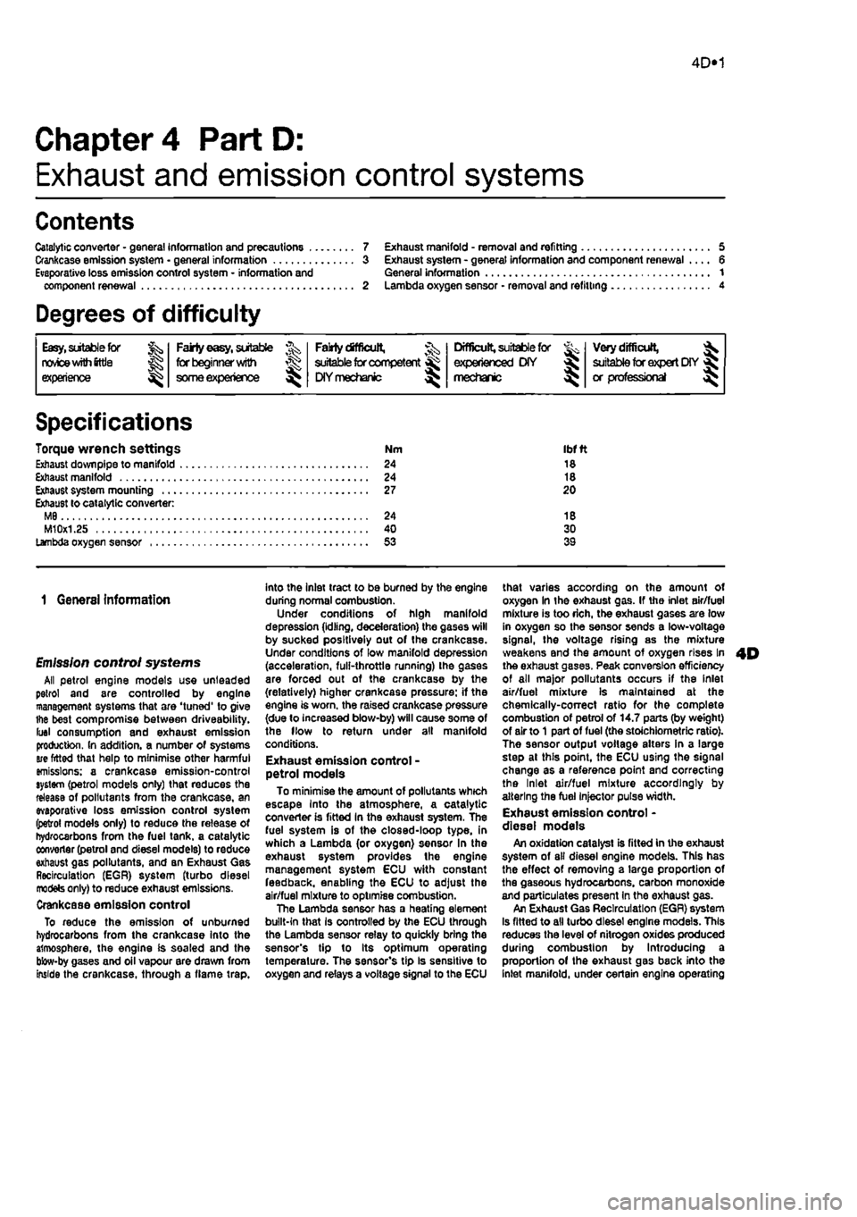
Easy, suitable
tor novice with fittie ^
1 experience
Fairly easy, suitable for beginner with ^ some experience ^
Fairiy dfficult, lb suitable for competent ^ DIY mechanic ^
Difficult, suitable for experienced DIY ^ mechanic
Very difficult, ^ suitable far expert DIY or professional
Specifications
Torque wrench settings Exhaust down pipe to manifold Exhaust manifold Exhaust system mounting Exhaust to catalytic converter: M8 M10x1.25
Nm Ibfft 24 18 24 18 27 20
24 18 40 30 53 39
1 General information
Emission control systems All petrol engine models use unleaded petrol and are controlled by engine management systems that are 'tuned' to give the best compromise between driveability. luel consumption and exhaust emission production. In addition, a number of systems are fitted that help to minimise other harmful emissions: a crankcase emission-control system (petrol models only) that reduces the release of pollutants from the crankcase, an evaporative loss emission control system (petrol models only) to reduce the release of hydrocarbons from the fuel tank, a catalytic converter (petrol and diesel models) to reduce exhaust gas pollutants, and an Exhaust Gas Recirculation (EGR) system (turbo diesel models only) to reduce exhaust emissions. Crankcase emission control To reduce the emission of unburned hydrocarbons from the crankcase Into the atmosphere, the engine is sealed and the blow-by gases and oil vapour are drawn from inside the crankcase, through a flame trap.
into the inlet tract to be burned by the engine during normal combustion. Under conditions of high manifold depression (idling, deceleration) the gases will by sucked positively out of the crankcase. Under conditions of low manifold depression (acceleration, full-throttle running) ihe gases are forced out of the crankcase by the (relatively) higher crankcase pressure: if the engine is worn, the raised crankcase pressure (due to increased blow-by) will cause some of the flow to return under all manifold conditions. Exhaust emission control -petrol models To minimise the amount of pollutants which escape Into the atmosphere, a catalytic converter is fitted In the exhaust system. The fuel system is of the closed-loop type, in which a Lambda (or oxygen) sensor In the exhaust system provides the engine management system ECU with constant feedback, enabling the ECU to adjust the air/fuel mixture to optimise combustion. The Lambda sensor has a heating element built-in that Is controlled by the ECU through the Lambda sensor relay to quickly bring the sensor's tip to Its optimum operating temperature. The sensor's tip Is sensitive to oxygen and relays a voltage signal to the ECU
that varies according on the amount of oxygen In the exhaust gas. If the inlet air/fuel mixture is too rich, the exhaust gases are low in oxygen so the sensor sends a low-voltage signal, the voltage rising as the mixture weakens and the amount of oxygen rises In the exhaust gases. Peak conversion efficiency of all major pollutants occurs if the inlet air/fuel mixture Is maintained at the chemlcally-con*ect ratio for the complete combustion of petrol of 14.7 parts (by weight) of air to
1
part of fuel (the stoichiometric ratio). The sensor output voltage alters in a large step at this point, the ECU using the signal change as a reference point and correcting the Inlet air/fuel mixture accordingly by altering the fuel Injector pulse width. Exhaust emission control -diesel models An oxidation catalyst is fitted in the exhaust system of all diesel engine models. This has the effect of removing a large proportion of the gaseous hydrocarbons, carbon monoxide and particulates present in the exhaust gas. An Exhaust Gas Recirculation (EGR) system Is fitted to all turbo diesel engine models. This reduces the level of nitrogen oxides produced during combustion by Introducing a proportion of the exhaust gas back into the inlet manifold, under certain engine operating
Page 168 of 225
Automatic transmission 7B*3
11 When reverse gear Is selected, the control unit keeps the transmission In tow ratio, if this were not the case, it would, In theory, be possible to drive as fast In reverse as in forward gear. 12 An electronic control unit supplies the current to energise the clutch. The control unit receives signals concerning engine speed, road speed, accelerator pedal position, and gear selector position, Sensors include the following. a) Engine rpm sensor (from the Injection/ignition control unit) b) Accelerator pedal switch
c) Throttle valve position sensor d) Selector lever position sensor e) Vehicle speed sensor f) Coolant temperature sensor g) Air conditioning sensor h) Brake switch I) Torque signal
13 The final drive/differential unit Is conventional. Drive from the driven pulley is transmitted to the differential by an Intermediate reduction gear. 14 The ECVT incorporates a warning light which illuminates when a fault occurs.
Precautions 1$ Observe the following precautions to avoid damage to the automatic transmission: a) Do not attempt to start the engine by pushing or towing the car. b) If the car has to be towed for recovery, the distance must not exceed 12 miles (20
km),
and the speed must not exceed
19
mph
(30 kph).
If these conditions cannot be met, or If transmission damage is suspected, only tow the car with the front wheels clear of the ground. c) Only engage P or R when the vehicle is stationary.
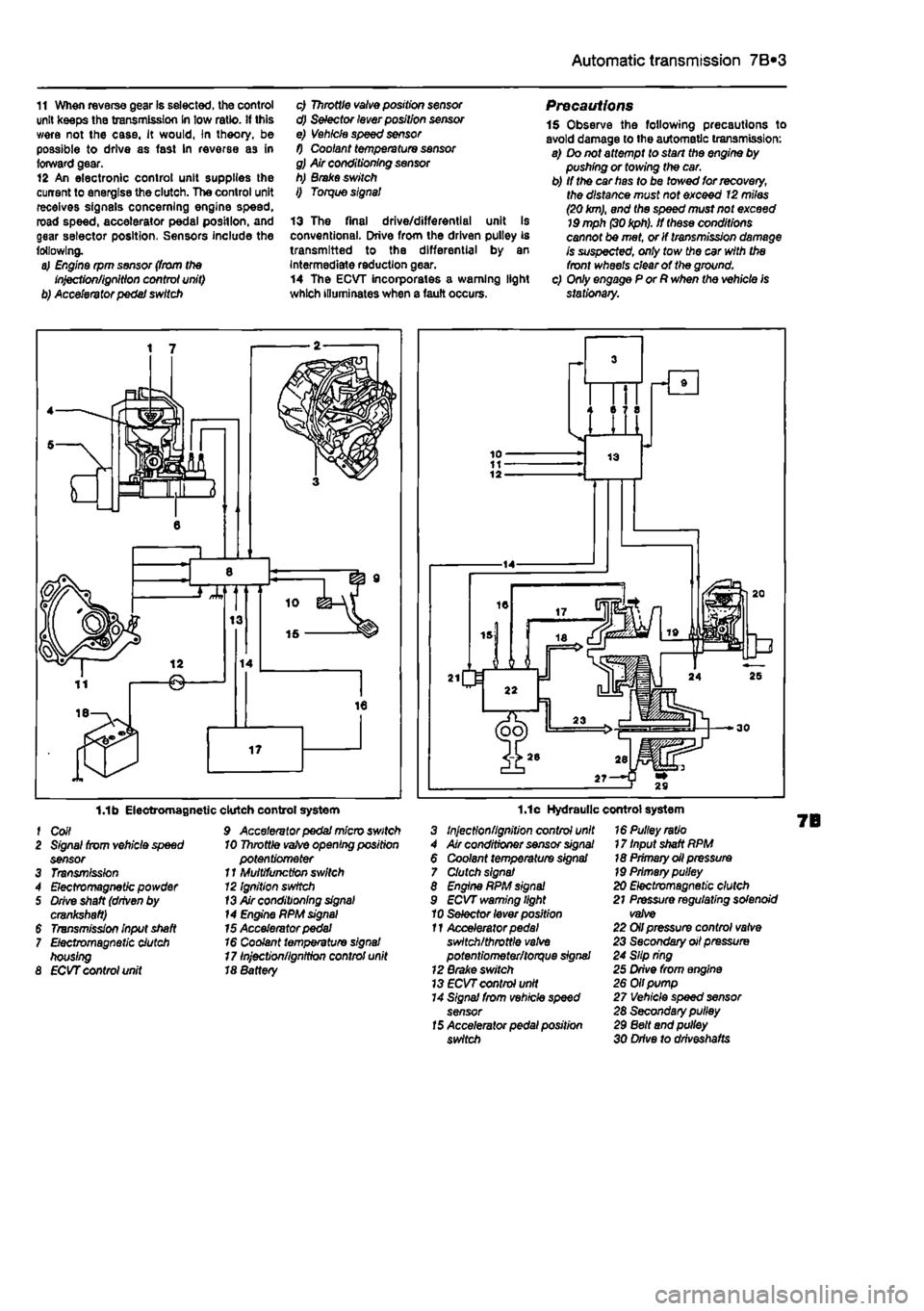
1.1b Electromagnetic f Coil 2 Signal from vehicle speed sensor 3 Transmission 4 Electromagnetic powder 5 Drive shaft (driven by crankshaft) $ Transmission input shaft 7 Electromagnetic clutch housing 8 ECVT control unit
clutch control system 9 Accelerator pedal micro switch 10 Throttle
vafve
opening position potentiometer 11 Multifunction switch 12 Ignition switch
13
Air conditioning
signal
14 Engine PPM
signal
15 Accelerator pedal 16 Coolant temperature signal 17 Injection/ignition control unit 18 8attery
1.1c Hydraulic control system 3 Injection/ignition control unit 4 Air conditioner sensor
signal
6 Coolant temperature signal 7 Clutch signal 8 Engine RPM
signal
9 ECVT warning light 10 Selector lever position 11 Accelerator
pedal
switch/throttle
valve
potentiometer/torque signal 12 Brake switch 13
ECVT
control unit 14 Signal from vehicle speed sensor
15
Accelerator pedal position switch
16 Pulley ratio 17 Input shaft RPM 18 Primary oil pressure
19
Primary pulley 20 Electromagnetic clutch 21 Pressure regulating solenoid valve 22 Oil pressure control valve 23 Secondary oil pressure 24 Slip ring 25 Drive from engine 26 Oil pump 27 Vehicle speed sensor 28 Secondary pulley 29 Belt and pulley 30 Drive to drlveshafts