turbo FIAT PUNTO 1999 176 / 1.G Owner's Manual
[x] Cancel search | Manufacturer: FIAT, Model Year: 1999, Model line: PUNTO, Model: FIAT PUNTO 1999 176 / 1.GPages: 225, PDF Size: 18.54 MB
Page 145 of 225
4D*2 Exhaust and emission control systems
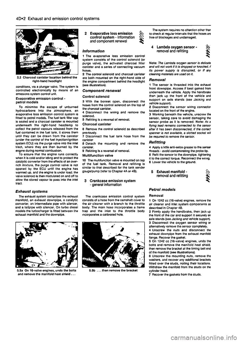
2.2 Charcoal canister location behind tho right-hand headlight
conditions, via a plunger valve, The system is controlled electronically by means of an emissions system control unit. Evaporative emission control • petrol models To minimise the escape of unburned hydrocarbons Into the atmosphere, an evaporallve loss emission control system is fitted to petrol models, The fuel tank filler cap Is sealed and a charcoal canister is mounted underneath the right-hand headlamp to collect the petrol vapours released from the fuel contained In the fuel tank. It stores them until they can be drawn from the canister (under the control of the fuel Injection/ignition system ECU) via the purge valve into the Inlet tract, where they are then burned by the engine during normal combustion. To ensure thai the engine runs correctly when it is cold and/or idling and to protect the catalytic converter from the effects of an over-rich mixture, the purge control valve is not opened by the ECU until the engine has warmed up, and the engine is under load; the valve solenoid is then modulated on and off to allow the stored vapour to pass into the inlet tract.
Exhaust systems The exhaust system comprises the exhaust manifold, an exhaust downpipe, • catalytic convorter, an intermediate pipe with silencer, and a tailpipe with silencer, On turbo diesel models the turbocharger is fitted between ihe exhaust manifold and the downpipe.
5.5a On 16-valve engines, undo the bolts and remove the manifold heat shield...
2 Evaporative loss emission ^ control system - information and component renewal ^
Information 1 The evaporative loss omission control system consists of the control solenoid (or purge valve), the activated charcoal filter canister and a series of connecting vacuum hoses. 2 The control solenoid and charcoal canister are both mounted on the right-hand side of the engine compartment behind the headlight (see illustration).
Component renewal
Control solenoid 3 With the bonnet open, disconnect the hoses from the control solenoid on the top of the charcoal canister. 4 Disconnect the wiring and remove the solenoid. 5 Refitting is a reversal of removal. Charcoal canister 6 Remove Ihe control solenoid as desenbed previously. 7 Disconnect Ihe fuel tonk hose from the canister 8 Detach the mounting and remove the canister. 9 Refitting Is a reversal of removal. Multifunction valve 10 The multifunction valve >s mounted on top of the luel tank. Removal and refitting is similar to that described for the tank sender gauge/pump (refer to Chapter 4A or 4B).
3 Crankcase emission system - general information
The crankcase emission control system consists of a hose from the camshaft cover to the air cloanor with a branch to Ihe throttle body. The main hose Incorporates a flame trap and the Inlet to the throttle body incorporates a calibrated hole.
5.5b ... then remove the bracket
The system requires no attention other than to check at regular intervals that tho hoses are free of blockages and undamaged.
4 Lambda oxygen sensor -removal and refitting &
Note: 7?5e Lambda oxygen sensor is doiicata and will not work if it is dropped or knocked, it its power supply is disrupted, or if any cleaning materials are used on it.
Removal 1 The sensor Is threaded Into the exhaust front downpipe. Access if best gained Irom underneath the vehicle. Apply the handbrake then )ack up the front of the vehicle and support on axle stands (see Jacking and vehicle support). 2 Disconnect the sensor wiring connector located on the front of the engine. 3 Working beneath the vehicle, unscrew the sensor, taking care to avoid damaging the sensor probe as it Is removed- Note: As a flying lead remains connected to the sensor after it has been disconnected, if the correct spanner is not available, a slotted socket
will
be required to remove the sensor.
Refitting A Apply a little anti-selze grease to (he sensor threads • avoid contaminating the probe tip. 5 Refit the sensor to the downpipe. tightening it to the correct torque. Reconnect the wiring. 6 Lower the vohicle to the ground.
5 Exhaust manifold - % removal and refitting jk
Petrol models
Removal 1 On 1242 cc (16-valve) engines, remove tho air cleaner and inlet system components as described in Chapter 48. 2 Firmly apply the handbrake, then jock up the front of the car and support It securely on axle stands (see Jacking and vehicle support). 3 Disconnect the oxygen sensor wiring or alternatively romovo Ihe sensor completely. 4 Unscrew the nuts and disconnect the exhaust downpipo from Ihe exhaust manifold flange. Recover the gasket. 5 On 1242 cc (16-valve) engines, undo the bolts and remove the manifold heat shield, then remove the bracket at the timing belt end of the manifold (seo Illustrations). 6 Unscrew the mounting nuts, remove the washers, and recover any additional brackets fitted over the studs, noting their locations. Withdraw the manifold from the studs on the cylinder head. 7 Recover the gaskets from Ihe studs.
Page 146 of 225
4D*3 Exhaust and emission control systems
Refitting 8 Refitting is a reversal of the removal pro-cedure but fit new gaskets. Tighten the nuts lo the specified torque.
Diesel models Note: On diesel models the inlet and exhaust
manifolds
are located on the rear of the engine
end
share the same securing nuts and gasket. Removal 8 Remove the inlet manifold as described In Part
C
of this Chapter. 10 Firmly apply the handbrake, then jack up lite front of tho car and support it securely on axle stands (see Jacking and vehicle support). 11 Straighten the tab washers (where fitted), then unscrew and remove the exhaust downpipe retaining nuts. Detach the downpipe from the manifold/turbocharger. Suitably support the downpipe. 12 Undo the manifold-to-cylinder head securing nuts and withdraw the manifold (see Illustration). 13 Separate the turbocharger from the manifold with reference to Chapter 4C. 14 Remove the gasket and clean the mating
(aces
of the manifold, cylinder head and down-pipe flange (see illustration). The gasket must
be
renewed when refitting the manifold, Refitting
15 Refitting is a reversal of the removal procedure but fit a new gasket. Tighten the retaining nuts to the specified torque and where necessary lock them by bending over
the
tocktabs.
6 Exhaust system - % general information and ^ component renewal
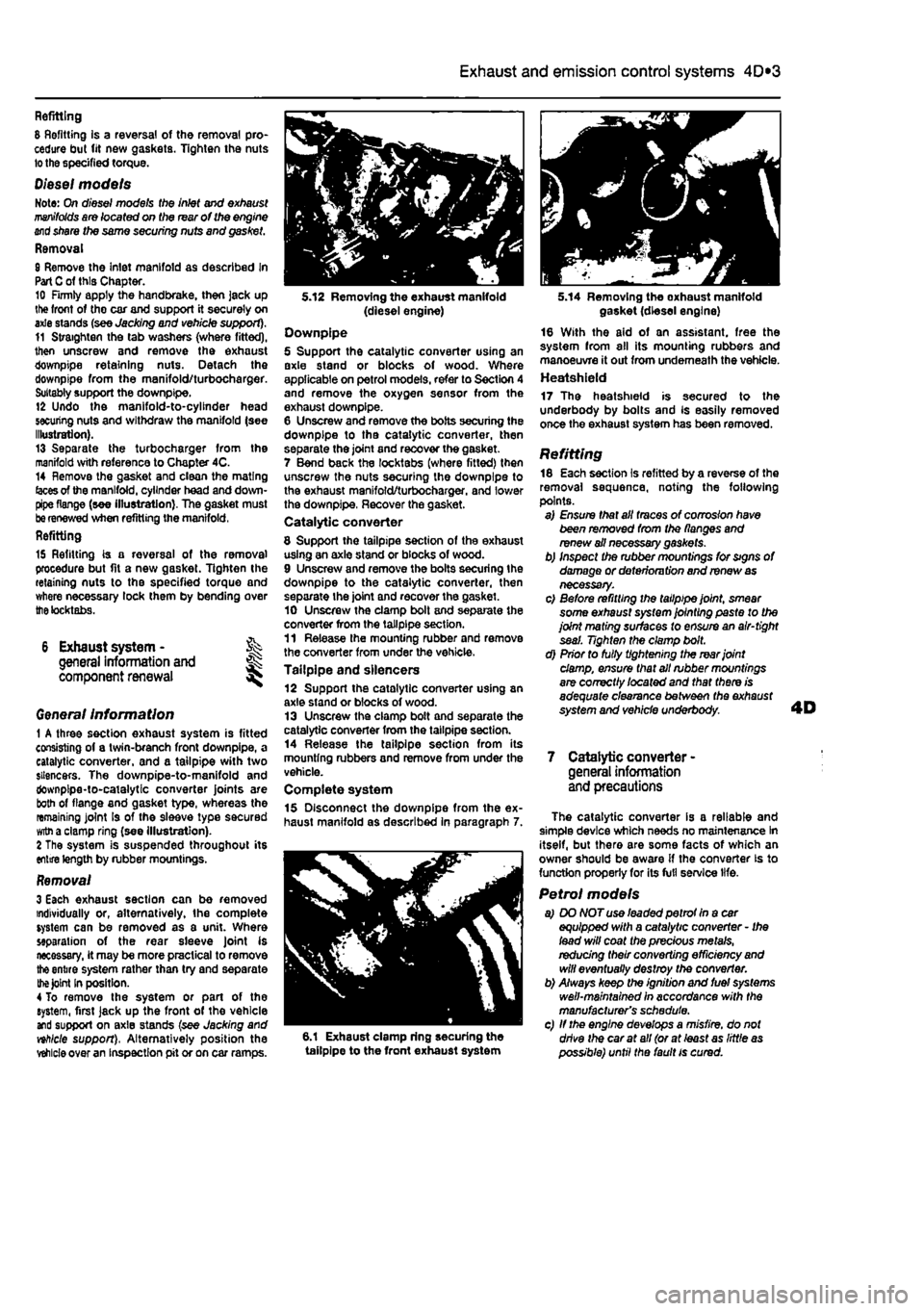
Genera/ Information 1 A three section exhaust system is fitted consisting of a twin-branch front downpipe, a catalytic converter, and a tailpipe with two silencers. The downpipe-to-manifold and downpipe-to-catalytic converter joints are both of flange and gasket type, whereas the remaining joint Is of the sleeve type secured
witn
a clamp ring (see illustration). 2 The system is suspended throughout its entire length by rubber mountings.
Removal 3 Each exhaust section can be removed individually or, alternatively, the complete system can be removed as a unit. Where separation of the rear sleeve Joint is necessary, it may be more practical to remove
the
entire system rather than try and separate
the Joint
In position. 4 To remove the system or part of the system, first jack up the front of the vehicle and support on axle stands (see Jacking and nhlcle support), Alternatively position the
vehicle
over an inspection pit or on car ramps.
5.12 Removing the exhaust manifold (diesel engine) Downpipe 5 Support the catalytic converter using an axle stand or blocks of wood. Where applicable on petrol models, refer to Section 4 and remove the oxygen sensor from the exhaust downpipe. 6 Unscrew and remove the bolts securing the downpipe to tha catalytic converter, then separate the joint and recover the gasket. 7 Bend back the locktabs (where fitted) then unscrew the nuts securing the downpipe to the exhaust manifold/turbocharger. and lower the downpipe, Recover the gasket. Catalytic converter
8 Support the tailpipe section of the exhaust using an axle stand or blocks of wood. 9 Unscrew and remove the bolts securing the downpipe to the catalytic converter, then separate the joint and recover the gasket. 10 Unscrew the clamp bolt and separate the converter from the tailpipe section. 11 Release the mounting rubber and remove the converter from under the vehicle. Tailpipe and silencers 12 Support the catalytic converter using an axle stand or blocks of wood. 13 Unscrew the clamp bolt and separate the catalytic converter from the tailpipe section. 14 Release the tailpipe section from its mounting rubbers and remove from under the vehicle. Complete system 15 Disconnect the downpipe from the ex-haust manifold as described in paragraph 7.
6.1 Exhaust clamp ring securing the tailpipe to the front exhaust system
5.14 Removing the oxhaust manifold gasket (diesel engine) 16 With the aid of an assistant, free the system from all its mounting rubbers and manoeuvre it out from underneath the vehicle. Heatshield 17 The heatshield is secured to the underbody by bolts and Is easily removed once the exhaust system has been removed.
Refitting 18 Each section is refitted by a reverse of the removal sequence, noting the following points. a) Ensure that all traces of corrosion have been removed from the flanges and renew ail necessary gaskets. b) Inspect the rubber mountings for signs of damage or deterioru tion and renew
as
necessary. c) Before refitting the tailpipe joint, smear some exhaust system jointing paste to the joint mating surfaces to ensure an air-tight seal. Tighten the clamp bolt. d) Prior to fully tightening the rear joint damp, ensure that all rubber mountings are correctly /ocafed and that there is adequate clearance between the exhaust system and vehicle underbody.
7 Catalytic converter -general information and precautions
The catalytic converter is a reliable and simple device which needs no maintenance In itself, but there are some facts of which an owner should be aware if the converter is to function properly for its full service life.
Petrol models a) DO NOT use leaded petrot In a car equipped with a catalytic converter - Ihe lead will coat the precious metals, redudng their converting efficiency
and
will eventually destroy the converter. b) Always keep the ignition and fuel systems well-maintained in accordance with the manufacturer's schedule. c) If the engine develops a misfire, do not drive the car at all (or at least as little
as
possible) until the fault is cured.
Page 162 of 225
7A»1
Chapter 7 Part A:
Manual transmission
Contents
Gearchange lever and linkage - removal and refitting 2 General information 1 Manual transmission oil level check See Chapter 1A or 18 Manual transmission oil renewal See Chapter 1A or 1B
Manual transmission overhaul • general information 4 Manual transmission • removal and refitting 3 Reversing light switch • testing, removal and refitting 5
Degrees of difficulty
Easy, suitable
for Faiity
easy,
suitable FaMycffficult, ^ Difficult,
sutable fa-
Verycfifficutt, ^
novice with
little
1
for beginner with suitable
for
competent experienced DIY * * < siitable
for
expert
DIY
jR or professional ^ experience 1
some
experience DIYmechanic ^ mechanic * * < siitable
for
expert
DIY
jR or professional ^
Specifications
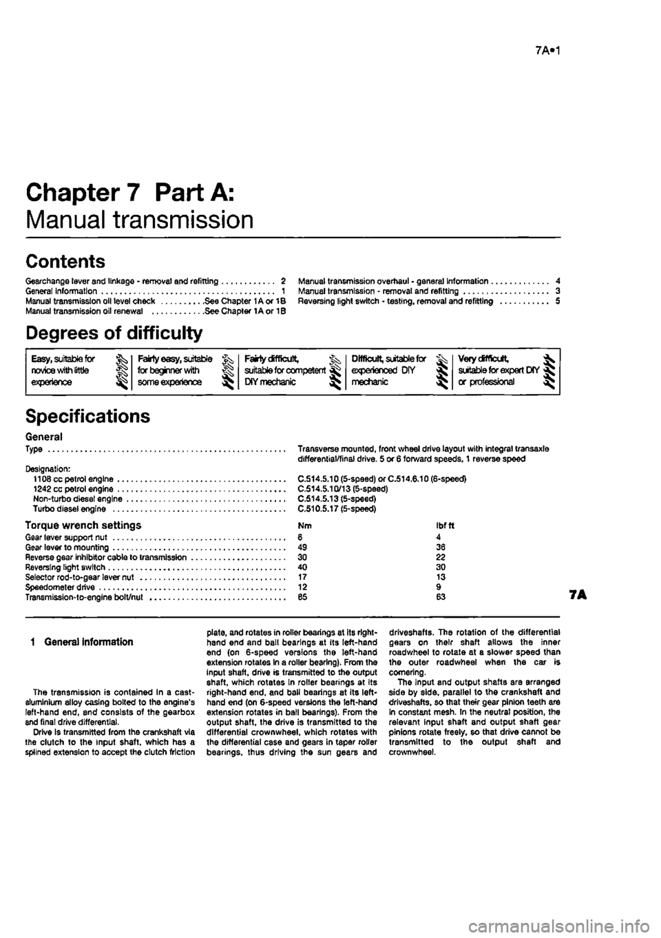
General Type
Designation: 1108 cc petrol engine 1242 cc petrol engine Non-turbo diesel engine Turbo diesel engine
Torque wrench settings Gear lever support nut Gear lever to mounting Reverse gear inhibitor cable to transmission Reversing light switch Selector rod-to-gear lever nut Speedometer drive Transmission-to-engine bolt/nut
Transverse mounted, front wheel drive layout with integral transaxle differential/final drive. 5 or 6 forward speeds, 1 reverse speed
C.S14.5.10 (5-speed) or C.514.6.10 (6-speed) C.514.5.1Q/13 (5-speed) C.514.5.13 (5-speed) C.510.5.17 (5-speed)
Nm Ibftl 6 4 49 36 30 22 40 30 17 13 12 9 es 63
1 Genera) Information
The transmission is contained In a cast-aluminium alloy casing bolted to the engine's left-hand end, and consists of the gearbox end final drive differential, Drive Is transmitted from the crankshaft via the clutch to the Input shaft, which has a spiined extension to accept the clutch friction
plate, and rotates in roller bearings at its right-hand end and ball bearings at its left-hand end (on 6-speed versions the left-hand extension rotates In a roller bearing). From the input shaft, drive is transmitted to tho output shaft, which rotates In roller bearings at Its right-hand end. and ball bearings at its left* hand end (on 6-speed versions the left-hand extension rotates in ball bearings). From the output shaft, the drive is transmitted to the differential crownwheel, which rotates with the differential case and gears in taper roller bearings, thus driving the sun gears and
driveshafts. The rotation of the differential gears on their shaft allows the inner roadwheel to rotate at a slower speed than the outer roadwheel when the car is cornering. The Input and output shaftB are arranged side by side, parallel to the crankshaft and driveshafts, so that their gear pinion teeth are In constant mesh. In the neutral position, the relevant input shaft and output shaft gear pinions rotate freely, so that drive cannot be transmitted to the output shaft and crownwheel.
Page 172 of 225
6*172
Chapter 8
Driveshafts
Contents
Oriveshaft gaiter check See Chapter 1A or 1B General information 1 Oriveshaft overhaul and rubber gaiter renewal 3 intermediate driveshaft - removal and refitting 4 Driveshafts - removal and refitting 2
Degrees of difficulty
Easy,
suitable for ^ novtoewithittle experience ^
Fatly
easy,
suitable for beginner with
some experience
^
Fairty
difficult, suitable
tor
competent OtYmechanlc
Difficult,
suitable for experienced DIY mechanic ^
Veiydfficult, ^
suitable
for
expert DIY
or professional ^
Specifications
General Type
Lubrication lubricant type
Torque wrench settings Driveshaft nut* All models except turbo diesel (M22 plain) Turbo diesel (M24 with staking and captive washer) Roadwheel bolts Suspension strut-to-hub carrier bolts Track-rod balljolnt-to-hub carrier 'Use a new nut.
Unequal-length, solid steel shafts, splined to Inner and outer constant velocity joints. Intermediate shaft with support bearing on turbo diesel models with equal length driveshafts.
Fiat specification grease, supplied with gaiter repair kit
Nm Ibfft
240 177 280 207 85 63 70 52 40 30
1 General information
Power is transmitted from the differential to
Ihe
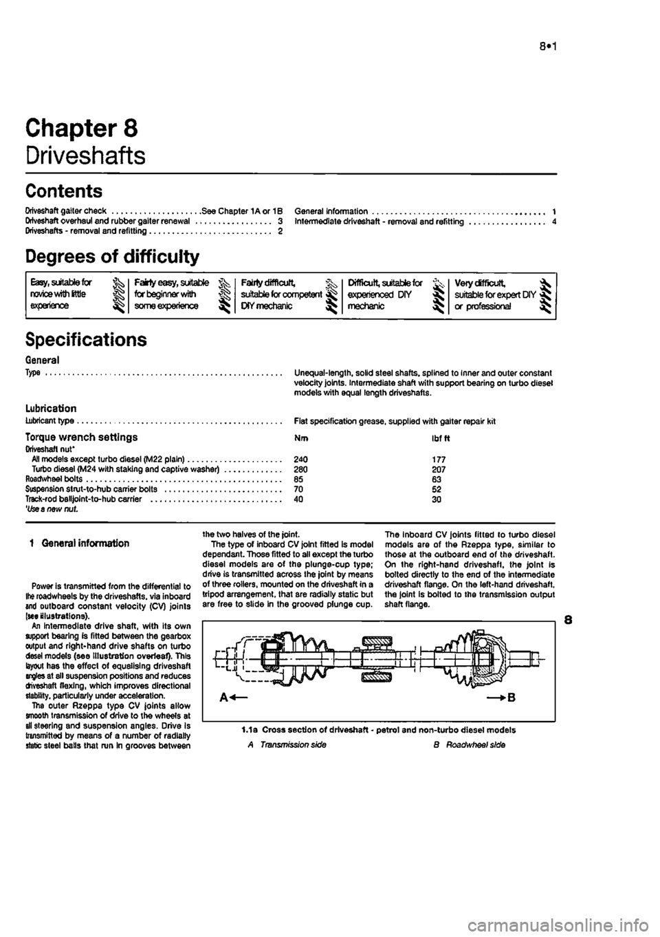
roadwheels by the driveshafts. via inboard and outboard constant velocity (CV) joints (we illustrations). An intermediate drive shaft, with its own support bearing is fitted between the gearbox output and right-hand drive shafts on turbo desei models (see Illustration overleaf). This layout has the effect of equalising driveshaft angles at sll suspension positions and reduces tfveshaft flexing, which improves directional stability, particularly under acceleration. The outer Rzeppa type CV joints allow smooth transmission of drive to the wheels at all steering and suspension angles. Drive Is transmitted by means of a number of radially static steel balls that run In grooves between
the two halves of the joint. The type of inboard CV joint fitted is model dependant. Those fitted to all except the turbo diesel models are of the plunge-cup type; drive is transmitted across the joint by means of three rollers, mounted on the driveshaft in a tripod arrangement, that are radially static but are free to slide in the grooved plunge cup.
The inboard CV joints fitted to turbo diesel models are of the Rzeppa type, similar to those at the outboard end of the driveshaft. On the right-hand driveshafl, the joint is bolted directly to the end of the intermediate driveshaft flange. On the left-hand driveshaft, the joint is bolted to the transmission output shaft flange.
1.1a Cross section of driveshaft - petrol and non-turbo diesel models A Transmission side B Roadwheef side
Page 173 of 225
8*2 Driveshafts
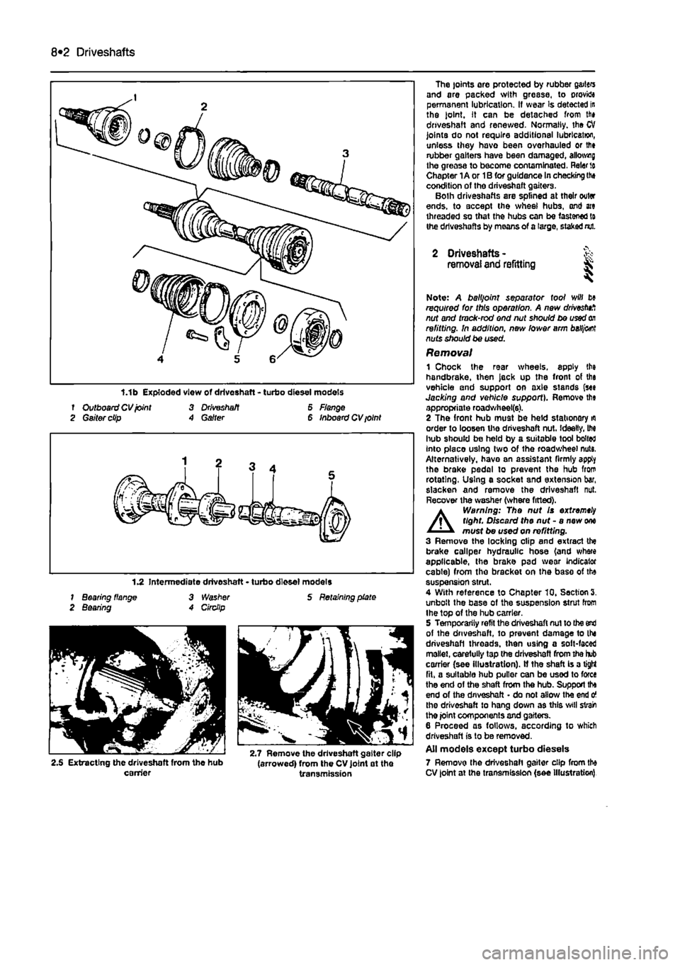
f Outboard CV joint 3 Driveshaft 6 Flange 2 Gaiter clip A Garter 6 Inboard CV ioint
1.2 Intermediate driveshaft • turbo diesel models 1 Bearing flange 3 Washer S Retaining plate 2 Bearing A Circllp
2.S Extracting the driveshaft from the hub (arrowed) from the CV joint at the carrier transmission
The joints are protected by rubber g&itcrs and are packed with grease, to orovktt permanent lubrication. If wear Is detected in the joint. It can be detached from lii» driveshaft and renewed. Normally, the CV joints do not require additional lubrication, unless they havo been overhauled or lfi» rubber gaiters have been damaged, allotting the greasa to become contaminated. Rater
to
Chapter 1A or 1B for guidance In checking the condition of the driveshaft gaiters. Bolh driveshafts are splined at their outer ends, to accept the wheel hubs, ond ate threaded so that the hubs can be fastened to the driveshafts by means of a large, staked nut.
2 Driveshafts -removal and refitting & ^
Note: A balljoint separator tool will b» required for this operation. A new drivestnf, nut and tmck-rod end nut should be used
on
refitting. In addition, new lower arm
baHj&ot
nuts should be used. Removal 1 Chock the rear wheels, apply the handbrake, then jack up the front of tha vehicle and support on axle stands (see Jacking and vehicle support). Remove th« appropriate roadwheel(6). 2 The front hub must be held stationary
m
order to loosen the driveshaft nut. Ideally, M hub should be held by a suitable tool bolted Into placo using two of the roadwheel nuts, Alternatively, havo an assistant firmly apply the brake pedal to prevent the hub from rotating. Using e socket and extension bar, slacken and remove the driveshaft nut. Recover the washer (where fitted).
A
Warning: The nut Is extremely tight. Discard the nut - a new
one
must be used on refitting. 3 Remove the locking clip and extract the brake caliper hydraulic hose (and where applicable, the brake pad wear indicator cable) from the bracket on the base of the suspension strut. 4 With reference to Chapter 10, Section 3. unbolt the base of the suspension strut from Ihe top of the hub carrier. 5 Temporarily refit the driveshaft nut to the end of the driveshaft, to prevent damage to the driveshaft threads, then using a solt-faced mallet, carefully tap the driveshaft from the hub carrier (see illustration). If the shaft is a tight fit, a suitable hub puller can be used to force the end of the shaft from the hub. Support tha end of the driveshaft • do not allow the end o the driveshaft to hang down as this svill strain the joint components and gaiters. 6 Proceed as follows, according to which driveshaft is to be removed. All models except turbo diesels 7 Remove the driveshaft gaiter clip from the CV joint at the transmission (see Illustration)
Page 174 of 225
Driveshafts 8*3
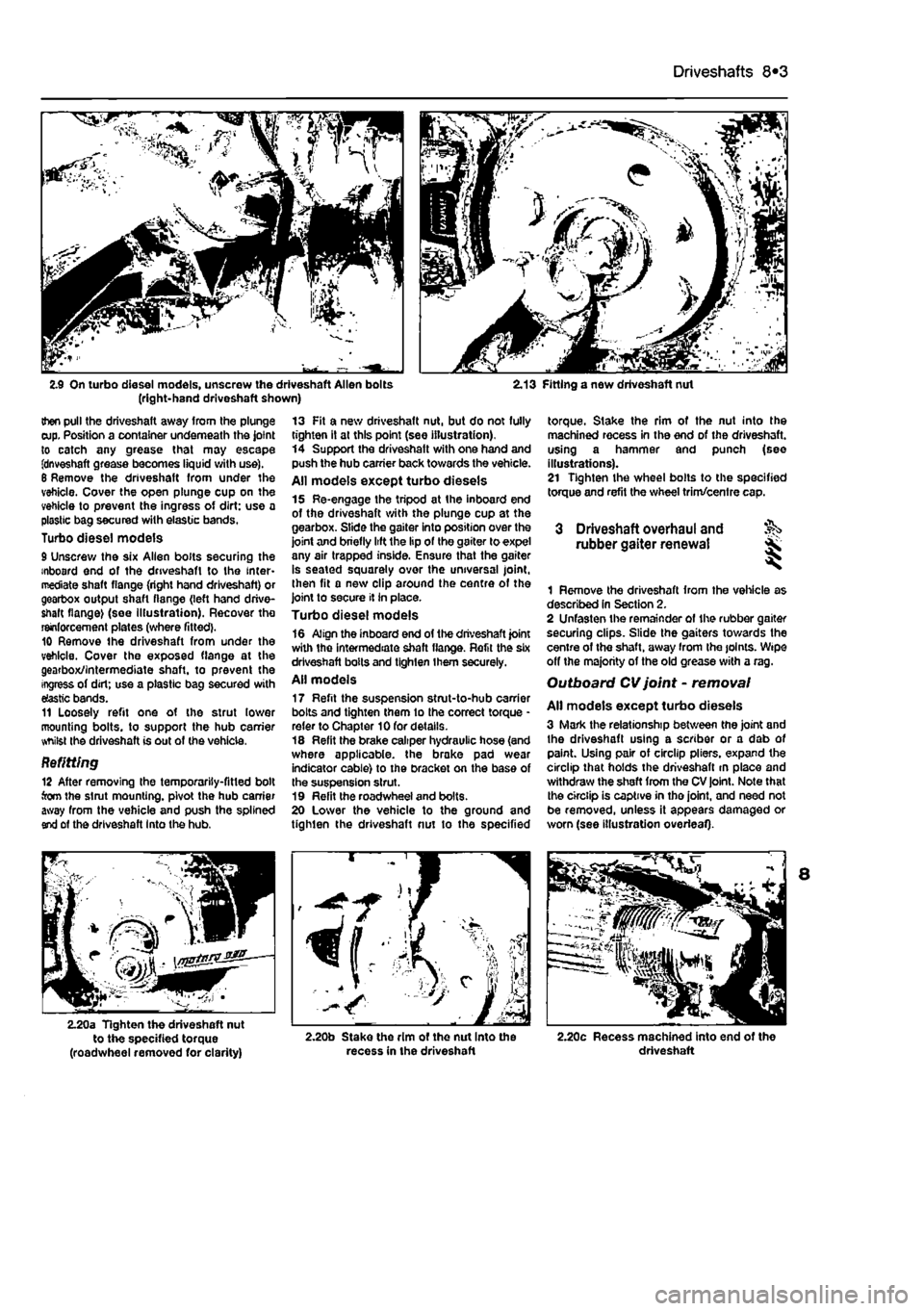
2.9 On turbo diesel models, unscrew the driveshaft Allen bolts (right-hand driveshaft shown) 2.13 Fitting a new driveshaft nut
then pull the driveshaft away from the plunge cup. Position a container underneath the joint to catch any grease that may escape fdnveshaft grease becomes liquid with use). 6 Remove the driveshaft from under the vehicle. Cover the open plunge cup on the vehicle to prevent the ingress of dirt: use a plastic bag secured with elastic bands. Turbo diesel models 9 Unscrew the six Allen bolts securing the inboard end of the driveshaft to the inter-mediate shaft flange (right hand driveshaft) or gearbox output shaft flange (left hand drive-shaft flange) (see Illustration). Recover tho reinforcement plates (where fitted). 10 Remove the driveshaft from under the vehicle. Cover the exposed flange at the gearbox/intermediate shaft, to prevent the ingress of dirt; use a plastic bag secured with elastic bands. 11 Loosely refit one of the strut lower mounting bolts, to support the hub carrier whilst the driveshaft is out of the vehicle.
Befitting 12 After removing the temporarily-fitted bolt torn the strut mounting, pivot the hub carrier away from the vehicle and push the splined end of the driveshaft Into the hub.
13 Fit a new driveshaft nut, but do not fully tighten it at this point (see illustration). 14 Support the driveshatt with one hand and push the hub carrier back towards the vehicle. All models except turbo diesels 15 Re-engage the tripod at the inboard end of the driveshaft with the plunge cup at the gearbox. Slide the gaiter into position over the joint and briefly lift the lip of the gaiter to expel any air trapped inside. Ensure that the gaiter is seated squarely over the universal joint, then fit a new clip around the centre of the joint to secure it in place. Turbo diesel models 16 Align the inboard end of the driveshaft joint with the intermediate shaft flange. Refit the six driveshaft bolts and tighten them securely. All models 17 Refit the suspension strut-to-hub carrier bolts and tighten them to the correct torque * refer to Chapter 10 for details. 18 Refit the brake caliper hydraulic hose (and where applicable, the brake pad wear indicator cable) to the bracket on the base of the suspension strut. 19 Refit the roadwheel and bolts. 20 Lower the vehicle to the ground and tighten the driveshaft nut to the specified
torque. Stake the rim of the nut into the machined recess in the end of the driveshaft. using a hammer and punch (see illustrations). 21 Tighten the wheel bolts to the specified torque and refit the wheel trim/centre cap.
3 Driveshaft overhaul and rubber gaiter renewal
1 Remove the driveshaft from the vehicle as described In Section 2. 2 Unfasten the remainder of the rubber gaiter securing clips. Slide the gaiters towards the centre of the shaft, away from Ihe joints. Wipe off the majority of the old grease with a rag. Outboard CV joint - removal
All models except turbo diesels 3 Mark the relationship between the joint and the driveshaft using a scriber or a dab of paint. Using pair of circlip pliers, expand the circlip that holds the driveshaft m place and withdraw the shaft from the CV joint. Note that the circlip is captive in tho joint, and need not be removed, unless it appears damaged or worn (see illustration overleaf).
2.20a Tighten the driveshaft nut to the specified torque (roadwheel removed for clarity) 2.20b Stake the rim ot the nut Into the recess in the driveshaft 2.20c Recess machined into end of the driveshaft
Page 175 of 225
I
8*4 Driveshafts
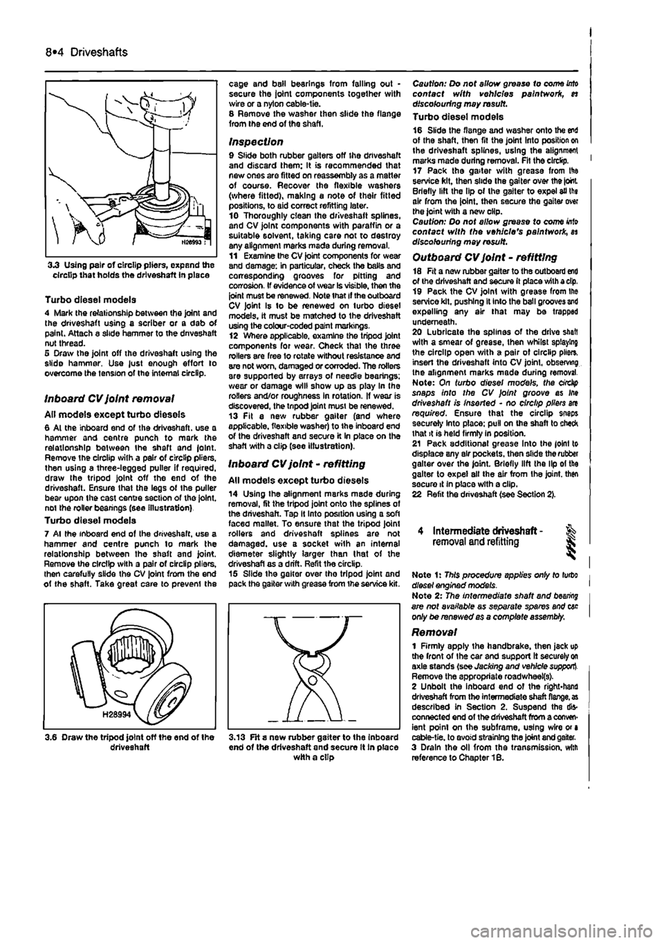
3.3 Using pair of circlip pliers, expand the circlip that holds the driveshaft in place
Turbo diesel models 4 Mark the relationship between the joint and the driveshaft using a scriber or a dab of paint. Attach a slide hammer to the dnveshaft nut thread. 5 Draw the joint off the driveshaft using the slide hammer, Use just enough effort to overcome the tension of the internal circlip.
Inboard CV joint removal All models except turbo dieseis 6 Al the inboard end of the driveshaft. use a hammer and centre punch to mark the relationship between Ihe shaft and |olnt. Remove the circlip with a pair of circlip pliers, then using a three-legged puller if required, draw Ihe tripod joint off the end of the driveshaft. Ensure that the legs of Ihe puller bear upon the cast centre section of the joint, not the roller beanngs (see illustration) Turbo diesel models 7 Al the inboard end of Ihe driveshaft. use a hammer and centre punch lo mark the relationship between the shaft and joint. Remove the circlip with a pair of circlip pliers, then carefully slide the CV joint from the end ot the shaft. Take great care to prevenl the
cage and bail bearings from falling out • secure the joint components together with wire or a nylon cable-tie. 8 Remove the washer then slide the flange from the end of the shaft.
Inspection 9 Slide both rubber gaiters off the driveshaft and discard them: It is recommended that new ones are fitted on reassembly as a matter of course. Recover the flexible washers (where fitted), making a note of their fitted positions, to aid correct refitting later. 10 Thoroughly clean the driveshaft splines, and CV joint components with paraffin or a suitable solvent, taking care not to destroy any alignment marks made during removal. 11 Examine Ihe CV joint components for wear and damage: in particular, check the balls and corresponding grooves for pitting and corrosion. If evidence of wear Is visible, then the joint must be renewed. Note that if the outboard CV joint Is to be renewed on turbo diesel models, it must be matched to the driveshaft using the colour-coded paint markings. 12 Where applicable, examine the tripod joint components for wear. Check thai the three rollers are free lo rotate without resistance and are not worn, damaged or corroded. The rollers are supported by arrays of needle bearings: wear or damage will show up as play In the rollers and/or roughness in rotation. If wear is discovered, the tnpod joint must be renewed. 13 Fit a new rubber gaiter (and where applicable, flexible washer) to the inboard end of the driveshaft and secure it In place on the shaft with a clip (see illustration).
Inboard CV joint - refitting
All models except turbo dieseis 14 Using Ihe alignment marks made during removal, fit the tripod joint onto the splines of the driveshaft. Tap It Into position using a soft faced mallet. To ensure that the tripod Joint rollers and driveshaft splines are not damaged, use a socket with an internal diameter slightly larger than I hat of the driveshafl as a drift. Refit the circlip. 15 Slide the gaiter over tho tripod joint and pack the gaiter with grease from the service kit.
3.6 Draw the tripod joint off the end of the driveshaft 3.13 FH s new rubber gaiter to the inboard end of the driveshaft and secure It in place with a clip
Caution: Do not allow grease to come
into
contact with vehicles paintwork, es discolouring may rasutt. Turbo diesel models 16 Slide the flange and washer onto the end of the shaft, then fit the joint Into position on the driveshaft splines, using the alignment marks made during removal. Fit the circlip. ' 17 Pack the gaiter with grease from His service kit, then slide the gaiter over the joint. Briefly lift the lip of the gaiter to expel ail the air from the joint, then secure the gaiter over the joint with a new clip. Caution: Do not allow grease to come
Into
contact with the vehicle's paintwork, as discolouring may result.
Outboard CV joint - refitting 18 Fit a new rubber gaiter to the outboard end of the driveshaft and secure it place with a dp, 19 Pack the CV joint with grease from Ihe service kit, pushing It into the ball grooves and expelling any air that may be trapped underneath. 20 Lubricate the splines of the drive shaft with a smear of grease, then whilst splaying the circlip open with a pair ot circlip pile*, insert the driveshaft into CV joint, observing the alignment marks made during removal. Note: On turbo diesel models, the circlip snaps into the CV Joint groove as Ifte driveshaft is inserted - no circlip pliers are required. Ensure that the circlip snaps securely Into place: pull on the shaft to check that it is held firmly In position. 21 Pack additional grease Into the joint to displace any air pockets, then slide the rubber gaiter over the joint. Briefly lift the lip ol the gaiter to expel all the air from Ihe joint, then secure it In place with a clip. 22 Refit the driveshaft (see Section 2).
4 Intermediate driveshaft - % removal and refitting J;
Note 1: This procedure applies only to turbo diesel engined models. Note 2: The intermediate shaft and
bearing
are not available as separate spares and cac only be renewed as a comptefe assembly.
Removal 1 Firmly apply the handbrake, then jack up the front of Ihe car and support It securely
on
axle stands (see Jacking and vehicle support). Remove the appropriate roadwheei(s). 2 Unbolt the inboard end of the right*hand driveshaft from the intermediate shaft
flange, as
described In Section 2. Suspend the dis-connected end of the driveshaft from a conven-ient point on the subframe, using wire or a cable-tie. to avoid straining the joint and gaiter. 3 Drain the oil from the transmission, with reference to Chapter 1B.
Page 177 of 225
9«1
Chapter 9
Braking system
Contents
Brake disc - inspection, removal and refitting 4 Brake fluid level check See Weekly checks Brake fluid renewal See Chapter 1A or 1B Brake warning lamp check See Chapter 1A or 1B Front brake caliper - removal, overhaul and refitting 3 Front brake pad check See Chapter 1A or 1B Front brake pads - renewal 2 General information 1 Handbrake - checking and adjustment 9
Handbrake cables - removal and refitting 10 Hydraulic pipes end hoses - renewal 13 Hydraulic system - bleeding 11 Master cylinder - removal and refitting 12 Roar brake shoe check See Chapter 1A or 1B Rear brake shoes - renewal 5 Rear brake drums - removal, inspection and refitting 6 Rear wheel cylinder - removal, overhaul and refitting 7 Stop-light switch - adjustment, removal and refitting 6
Degrees of difficulty
Easy, suitable
far
novice with Sttle
experience ^
Fairly
easy,
suitable ^ (orbeginnerwith ®
some
experience
Fairly difficult, suitable
for
compe«ent ^ CHYmechanlc ^
Difficult, suitable for
experienced DIY « mechanic ^
Very difficult, ^
suitable
for
expert DIY
or professional ^
Specifications
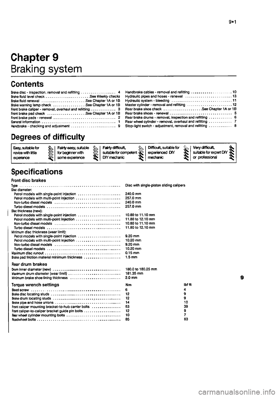
Front disc brakes Type Disc with single-piston sliding calipers Disc diameter Petrol models with single-point Injection 240.0 mm Petrol models with multi-point Injection 257.0 mm Non-turbo diesel models 240.0 mm Turbodieselmodels 257.0 mm Disc thickness (new); Petrol models with single-point injection 10.80 to 11.10 mm Petrol models with multi-point Injection 11.80 to 12.10 mm Non-turbo diesel models 10.80 to 11.10 mm Turbodieselmodels 11.80 to 12.10 mm Minimum disc thickness (wear limit): Petrol models with single-pant Injection 9.20 mm Petrol models with multi-point Injection 10.20 mm Non-turbo diesel models 9.20 mm Turbo diesel models 10.20 mm Maximum disc runout 0.15 mm Brake pad friction material minimum thickness 1.5 mm
Rear drum brakes Drum Inner diameter (new) 180.0 to 180.25 mm Maximum drum diameter (wear limit) 181.35 mm Minimum brake shoe lining thickness 2.0 mm
Torque wrench settings Nm ibf ft
Bfeed
screw 6 4 Brake disc locating studs 12 9 Brake drum locating studs 12 9 Brake pipe and hose unions 14 10 Front caliper mounting bracket-to-hub carrier bolts 53 39 Front caliper-to-caliper bracket guide pin bolts 12 9 fleer wheel cylinder mounting boils 10 7 Roadwheel bolts 85 63
Page 189 of 225
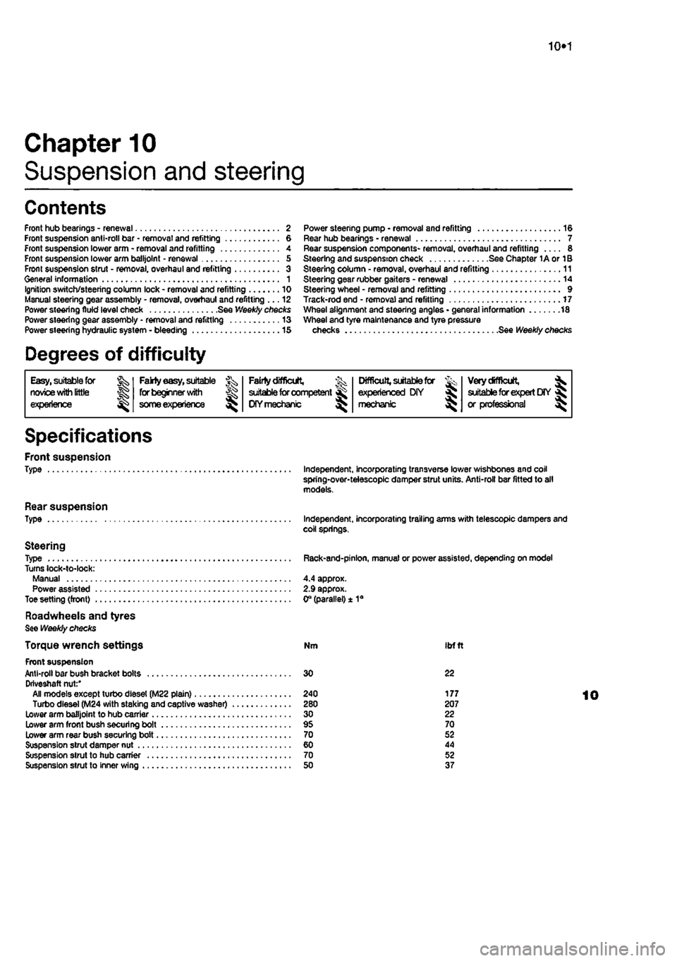
10*1
Chapter 10
Suspension and steering
Contents
Front hub bearings - renewal 2 Front suspension anti-roll bar • removal and refitting 6 Front suspension lower arm - removal and refitting 4 Front suspension lower arm balljolnt - renewal 5 From suspension strut - removal, overhaul and refitting 3 General information 1 Ignition switch/steering column lock - removal and refitting 10 Manual steering gear assembly - removal, overhaul and refitting ... 12 Power steering fluid level check See Weekly checks Power steering gear assembly - removal and refitting 13 Power steering hydraulic system - bleeding 15
Degrees of difficulty
Power steering pump • removal and refitting 16 Rear hub bearings - renewal 7 Rear suspension components- removal, overhaul and refitting 8 Steering and suspension check See Chapter 1A or 1B Steering column - removal, overhaul and refitting 11 Steering gear rubber gaiters - renewal 14 Steering wheel - removal and refitting 9 Track-rod end - removal and refitting 17 Wheel alignment and steering angles • general information 18 Wheel and tyre maintenance and tyre pressure checks See Weekly checks
Easy, suitable for nowoe with little
Jg experience ^
Fakty easy,
suitable for beginner
with
J£>
some experience
^
FaMy difficult,
% suitable for competent ^
DIY mechanic
^
Difficult,
suitable for & experienced DIY « mechsmc ^
Very difficult,
^ suitable for expert
DIY
fij or professional ^
Specifications
Front suspension Type
Rear suspension Type
Steering Type Turns lock-to-lock: Manual Power assisted Toe setting (front)
Roadwheeis and tyres See Weekly checks
Torque wrench settings Front suspension Anti-roll bar bush bracket bolts Driveshaft nut:' All models except turbo diesel (M22 plain) Turbo diesel (M24 with staking and captive washer) Lower arm balljoint to hub carrier Lower arm front bush securing bolt Lower arm rear bush securing bolt Suspension strut damper nut Suspension strut to hub carrier Suspension strut to inner wing
Independent, incorporating transverse lower wishbones and coil spring-over-teiescopic damper strut units. Anti-roll bar fitted to all models.
Independent, incorporating trailing arms with telescopic dampers and coil springs.
Rack-and-pinlon, manual or power assisted, depending on model
4.4 approx. 2.9 approx. 0° (parallel) ± 1a
Nm ibfft
30 22
240 177 280 207 30 22 95 70 70 52 60 44 70 52 50 37