warning light FIAT PUNTO 1999 176 / 1.G Owner's Manual
[x] Cancel search | Manufacturer: FIAT, Model Year: 1999, Model line: PUNTO, Model: FIAT PUNTO 1999 176 / 1.GPages: 225, PDF Size: 18.54 MB
Page 122 of 225
4A*2 Fuel system - single-point petrol Injection models
1 General information and precautions
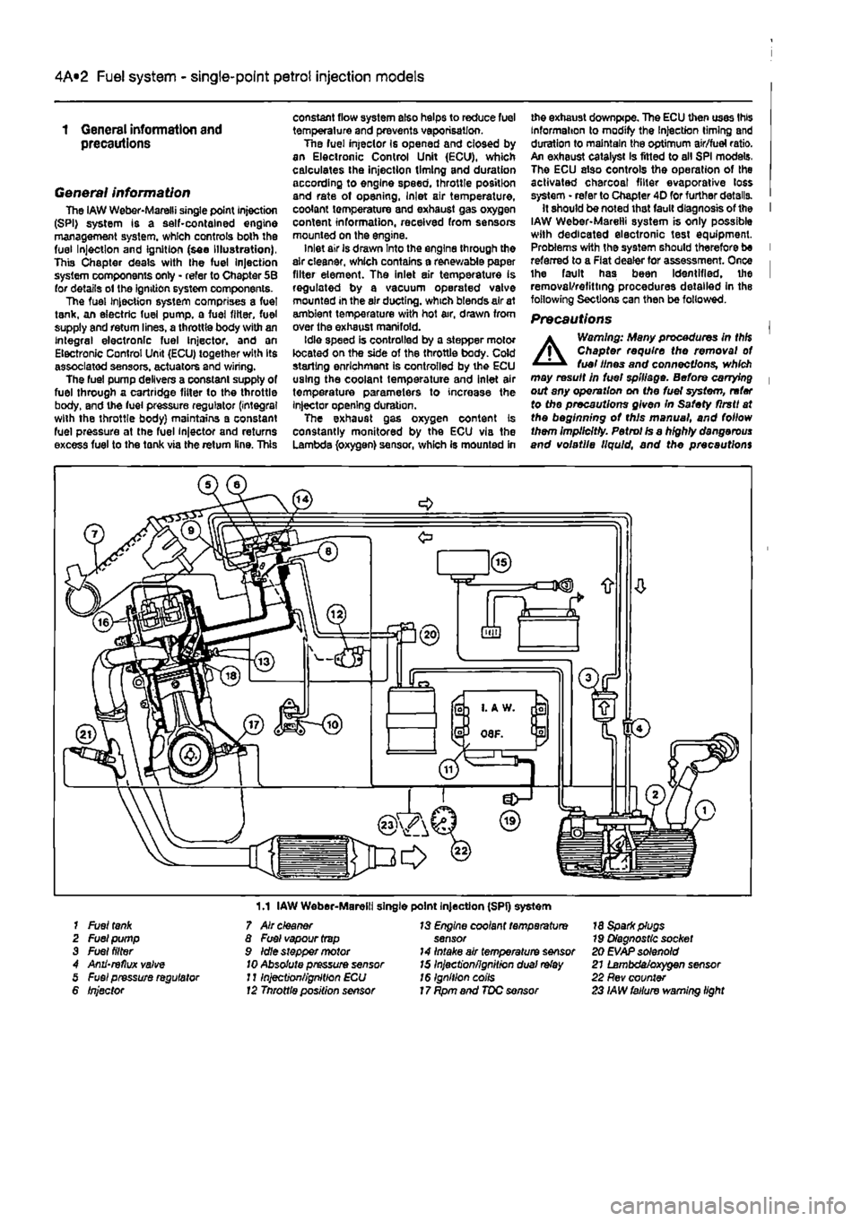
General information The iAW Weber-Marelli single point Injection (SPI) system is a self-contained engine management system, which controls both the fuel Injection and Ignition (see Illustration), This Chapter deals with the fuel Injection system components only - refer to Chapter 5B for details ol the ignition system components. The fuel Injection system comprises a fuel tank, an electric fuel pump, a fuel filter, fuel supply and return lines, a throttle body with an integral electronic fuel Injector, and an Electronic Control Unit (ECU) together with its associated sensors, actuators and wiring. The fuel pump delivers a constant supply of fuel through a cartridge fitter to the throttle body, and the fuel pressure regulator (integral with the throttle body) maintains a constant fuel pressure at the fuel injector and returns excess fuel to the tank via the return line. This
constant flow system also helps to reduce fuel temperature and prevents vaporisation. Tne fuel injeclor Is opened and closed by an Electronic Control Unit (ECU), which calculates the injection timing and duration according to engine speed, throttle position and rate of opening, Inlet air temperature, coolant temperature and exhaust gas oxygen content information, received from sensors mounted on the engine. inlet air is drawn Into the engine through the air cleaner, which contains a renewable paper filter element. The inlet air temperature is regulated by a vacuum operated valve mounted in the air ducting, which blends air at ambient temperature with hot air, drawn from over the exhaust manifold. Idle speed is controlled by a stepper motor located on the side of the throttle body. Cold starling enrichment is controlled by the ECU using the coolant temperature and inlet air temperature parameters to increase the injector opening duration. The exhaust gas oxygen content is constantly monitored by the ECU via the Lambda (oxygen) sensor, which is mounted in
me exhaust downpipe. The ECU then uses this Information to modify the Injection timing and duration to maintain the optimum air/fuel ratio. An exhaust catalyst Is fitted to all SPI models. The ECU also controls the operation of the activated charcoal filter evaporative loss system • refer to Chapter 4D for further details. It should be noted that fault diagnosis of the I IAW Weber-Marelli system is only possible with dedicated electronic test equipment. Problems with the system should therefore be I referred to a Flat dealer for assessment. Once i the fault has been Identified, the I removal/refitting procedures detailed in the following Sections can then be followed.
Precautions |
A
Warning: Many procedures in thH Chapter require the removal ot fuel lines and connections, which may result in fuel spillage. Before carrying | out any operation on Me fuel system, refer to the precautions given In Safety flrstt at the beginning ot this manual, and follow them Implicitly. Petrol Is a highly dangerous and volatile liquid, and the precautions
1.1 IAW Weber-Marelli single point Injection (SPI) system 1 Fuel
tank
2 Fuel pump 3 Fuel filter 4 Anii'reflux valve 5 Fuel pressure regulator 6 Injector
7 Air cleaner 8 Fuel vapour
trap
9 Idle stepper motor
10
Absolute pressure sensor J11njection/ignition ECU 12 Tnrottle position sensor
13 Engine coolant temperature sensor 14 Intake air temperature sensor 15 Inject'onfignitron dual
relay
16 Ignition coils 17 Rpm and TDC sensor
18 Spark plugs 79 Diagnostic socket 20 EVAP solenoid 21 Lambda/oxygen sensor 22 Rev counter 23 IAW failure warning light
Page 128 of 225
4A*2 Fuel system -
single-point
petrol Injection models
1 General information and precautions
General information The
LAW
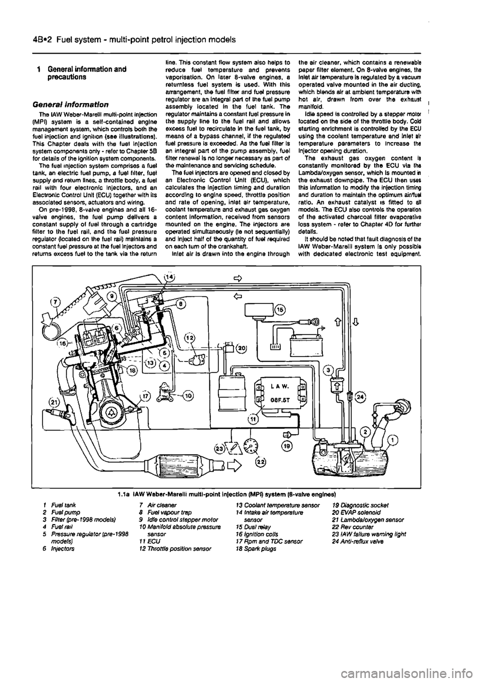
Weber-Maretil multi-point Injection (MPI) system is a self-contained engine management system, which controls both the fuel injoction and Ignition (see Illustrations). This Chapter deals with the fuel Injection system components only - refer to Chapter 5B for details of the ignition system components. The fuel injection system comprises a fuel tank, an electric fuel pump, a fuel filter, fuel supply end return lines, a throttle body, a fuel rail with four electronic Injectors, and an Electronic Control Unit (ECU) together with its associated sensors, actuators and wiring. On pre-1998, 8-valve engines and all 16-valve engines, the fuel pump delivers a constant supply of fuel through a cartridge filter to the fuel rail, and the fuel pressure regulator (located on Ihe fuel rail) maintains a constant fuel pressure at the fuel Injectors and returns excess fuel to the tank via the return
line, This constant flow system also helps to reduce fuel temperature and prevents vaporisation. On later 8-valve engines, a returnless fuel system is used. With this arrangement, the fuel filter and fuel pressure regulator are an integral part of the fuel pump assembly located In the fuel tank. The regulator maintains a constant fuel pressure in the supply line lo the fuel rail and allows excess fuel to recirculate in the fuel tank, by means of a bypass channel, if the regulated fuel pressure is exceeded. As the fuel filler Is an integral part of the pump assembly, fuel filter renewal Is no longer necessary as part of the maintenance and servicing schedule. The fuel injectors are opened and closed by an Electronic Control Unit (ECU), which calculates the Injection timing and duration according to engine speed, throttle position and rate of opening, inlet air temperature, coolant temperature and exhaust gas oxygen content information, received from sensors mounted on the engine. The injectors are operated simultaneously (le not sequentially) and Inject half of the quantity of fuel required on each turn of the crankshaft. Inlet air Is drawn into the engine through
the air cleaner, which contains a renewable paper filter element. On 8-valve engines, the Inlet air temperature is regulated by a vacuum operated valve mounted in the air ducting, which blends air at ambient temperature with hot air, drawn Irom over the exhaust | manifold. Idle speed Is controlled by a stepper motor 1 located on the side of the throttle body. Cold storting enrichment is controlled by the ECU using the coolant temperature and Inlet air temperature parameters to Increase the Injector opening duration. The exhaust gas oxygen content it constantly monitored by the ECU via the Lambda/oxygen sensor, whioh Is mounted in the exhaust downpipe. The ECU then uses this Information to modify the Injection timing and duration to maintain the optimum air/fuel ratio. An exhaust catalyst is fitted to all models. The ECU also controls the operation of the activated charcoal filler evaporative loss system - refer to Chapter 4D for further details. It should be noted that fault diagnosis of the IAW Weber-Marelll system Is only possible with dedicated electronic test equipment.
1.1a IAW Weber-Marelii multt-point Injection (MPi) system (8-valve engines) f Fuel
tank
7 Air
cleaner
13 Coolant temperature sensor 19 Diagnostic socket 2 Fuel pump 8 Fuel vapour trvp 14 Intake air temperature 20
EVAP
solenoid 3 Filter (pre-1998 models) 9 Idle control stepper motor sensor 21 Lambda/oxygen sensor 4 Fuel
rail
10 Manifold absolute pressure 15 Duel
relay
22 Rev counter 5 Pressure regulator
(pre-1998
sensor 16 Ignition colls 23 IAW failure warning light models)
11 ECU
17 Rpm and TDC sensor 24 Anti-refhjx
valve
6 Injectors 12 Throttle position sensor 18 Spark piugs
Page 129 of 225
4A*2 Fuel system -
single-point
petrol Injection models
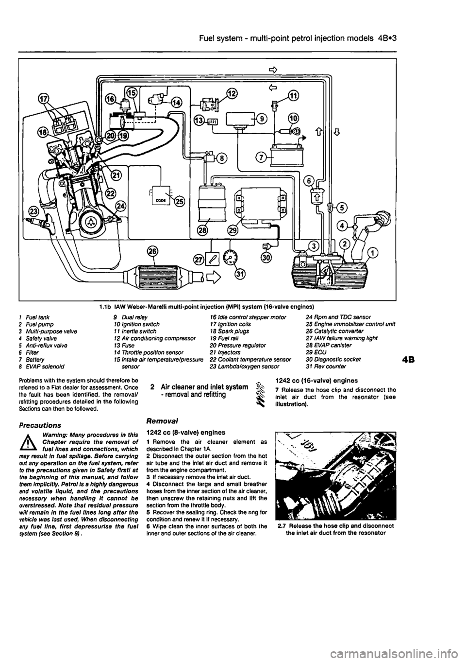
1.1b IAW Weber-Marelli multi-point injection (MPI) system (16-valve engines) J Fuel
tank
2 Fuel pump 3 Multi-purpose
valve
4 Safety
valve
5 Anti-reflux
valve
6 F/fter 7 Battery 8
EVAP
solenoid
9 Dual
relay
10 Ignition switch 111nertia switch
12
Air conditioning compressor
13
Fuse 14 Throttle position sensor
1$
idle control stepper motor 17 Ignition coils 18 Sparkplugs 19 Fuel
rail
20 Pressure regulator 21 Injectors
15
Intake air temperature/pressure 22 Coolant temperature sensor sensor 23 Lambda/oxygen sensor
24 Rpm and TDC sensor 25 Engine immobiliser control unit 26 Catalytic converter 27 IAW failure warning light 28 EVAP canister 29 ECU 30 Diagnostic socket 31 Rev counter
Problems with the system should therefore be referred to a Fiat dealer for assessment. Once the fault has been Identified, the removal/ refitting procedures detailed in the following Sections can then be followed.
Precautions
A
Warning: Many procedures In this Chapter require the removal of fuel lines and connections, which may result In fuel spillage. Before carrying out any operation on the fuel system, refer to the precautions given In Safety flrstl at the beginning of this manual, and follow them implicitly. Petrol Is a highly dangerous and volatile liquid, and the precautions necessary when handling it cannot be overstressed. Note that residual pressure will remain in the fuel lines long after the vehicle was last used, When disconnecting tny fuel line, first depressurise the fuel system {see Section 9).
2 Air cleaner and inlet system Sk - removal
and
refitting ^
Removal
1242 cc (8-valve) engines 1 Remove the air cleaner element as described In Chapter 1A. 2 Disconnect the outer section from the hot air tube and the Inlet air duct and remove it from the engine compartment. 3 If necessary remove the inlet air duct. 4 Disconnect the large and small breather hoses from the inner section of the air cleaner, then unscrew the retaining nuts and lift the section from the throttle body. 5 Recover the sealing ring. Check the nng for condition and renew it it necessary. 6 Wipe clean the inner surfaces of both the Inner and outer sections of the air cleaner,
1242 cc (16-valve) engines 7 Release the hose clip and disconnect the inlet air duct from the resonator (see illustration).
2.7 Release the hose clip and disconnect the inlet air duct from the resonator
Page 141 of 225
Fuel system - diesel models 4C*3
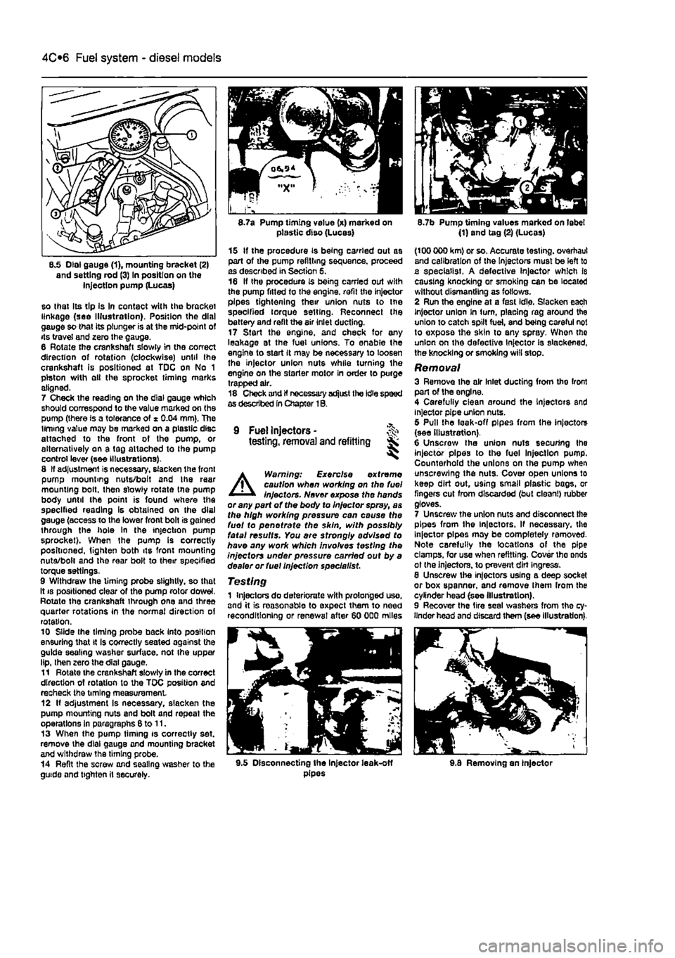
8.5 Dial gauge (1), mounting bracket (2) and setting rod (3) In position on the injection pump (Lucas)
so that Its tip Is In contact with the bracket linkage (see Illustration). Position the dial gauge so that its plunger is at the mid-point of its travel and zero the gauge. 6 Rotate the crankshaft slowly in the correct direction of rotation (clockwise) until the crankshaft is positioned at TDC on No 1 piston with ell the sprocket timing marks aligned. 7 Check the reading on the dial gauge which should correspond to the value marked on the pump (there is a tolerance of * 0.04 mm). The timing value may be marked on a plastic disc attached to the front of the pump, or alternatively on a tag attached to Ihe pump control lever (see illustrations). 8 If adjustment is necessary, slacken the front pump mounting nuts/bolt and the raar mounting bolt, then slowly rotate tne pump body until the point is found where the specified reading is obtained on the dial gauge (access to the lower front bolt is gained through the hole in the injection pump sprocket). When the pump Is correctly positioned, tighten both its front mounting nuta/bolt and the rear bolt to their specified torque settings. 9 Withdraw the timing probe slightly, so that it
8.7a Pump timing value (x) marked on plastic diso (Lucas)
15 If the procedure is being carried out as part of the pump refilling sequence, proceed as described in Section 5. 16 If the procedure is being carried out with the pump fitted to the engine, refit the injector pipes tightening their union nuts to the specified torque setting. Reconnect the battery and refit the air inlet ducting. 17 Start the engine, and check for any leakage at the fuel unions. To enable the engine to start it may be necessary to loosen tho injector union nuts while turning the engine on the starter motor in order to purge trapped air. 18 Check and If necessary adjust the Idle speed as described In Chapter 1B.
9 Fuel Injectors -testing, removal and refitting Sk ^
A
Warning: Exercise extreme caution when working on the fuel injectors. Never expose the hands or any part of the body to Injector spray, as the high working pressure can cause the fuel to pen ot rate the skin, with possibly fatal results. You are strongly advised to have any work which involves testing the injectors under pressure carried out by a dealer or fuel Injection specie list.
Testing 1 Injectors do deteriorate with prolonged uso, and it is reasonable to expect them to need reconditioning or renewal after 60 000 miles
8.7b Pump timing values marked on label (1) and tag (2) (Lucas)
(100 000 km) or so. Accurate testing, overhaul and calibration of the Injectors must be left to a specialist. A defective injector which Is causing knocking or smoking can be located without dismantling as follows. 2 Run the engine at a fast idle. Slacken each Injector union In turn, placing rag around the union to catch spilt fuel, and being careful not to exposa the skin to any spray. When tho union on the defective Injector is slackened, the knocking or smoking will stop.
Removal 3 Remove ihe air Inlet ducting from tho front part of the onglne. 4 Carefully clean around the Injectors and injector pipe union nuts. 5 Pull the leak-off pipes from the injectors (see illustration). 6 Unscrow the union nuts securing Ihe injector pipes to the fuel Injection pump. Counterhold the unions on the pump when unscrewing the nuts. Cover open unions lo keep dirt out, using small plastic bags, or fingers cut from discarded (but clean!) rubber gloves. 7 Unscrew the union nuts and disconnect the pipes from the ln|ectors, If necessary, the Injector pipes may be completely removed-Note carefully the locations of the pipe clamps, for use when refitting. Cover tho onds ot (he injectors, to prevent dirt ingress. 8 Unscrew the injectors using a deep socket or box spanner, and remove Ihem from the cylinder head (see Illustration). 9 Recover the tire seal washers from the cy-linder head and discard them (see illustration).
9.5 Disconnecting the Injector leak-off pipes 9.8 Removing an injector
Page 143 of 225
Fuel system - diesel models 4C*3
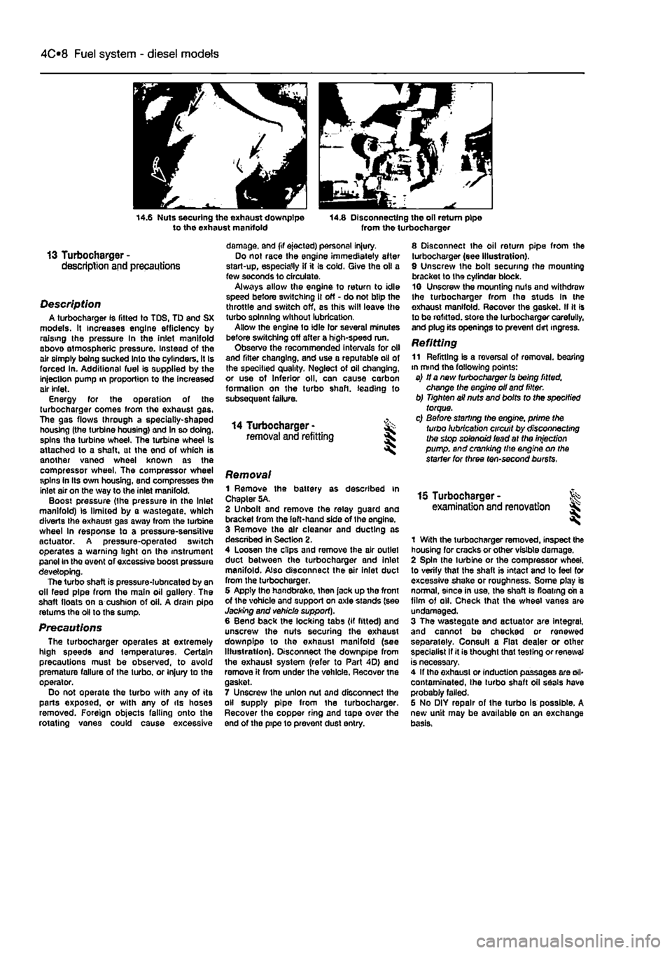
14.6 Nuts securing the exhaust downpipe to the exhaust manifold 14.8 Disconnecting the oil return pipe from tho turbocharger
13 Turbocharger -description and precautions
Description A turbocharger 1$ fitted to TDS, TD and SX models. It increases engine efficiency by raising the pressure In the inlet manifold above atmospheric pressure. Instead of the air simply being sucked Into the cylinders. It Is forced in. Additional fuel is supplied by the injection pump in proportion to the increased air inlet. Energy for the operation of the turbocharger comes from the exhaust gas. The gas flows through a specially-shaped housing (the turbine housing) and In so doing, spins the turbine wheel. The turbine wheel is attached lo a shaft, at the end of which is another vaned wheel known as the compressor wheel, The compressor wheel spins in Its own housing, snd compresses the inlet air on the way to the inlet manifold. Boost pressure (the pressure in the Inlet manifold) is limited by a wastegate, which diverts Ihe exhaust gas away from the turbine wheel In response to a pressure-sensitive actuator. A pressure-operaled switch operates a warning light on the instrument panel in the event of excessive boost pressure developing. The turbo shaft is pressure-lubricated by an oil feed pipe from the main oil gallery The shaft floats on a cushion of oil. A drain pipo returns the oil to the sump.
Precautions The turbocharger operates at extremely high speeds and temperatures. Certain precautions must be observed, to avoid premature failure of the turbo, or injury to the operator. Do not operate the turbo with any of its parts exposed, or with any of ils hoses removed. Foreign objects falling onto the rotating vanes could cause excessive
damage, and (if ejected) personal injury. Do not race the engine immediately after start-up, especially if it Is cold. Give the oil a few seconds lo circulate. Always allow the engine to return to idle speed before switching il off - do not blip the throttle and switch off, as this will leave the turbo spinning without lubrication. Allow the engine to idle lor several minutes before switching off after a high-speed run. Observe the recommended intervals for oil and filter changing, and use a reputable oil of the specified quality. Neglect of oil changing, or use of Inferior oil, can cause carbon formation on the turbo shaft, leading to subsequent failure.
14 Turbocharger -removal and refitting
8 Disconnect the oil return pipe from the turbocharger (see Illustration). 9 Unscrew the bolt securing the mounting bracket to the cyfindar block. 10 Unscrew the mounting nuts and withdraw the turbocharger from the studs in Ihe exhaust manifold. Recover the gasket. II It Is to be refitted, store the turbocharger carefully, and plug its openings to prevent dirt ingress.
Refitting 11 Refitting Is a reversal of removal, bearing in mind the fallowing points: a) if a new turbocharger Is being fitted, change the engine oil and filter. b) Tighten ail nuts and bolts to the specified torque. c) Before starting the engine, prime the turbo lubrication circuit by disconnecting the stop solenoid iead at the injection pump, and cranking the engine on the starter for three ten-second bursts.
Removal 1 Remove the battery as described in Chapter 5A. 2 Unbolt and remove the relay guard and bracket from the left-hand side of Ihe engine. 3 Remove the air cleaner and ducting as descnbed in Section 2. 4 Loosen the clips and remove the air outlet duct between tho turbocharger and inlet manifold. Also disconnect the air inlet duct from the turbocharger. 6 Appty the handbrake, then jack up tho front of the vohicle and support on axle stands (see Jacking and vehicle support). 6 Bend back the locking tabs (if fitted) and unscrew the nuts securing the exhaust downpipe lo the exhaust manifold (see Illustration). Disconnect the downpipe from the exhaust system (refer to Part 4D) end remove it from under the vehicle. Recover tne gasket. 7 Unscrew ihe union nut and disconnect the oil supply pipe from the turbocharger. Recover the copper ring and tape over the end of the pipe 10 prevent dust entry.
15 Turbocharger -examination and renovation l
1 With the turbocharger removed, inspect the housing for cracks or other visible damage. 2 Spin the turbine or the compressor wheel, to verify that the shaft is intact and to feel for excessive shake or roughness. Some play is normal, since in use, the shaft is floating on a film of oil. Check that the wheel vanes are undamaged. 3 The wastegate and actuator are Integral, and cannot be checked or renewed separately. Consul! a Flat dealer or other specialist If it is thought that testing or renewal is necessary. 4 If tho exhaust or induction passages are ail* contaminated, Ihe turbo shaft oil seals have probably failed. 6 No DIY repair of the turbo is possible. A new unit may be available on an exchange basis,
Page 150 of 225
5A«2 Starting and charging systems
Maintenance-free battery -charging Note: The following is intended as a guide only. Always refer to the manufacturer's recommendations (often printed on a label attached to the battery) before charging a battery. 13 This battery type takes considerably longer lo fully recharge than the standard type, the time taken being dependent on the extent of discharge, but it can take anything
up
to three days. 14 A constant voltage type charger is required, tooe set, when connected, to 13.9 to 14.9 votts wth a charger current below 25 amps. Using
mis
method, the battery should be usable within three hours, giving a voltage reading of 12.5 vofts. but this Is for a partially discharged battery and, as mentioned, full charging can
take
considerably longer. 15 If Ihe battery is to be charged from a fully discharged state {condition reading loss lhan 12.2 volts), have it recharged by your FIAT dealer or local automotive electrician, as Ihe charge rate is higher and constant super-vision during charging Is necessary.
3 Battery -removal and refitting
Note: Refer to Disconnecting the battery in ifte Reference Section of this manual before proceeding.
Removal 1 Slacken the clamp bolts and disconnect the ctamp from the battery negative (earth) terminal. 2 Remove the insulation cover (where fitted)
and
disconnect the positive terminal lead(s) in
Die same
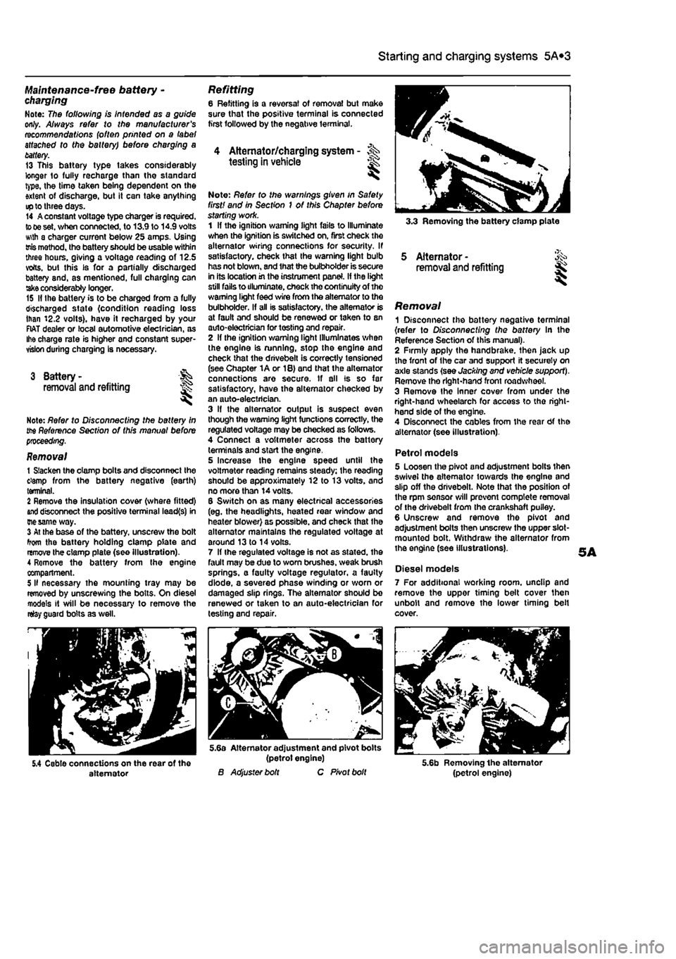
way. 3 At the base of the battery, unscrew the bolt from the battery holding clamp plate and remove the clamp plate (see Illustration). A Remove the battery from Ihe engine compartment. 5 II necessary the mounting tray may be removed by unscrewing the bolts. On diesel models it will be necessary to remove the relay guard bolts as well.
Refitting 6 Refitting is a reversal of removal but make sure that the positive terminal is connected first followed by the negative terminal.
4 Alternator/charging system - >%•> testing in vehicle
Note: Refer to the warnings given in Safety first! and in Section 1 of this Chapter before starting work. 1 If the ignition warning light fails to Illuminate when the ignition is switched on, first check the alternator wiring connections for security. If satisfactory, check that the warning light bulb has not blown, and that the bulbholder is secure in its location in the instrument panel. If the light still fails to illuminate, check the continuity of the warning light feed wire from the alternator to the bulbholder. If all is satisfactory, the alternator is at fault and should be renewed or taken to an auto-electrician for testing and repair. 2 If the ignition warning light Illuminates when the engine Is running, stop the engine and check that the drivebelt is correctly tensioned (see Chapter 1A or 18) and that the alternator connections are secure. If all is so far satisfactory, have the alternator checked by an auto-electrician. 3 If the alternator output is suspect even though the warning light functions correctly, the regulated voltage may be checked as follows. 4 Connect a voltmeter across the battery terminals and start the engine. 5 Increase the engine speed until the voltmeter reading remains steady; the reading should be approximately 12 to 13 volts, and no more than 14 volts. 6 Switch on as many electrical accessories (eg. the headlights, heated rear window and heater blower) as possible, and check that the alternator maintains the regulated voltage at around 13 to 14 volts. 7 If ihe regulated voltage is not as stated, the fault may be due to worn brushes, weak brush springs, e faulty voltage regulator, a faulty diode, a severed phase winding or worn or damaged slip rings. The alternator should be renewed or taken to an auto-electrician for testing and repair.
3.3 Removing the battery clamp plate
5 Alternator -removal and refitting
Removal 1 Disconnect the battery negative terminal {refer to Disconnecting the battery In the Reference Section of this manual). 2 Firmly apply the handbrake, then jack up the front of the car and support it securely on axle stands (see Jacking and vehicle support). Remove tho right-hand front roadwheel. 3 Remove Ihe Inner cover from under the right-hand wheelarch for access to tho right-hand side of the engine. 4 Disconnect the cables from the rear Of the alternator (see illustration).
Petrol models 5 Loosen the pivot and adjustment bolts then swivel the alternator towards the engine and slip off the drivebelt. Note that the position of the rpm sensor will prevent complete removal of the drivebelt from the crankshaft puiley. 6 Unscrew and remove the pivot and adjustment bolts then unscrew the upper slot-mounted bolt. Withdraw the alternator from the engine (see illustrations).
Diesel models 7 For additional working room, unclip and remove the upper timing belt cover then unbolt and remove the lower timing belt cover.
5.4 Cable connections on the rear of the alternator
5.6a Alternator adjustment and pivot bolts (petrol engine) B Adjuster bolt C Pivot bolt 5.6b Removing the alternator (petrol engine)
Page 156 of 225
501
Chapter 5 PartC:
Preheating system - diesel models
Contents
Glow plugs - removal, inspection and refitting 2 Preheating system - description and testing 1 Preheating system control unit - removal and refitting 3
Degrees of difficulty
Ea3y, suitable
for &
novice with little
|| experience ^
Fairty easy,
suitable for beginner with
some experience
jQ
Fairty diffctit, ^
suitable
for competent
DIY
mechanic
Difficult, suitable for
experienced DIY JR mechanic ^
Very difficult, ^ suitable fbrexpertDfY JR or professional ^
Specifications
Torque wrench setting Nm ibf ft Heater glow plugs 15 11
1 Preheating system -description and testing
Description 1 Each swirl chamber has a heater plug (commonly called a glow plug) screwed into it. The plugs are electrically-operated before and during start-up when the engine is cold. 2 Electrical feed to the glow plugs Is controlled by a relay/timer unit. The coolant temperature determines the period of heating that takes place. 3 A warning light in the instnjment panel tells the driver that preheating is taking place. When the light goes out, the engine is ready to be started. The voltags supply to the glow plugs continues for several seconds after the light goes out, If no attempt is made to start, the timer then cuts off the supply, In order to avoid draining the battery and overheating the glow plugs.
Testing 4 If the system malfunctions, testing is ultimately by substitution of known good units, but some preliminary checks may be made as follows. 5 Connect a voltmeter or 12-volt test lamp between the glow plug supply cable and earth (engine or vehicle metal). Make sure that the live connection is kept clear of the engine and bodywork. 6 Have an assistant switch on the ignition, and check that vottage is applied to the glow plugs. Note the time for which the warning light Is lit. and the total time for which voltage Is applied before the system cuts out. Switch off the ignition. 7 At an under-bonnet temperature of 20°C. typical times noted should be 5 or 6 seconds for warning light operation, followed by a further 10 seconds supply after the light goes out. Warning light time will increase with lower temperatures and decrease with higher temp-eratures.
8 If there Is no supply at all, the relay or associated winng is at fault. 9 To locate a defective glow plug, disconnect the main supply cable and the interconnecting strap from the top of the glow plugs. Be careful not to drop the nuts and washers. 10 Use a continuity tester, or a 12-voH test lamp connected to the battery positive terminal, to check for continuity between each glow plug terminal and earth. The resistance of a glow plug in good condition is very low (less than 1 ohm), so if the test lamp does not light or the continuity tester shows a high resistance, the glow plug is certainly defective. 11 If an ammeter is available, the current draw of each glow plug can be checked. After an initial surge of 15 to 20 amps, each plug should draw approximately 12 amps. Any plug which draws much more or less than this is probably defective. 12 As a final check, the glow plugs can be removed and Inspected as described in the following Section.
Page 165 of 225
7A«4 Manual transmission
33 Remove lha air cleaner front section and air ducting with reference to Chapter 4C. Also disconnect the injection pump vacuum pipe from the clips on the left-hand end of the cylinder head. This work is necessary in order to fit the engine hoist 34 Support the weight of the engine using a hoist attached to the engine lifting eyes, or alternatively use a trolley Jack and block of wood beneath the engine. 35 Unscrew the nuts securing the downpipe to the exhaust manifold, then lower it and support on an axle stand. Recover the gasket. 36 Unscrew the starter motor mounting bolts and support the starter motor to one side. 37 Disconnect the wiring from the reversing light switch on the front of the transmission. 38 Unscrew the nut and disconnect the earth cable from its stud. 39 Trace the wiring back from the electronic speedometer sensor and disconnect the connector located on the left-hand side ot the engine. If a mechanical speedometer Is fitted unscrew the knurled collar and disconnect the cabte from the transmission. 40 Unbolt and remove the transmission lower cover. 41 Using an Allen key unscrew the bolts securing the inner end of the left-hand driveshaft to the transmission flange. Remove the bolts and recover the spacer plates. Support the driveshaft on an axle stand. 42 Unscrew and remove the bolts securing the left-hand swivel hub assembly to the front suspension strut, then separate the components and support the swivel hub on an axle stand. 43 Move the swrvel hub assembly outwards and support the driveshaft away from Ihe transmission. 44 Using an Allen key unscrew the bolts securing the Inner end of the right-hand driveshaft to the intermediate shaft flange. Remove the bolts and recover the spacer plates. Support the driveshaft on an axle stand. 45 Remove the intermediate driveshaft with reference to Chapter 8. 46 Working beneath the vehicle, unscrew the bolts securing the rear engine mounting to the underbody then unscrew the bolts securing the mounting to the transmission and withdraw the mounting assembly from under the vehicle.
47 Unscrew the bolts securing the left-hand engine/transmission mounting to the body then unscrew Ihe bolts from the transmission and remove the mounting. 48 Support the weight of the transmission on a trolley jack then unscrew the remaining nut and bolts from the bellhousing and pull the transmission away from the engine.
A
Warning: Support the trans-mission to ensure that It remains steady o/i the jack head. Keep the transmission level until the Input shaft
1$
fully withdrawn from the clutch friction plate.
Refitting 48 Refitting is a reversal of the removal procedure, but note the following points. a) Appiy a smear* of high-meiting-point grease to the clutch friction piate splines; take care to avoid contaminating the friction surfaces. b) Tighten all bolts to the specified torque. c) Fit new clips to secure the driveshaft gaiters to the transmission output shafts. d) Adjust the clutch cable (where applicable) as described In Chapter 6.
4 Manual transmission overhaul -general Infomtatlon
Overhauling a manual transmission is a difficult and Involved Job for the DIY home mechanic. In addition to dismantling and reassembling many small parts, clearances must be precisely measured and, if necessary, changed by selecting shims and spacers. Internal transmission components are also often difficult to obtain, and in many Instances, extremely expensive. Because of this, If the transmission develops a fault or becomes noisy. Ihe best course of action is to have the unit overhauled by a specialist repairer, or to obtain an exchange reconditioned unit. Nevertheless, it is not impossible for the more experienced mechanic to overhaul the transmission, provided the special tools are available, and the Job is done in a deliberate step-by-step manner, so that nothing is overlooked.
The tools necessary for an overhaul include internal and external clrclip pliers, bearing pullers, a slide hammer, a sat of pin punches, a dial test Indicator, and possibly a hydraulic press. In addition, a large, sturdy workbench 8od a vice will be required. During dismantling o1 the transmission, make careful notes of how each component
1$
fitted, to make reassembly easier and more accurate. Before dismantling the transmission, it will help if you have some idea what area is malfunctioning. Certain problems can be closely related to specific areas In the transmission, which can make component examination and replacement easier. Refer to the Fault Finding Section at the end of this manual for more Information.
5 Reversing light switch -testing, removal and refitting ||
Testing 1 The reversing light circuit is controlled by a plunger-type switch screwed into the front of the transmission casing. If a fault develops, first ensure that Ihe circuit fuse has not blown. 2 To test the switch, disconnect the wiring connector, and use a multimeter (set to the resistance function) or a battery-and-bulb test circuit to check that there is continuity between the switch terminals only when reverse gear is selected. If this is not the case, and there are no obvious breaks or other damage to the wires, the switch is faulty, and must be renewed.
Removal 3 Access to the reversing light switch Is best achieved from under the vehicle. Apply the handbrake then jack up Ihe front of the vehicle and support on axle stands (see Jacking and vehicle support). 4 Disconnect the wiring connector, then unscrew It from the transmission casing.
Refitting 5 Refit the switch and tighten securely. 6 Reconnect the wiring then lower the vehicle to the ground.
Page 168 of 225
Automatic transmission 7B*3
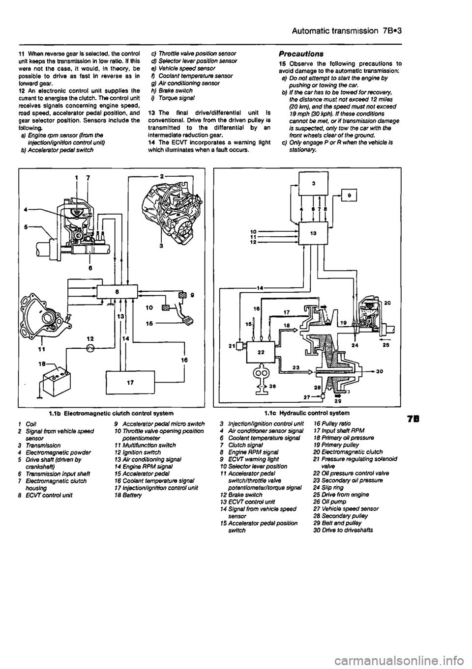
11 When reverse gear Is selected, the control unit keeps the transmission In tow ratio, if this were not the case, it would, In theory, be possible to drive as fast In reverse as in forward gear. 12 An electronic control unit supplies the current to energise the clutch. The control unit receives signals concerning engine speed, road speed, accelerator pedal position, and gear selector position, Sensors include the following. a) Engine rpm sensor (from the Injection/ignition control unit) b) Accelerator pedal switch
c) Throttle valve position sensor d) Selector lever position sensor e) Vehicle speed sensor f) Coolant temperature sensor g) Air conditioning sensor h) Brake switch I) Torque signal
13 The final drive/differential unit Is conventional. Drive from the driven pulley is transmitted to the differential by an Intermediate reduction gear. 14 The ECVT incorporates a warning light which illuminates when a fault occurs.
Precautions 1$ Observe the following precautions to avoid damage to the automatic transmission: a) Do not attempt to start the engine by pushing or towing the car. b) If the car has to be towed for recovery, the distance must not exceed 12 miles (20
km),
and the speed must not exceed
19
mph
(30 kph).
If these conditions cannot be met, or If transmission damage is suspected, only tow the car with the front wheels clear of the ground. c) Only engage P or R when the vehicle is stationary.
1.1b Electromagnetic f Coil 2 Signal from vehicle speed sensor 3 Transmission 4 Electromagnetic powder 5 Drive shaft (driven by crankshaft) $ Transmission input shaft 7 Electromagnetic clutch housing 8 ECVT control unit
clutch control system 9 Accelerator pedal micro switch 10 Throttle
vafve
opening position potentiometer 11 Multifunction switch 12 Ignition switch
13
Air conditioning
signal
14 Engine PPM
signal
15 Accelerator pedal 16 Coolant temperature signal 17 Injection/ignition control unit 18 8attery
1.1c Hydraulic control system 3 Injection/ignition control unit 4 Air conditioner sensor
signal
6 Coolant temperature signal 7 Clutch signal 8 Engine RPM
signal
9 ECVT warning light 10 Selector lever position 11 Accelerator
pedal
switch/throttle
valve
potentiometer/torque signal 12 Brake switch 13
ECVT
control unit 14 Signal from vehicle speed sensor
15
Accelerator pedal position switch
16 Pulley ratio 17 Input shaft RPM 18 Primary oil pressure
19
Primary pulley 20 Electromagnetic clutch 21 Pressure regulating solenoid valve 22 Oil pressure control valve 23 Secondary oil pressure 24 Slip ring 25 Drive from engine 26 Oil pump 27 Vehicle speed sensor 28 Secondary pulley 29 Belt and pulley 30 Drive to drlveshafts
Page 177 of 225
9«1
Chapter 9
Braking system
Contents
Brake disc - inspection, removal and refitting 4 Brake fluid level check See Weekly checks Brake fluid renewal See Chapter 1A or 1B Brake warning lamp check See Chapter 1A or 1B Front brake caliper - removal, overhaul and refitting 3 Front brake pad check See Chapter 1A or 1B Front brake pads - renewal 2 General information 1 Handbrake - checking and adjustment 9
Handbrake cables - removal and refitting 10 Hydraulic pipes end hoses - renewal 13 Hydraulic system - bleeding 11 Master cylinder - removal and refitting 12 Roar brake shoe check See Chapter 1A or 1B Rear brake shoes - renewal 5 Rear brake drums - removal, inspection and refitting 6 Rear wheel cylinder - removal, overhaul and refitting 7 Stop-light switch - adjustment, removal and refitting 6
Degrees of difficulty
Easy, suitable
far
novice with Sttle
experience ^
Fairly
easy,
suitable ^ (orbeginnerwith ®
some
experience
Fairly difficult, suitable
for
compe«ent ^ CHYmechanlc ^
Difficult, suitable for
experienced DIY « mechanic ^
Very difficult, ^
suitable
for
expert DIY
or professional ^
Specifications
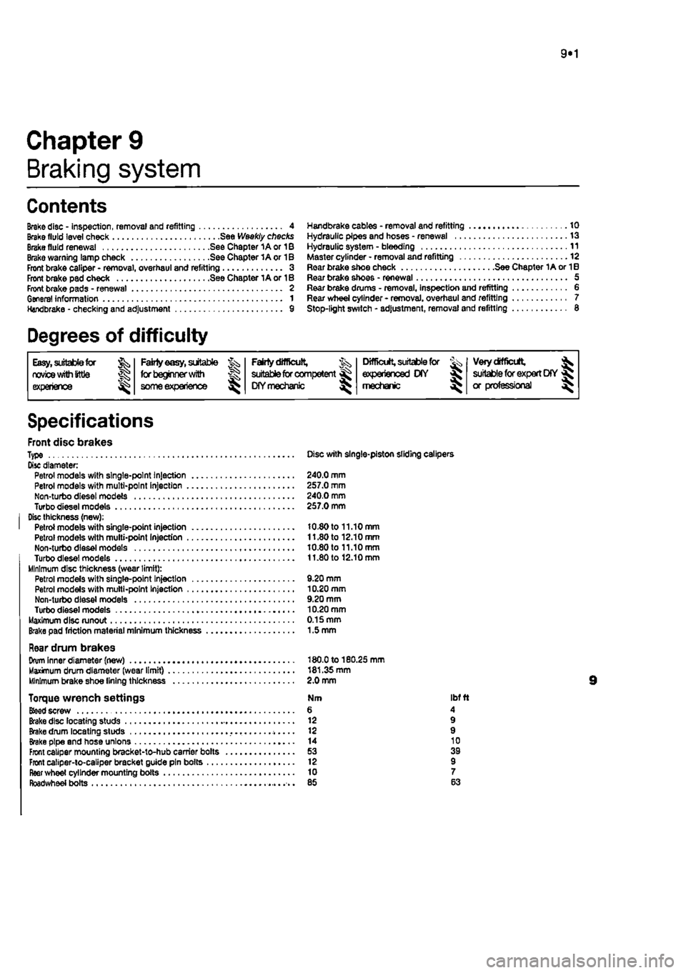
Front disc brakes Type Disc with single-piston sliding calipers Disc diameter Petrol models with single-point Injection 240.0 mm Petrol models with multi-point Injection 257.0 mm Non-turbo diesel models 240.0 mm Turbodieselmodels 257.0 mm Disc thickness (new); Petrol models with single-point injection 10.80 to 11.10 mm Petrol models with multi-point Injection 11.80 to 12.10 mm Non-turbo diesel models 10.80 to 11.10 mm Turbodieselmodels 11.80 to 12.10 mm Minimum disc thickness (wear limit): Petrol models with single-pant Injection 9.20 mm Petrol models with multi-point Injection 10.20 mm Non-turbo diesel models 9.20 mm Turbo diesel models 10.20 mm Maximum disc runout 0.15 mm Brake pad friction material minimum thickness 1.5 mm
Rear drum brakes Drum Inner diameter (new) 180.0 to 180.25 mm Maximum drum diameter (wear limit) 181.35 mm Minimum brake shoe lining thickness 2.0 mm
Torque wrench settings Nm ibf ft
Bfeed
screw 6 4 Brake disc locating studs 12 9 Brake drum locating studs 12 9 Brake pipe and hose unions 14 10 Front caliper mounting bracket-to-hub carrier bolts 53 39 Front caliper-to-caliper bracket guide pin bolts 12 9 fleer wheel cylinder mounting boils 10 7 Roadwheel bolts 85 63