Petrol ron FIAT PUNTO 1999 176 / 1.G Owner's Guide
[x] Cancel search | Manufacturer: FIAT, Model Year: 1999, Model line: PUNTO, Model: FIAT PUNTO 1999 176 / 1.GPages: 225, PDF Size: 18.54 MB
Page 74 of 225
2C*2 Diesel engine in-car repair procedures
1 General information
Using this Chapter Chapter 2 is divided Into four Parts; A. 8, C and 0. Repair operations that cart be carried out with the engine in the vehicle are described In Part A, SOHC (B-valve) petrol engines. Part B, DOHC (16-valve) petrol engines and Part C. diesel engines, Part D covers the removal of the engine/transmission as a unit, and describes the engine dismantling and overhaul procedures. In Parts A. 8 and C. the assumption Is made that the engine is installed in Ihe vehicle, with all anciliaries connected If the engine has been removed for overhaul, the preliminary dismantling information which precedes each operation may be ignored.
Engine description Both normally aspirated (non-turbo) and turbocharged diesel engines are fitted to the Punto range. The engines together with their codes are given in the Specifications at the start of lhis Chapter. The engines are water-cooled, single-overhead camshaft. In-line lour cylinder units with cast-iron cylinder blocks and aluminium-alloy cylinder heads. The engine is mounted transversely at the front of the vehicle, with the transmission bolted to the left-hand side of the engine. The cylinder head carries the camshaft which is driven by a toothed timing belt. It also houses the inlet and exhaust valves which are closed by single coll valve springs and run in valve guides pressed into the cylinder head. The valves are operated by cam followers fitted over each valve, and the clearances are adjusted by shims positioned between the followers and the camshaft lobes. The camshaft is supported by four bearings • the end bearings are machined in the cylinder head and the remaining bearings have caps bolted to the cylinder head. The cylinder head contains integral oiiways which supply and lubricate the camshaft and followers and it also Incorporates renewable swirl chambers. The crankshaft Is supported by five main bearings, and endfloat Is controlled by a thrust bearing fitted on the rear main bearing. All diesel engines are fitted with a brake servo vacuum pump dnven from the left-hBnd end of the camshaft. Engine coolant is circulated by a pump, driven by the auxiliary drivebeit. For details of the cooling system refer to Chapter 3. Lubricant is circulated under pressure by a pump, driven from the front of the crankshaft. Oil is drawn from the sump through a strainer, and then forced through an externally-mounted, replaceable screw-on filter. From there, it is distributed to the cylinder head.
where il lubncates the camshaft journals and followers, and also to the crankcase, where it lubricates the main bearings, connecting rod big- and small-ends, gudgeon pins and cylinder bores. Oil jets are fitted to the base of each cylinder bore - these spray oil onto the underside of the pistons, lo Improve cooling. An oil cooler is also fitted to reduce the temp-erature of oil before it re-enters the engine.
Repair operations possible with the engine in the car The following work can be carried out with the engine in the can a) Compression pressure - testing b) Auxiliary drivebeit - removal and refitting (refer to Chapter rej c) Valve clearances • checking and adjustment (refer to Chapter 1B) d) Camshaft cover - removal and refitting e) Tim/ng belt and covers • removal and refitting 0 Timing belt tensioner and sprockets -removal and refitting g) Cylinder head - removal and refitting' h) Camshaft and cam followers - removal end refitting' I) Camshaft oil seal - renewal j) Crankshaft oil seals - renewal k) Flywheel • removal, inspection and refitting I) Engine mountings - inspection and renewal m)Sump • removal and refitting n) Oil pump and pick-up tube assembly -removal, inspection and refitting 'Cylinder head dismantling procedures are detalfed In Chapter 2D, with details of camshaft and cam follower removal. Note: It ts possible to remove the pistons and connecting rods (after removing the cylinder nead and sump) without removing the engine. However, this is not recommended. Work of this nature is more easily and thoroughly completed with the engine on tho bench as described in Chapter 2D.
2 Location of
TDC
on ^ No
1
cylinder ||
General information 1 The camshaft and fuel Injection pump are driven by the crankshaft, by means of sprockets and a timing belt. All three sprockets rotate in phase with each other and this provides the correct valve and injection pump timing as the engine rotates. When the timing bell is removed during servicing or repair, it is possible for the camshaft, injection pump and crankshaft to rotate independently of each other and the correct timing Is then lost.
2 It
Location of TDC on cylinder No
1
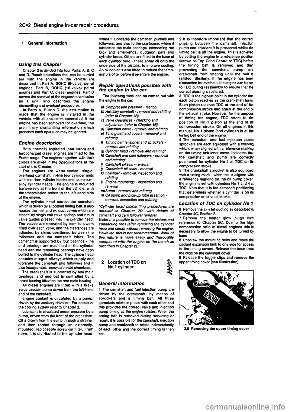
6 Remove the air inlet ducting as described ft Chapter 4C, Section 2. 7 Remove the heater glow plugs with reference to Chapter 5C. Due to the high compression ratio of diesel engines this Is necessary to allow the engine to be turned by hand. 8 Unscrew the mounting bolts and move the coolant expansion tank to one side for access to the timing covers. Release the hose from the clips on Ihe camshaft cover. 9 Release the toggle clips and remove the upper timing cover (see illustration),
2.9 Removing the upper timing cover
Page 91 of 225
2D*10 Engine removal and overhaul procedures
1 General information
Included In (his Part of Chapter 2 are details of removing the engine/transmission from the car and general overhaul procedures for tho cylinder head, cylinder block/crankca9e and all other engine internal components. The information given ranges from advice concerning preparation for an overhaul and the purchase of replacement parts, to detailed step-by-step procedures covering removal, inspection, renovation and refitting of engine Internal components. After Section 5, all instructions are based on the assumption that the engine has been removed from the car. For Information concerning in-car engine repair, as well as the removal and refitting of those external components necessary for full overhaul, refer to Part A, 8 or C of this Chapter (as applicable) and to Section 5. Ignore any preliminary dismantling operations described in Part A. B or C that are no longer relevant onca the engine has been removed from ihe car.
2 Engine overhaul -general information
1 It Is not always easy to determine when, or if, an engine should be completely overhauled, as a number of lectors must be considered. 2 High mileage Is not necessarily an Indication that an overhaul Is needed, while low mileage does not preclude the need for an overhaul. Frequency of servicing Is probably the most important consideration. An engine which has had regular and frequent oil and filter changes, as well as other required maintenance, should give many thousands of miles of reliable service. Conversely, a neglected engine may require an overhaul very early In its life. 3 Excessive oil consumption Is an Indication that piston rings, vaivo seals and/or valve guides are in need of attention. Make sure that oil leaks are not responsible before deciding that the rings and/or guides are worn Perform a compression test, as described In Parts A or B (petrol engines) or C (diesel engines) of this Chapter, to determine the likely cause of the problem. 4 Check the oil pressure with a gauge fitted In place of the oil pressure switch. If it Is extremely low. the main and big-end bearings, and/or the oil pump, are probably worn out. 5 Loss of power, rough running, knocking or metallic engine noises, excessive valve gear noise, and high fuel consumption may also point to Ihe need for an overhaul, especially if
they are all present at the same time. If a complete service does not remedy the situation, major mechanical work is the only solution. 6 An engine overhaul involves restoring ell Internal parts to the specification of a new engine. During an overhaul, the cylinders are rebored (where applicable), the pistons and the piston rings are renewed. New main and big-end bearings are generally fitted; If necessary, the crankshaft may be reground. to restore the journals. 7 The valves are also servrced as well, since they are usually In less-than-perfect condition at this point. While the engine is being overhauled, other components, such as the starter and alternator, can be overhauled as well. The end result should be an as-new engine that will give many trouble-free miles. Note: Critical cooling system components such as the hoses, thermostat and coolant pump should be renewed when an engine is overhauled. The radiator should be checked carefully, to ensure that it is not clogged or leaking. A/so. it Is a good Idea to renew the ofI pump whenever the engine i$ overhauled.
8 Before beginning the engine overhaul, read through tho entire procedure, to familiarise yourself with the scope and requirements of the job. Overhauling an engine is not difficult If you follow carefully all of the instructions, have the necessary tools and equipment, and pay close attention to all specifications. It can, however, be time-consuming. Plan on the car being off the road for a minimum of two weeks, especially If pans must be taken to an engineering wo'kd for repair or reconditioning.
9 Check on the availability of parts and make sure that any necessary special tools and equipment are obtained in advance. Most work can be done with typical hand lools, although a number of precision measuring tools are required (or Inspecting parts to determine if they must be renewed. Often the engineering works will handle the inspection of parts and offer advice concerning reconditioning and renewal, Note: Always wait unt'l the engine has been completely dismantled, and until all components (especially the cylinder block/crankcase and the crankshaft) have been inspected, before deciding what service and repair operations must be performed by an engineering works. The condition of these components will be the major factor to consider when determining whether to overhaul the original engine, or to buy a reconditioned unit. Do not. fh ere tore, purchase parts or have overhaul work done on other components until they have been thoroughly Inspected. As a general rule, time is the primary cost of an overhaul, so it does not pay to fit worn or sub-standard parts.
10 As a final note, to ensure maximum life and minimum trouble from a reconditioned engine, everything must be assembled wilh care, in a spotlessly-clean environment.
3 Engine and transmission removal -methods
and
precautions
1 If you have decided that the engine must be removed for overhaul or major repair work, several preliminary steps should be taken. 2 Locating a suitable place to work is extremely important. Adequate work space, along with storage space for the car, will be needed. If a workshop or garage Is not available, at the very least, a flat, level, clean work surface Is required. 3 Cleaning the engine compartment and engine/transmission before beginning the removal procedure wilt help keep tools clean and organised. 4 An engine hoist or A-frame will also be necessary. Make sure the equipment is rated In excess of the combined weight of the engine and transmission, Safety Ib of primary Importance, considering the potential hazards involved in lifting the engine/transmission out of the car. 5 If this is Ihe first time you have removed
an
engine, an assistant Bhould Ideally be available. Advice and aid from someone more experienced would also be helpful. There are many instances when one person cannot simultaneously perform all of the operations required when lifting the engine out of Ihe vehicle. 6 Plan the operation ahead of time. Before starting work, arrange for the hire of or obtain all of the tools and equipment you will need. Some of the equipment necessary to perform engine/transmission removal and Installation safely and wilh relative ease On addition to an engine hoist) Is as follows: a heavy duly trolley jack, complete sets of spanners and sockets as described in the reference section of this manual, wooden blocks, and plenty of rags and cleaning solvent for mopping up spitted oil, coolant and fuel. If the hoist must be hired, make sure that you arrange for it In advance, and perform all of the operations possible without it beforehand. This will save you money and time.
7 Plan for the car to be out of use for quite a while. An engineering works will be required to perform some of the work which the do-it-yourselfer cannot accomplish without special equipment. These places often have a busy schedule, so it would be a good idea to consul! them before removing the engine, in order to accurately estimate the amount of time required to rebuild or repair components that may need work, 9 Always be extremely careful when removing and refitting the engine/transmission. Serious injury can result from careless actions. Plan ahead and take your time, and a job of this nature, although major, can be accomplished successfully.
Page 92 of 225
2D*10 Engine removal and overhaul procedures
Engine and transmission -removal, separation, connection and refitting
Note: The engine Is lowered from the engine compartment as a complete unit with the transmission; tho two are then separated for overhaul.
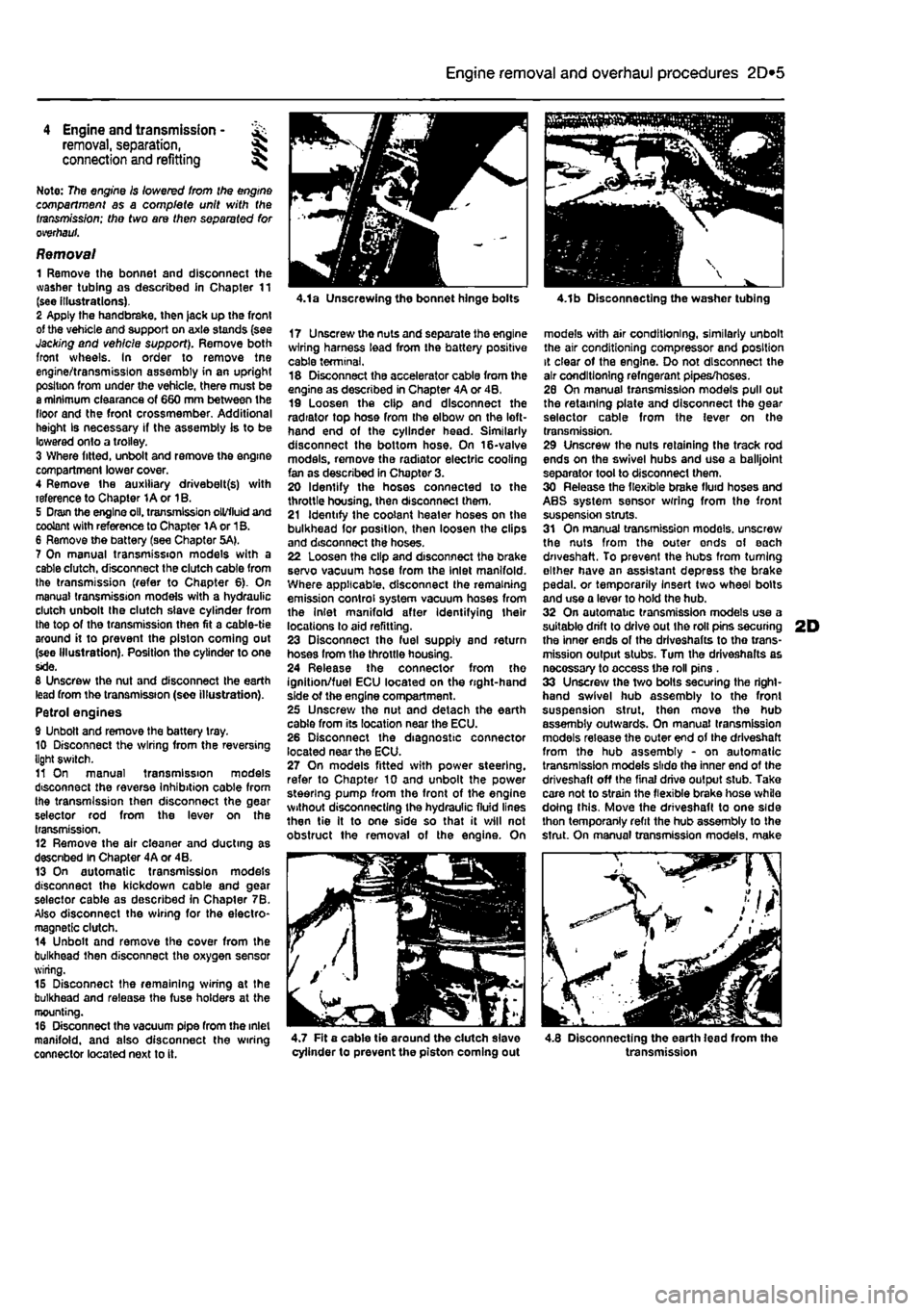
Removal 1 Remove the bonnet and disconnect the washer tubing as described in Chapter 11 (see illustrations). 2 Apply the handbrake, then jack up the front of the vehicle and support on axle stands (see Jacking and vehicle support). Remove both front wheels. In order to remove tne engine/transmission assembly in an upright position from under the vehicle, there must be a minimum clearance of 660 mm between the floor and the front crossmember. Additional height Is necessary if the assembly is to be lowered onto a trolley. 3 Where fitted, unbolt and remove the engine compartment lower cover. 4 Remove the auxiliary drivebelt(s) with reference to Chapter 1A or 1B. 5 Dram the engine oil. transmission oil/fluid and coolant with reference to Chapter 1A or 1B. 6 Remove the battery (see Chapter 5A). 7 On manual transmission models with a cable dutch, disconnect the clutch cable from the transmission (refer to Chapter 6). On manual transmission models with a hydraulic clutch unbolt the clutch slave cylinder from the top of the transmission then fit a cable-tie around it to prevent the piston coming out (see Illustration). Position the cylinder to one side. 8 Unscrew the nut and disconnect the earth lead from the transmission (see illustration). Petrol engines 9 Unbolt and remove the battery tray. 10 Disconnect the wiring from the reversing light switch. 11 On manual transmission models disconnect the reverse Inhibition cable from the transmission then disconnect the gear selector rod from the lever on the transmission. 12 Remove the air cleaner and ducting as descnbed In Chapter 4A or 4B. 13 On automatic transmission models disconnect the kickdown cable and gear selector cable as described in Chapter 7B. Also disconnect the wiring for the electro-magnetic clutch. 14 Unbolt and remove the cover from the bulkhead then disconnect the oxygen sensor wiring. 15 Disconnect the remaining wiring at the bulkhead and release the fuse holders at the mounting. 16 Disconnect the vacuum pipe from the inlet manifold, and also disconnect the wiring connector located next to it.
4.1a Unscrewing the bonnet hinge bolts
17 Unscrewthenutsandseparatetheengine wiring harness lead from the battery positive cable terminal. 18 Disconnect the accelerator cable from the engine as described in Chapter 4A or 4B, 19 Loosen the clip and disconnect the radiator top hose from the elbow on the left-hand end of the cylinder head. Similarly disconnect the bottom hose. On 16-valve models, remove the radiator electric cooling fan as described in Chapter 3. 20 Identify the hoses connected to the throttle housing, then disconnect them. 21 Identify the coolant heater hoses on the bulkhead for position, then loosen the clips and disconnect the hoses. 22 Loosen the clip and disconnect the brake servo vacuum hose from the Inlet manifold. Where applicable, disconnect the remaining emission control system vacuum hoses from the Inlet manifold after Identifying their locations to aid refitting. 23 Disconnect tho fuel supply and return hoses from the throttle housing. 24 Release the connector from the ignition/fuel ECU located on the right-hand side of the engine compartment. 25 Unscrew the nut and detach the earth cable from its location near the ECU. 26 Disconnect the diagnostic connector located near the ECU. 27 On models fitted with power steering, refer to Chapter 10 and unbolt the power steering pump from the front of the engine without disconnecting the hydraulic fluid lines then tie It to one side so that it will not obstruct the removal of the engine. On
4.1b Disconnecting the washer tubing
models with air conditioning, similarly unbolt the air conditioning compressor and position it clear of the engine. Do not disconnect the air conditioning refngerant pipes/hoses. 26 On manual transmission models pull out the retaining plate and disconnect the gear selector cable from the lever on the transmission. 29 Unscrew the nuts retaining the track rod ends on the swivel hubs and use a balljoint separator tool to disconnect them. 30 Release the flexible brake fluid hoses and ABS system sensor wrring from the front suspension struts. 31 On manual transmission models, unscrew the nuts from the outer ends of each driveshaft. To prevent the hubs from turning either have an assistant depress the brake pedal, or temporarily Insert two wheel bolts and use a lever to hold the hub. 32 On automatic transmission models use a suitable drift to drive out Ihe roll pins securing 2D the inner ends of the drlveshafts to tho trans-mission output stubs. Turn the driveshalts as necossary to access the roll pins . 33 Unscrew the two bolts securing the right-hand swivel hub assembly to the front suspension strut, then move the hub assembly outwards. On manual transmission models release the outer end of the driveshaft from the hub assembly - on automatic transmission models slide the inner end of the driveshaft off the final drive output stub. Take care not to strain the flexible brake hose while doing this. Move the driveshaft to one side thon temporanly refit the hub assembly to the strut. On manual transmission models, make
^ - / //
4.7 Fit a cable tie around the dutch slave cylinder to prevent the piston coming out 4.8 Disconnecting the earth lead from the transmission
Page 106 of 225
Apply a smear of clean engine oil to the gudgeon pin. Slide it Into the piston and through the connecting rod small-end. Check that the piston pivots freely on the rod. then secure the gudgeon pin in position with two new circlips. Ensure that each circlip is correctly located In Its groove in the piston.
Refitting and big-end bearing running ciearance check 27 Prior to refitting the piston/connecting rod assemblies, it Is recommended that the big-end bearing running clearance is checked as follows. Big-end bearing running clearance check 28 Clean the backs of the bearing shells, and the bearing locations in both the connecting rod and bearing cap. 29 Press the bearing shells into their locations, ensuring that the tab on each shell engages in the notch In the connecting rod and cap. Take care not to touch any shell's bearing surface with your fingers. If the onginal bearing shells are being used for the check, ensure that they are refitted in their original locations. The clearance can be checked in either of two ways. 30 One method is to refit the big-end bearing cap to Ihe connecting rod, ensuring that they are litted the correct way around, with the bearing shells in place. Wilh the cap retaining bolls correctly tightened, use an internal micrometer or vernier caliper to measure the internal diameter of each assembled pair of bearing shells. If the diameter of each corresponding crankshaft journal is measured and Ihen subtracted from the bearing internal diameter, the result will be the big-end beanng running clearance. 31 The second, and more accurate method is to use a product called Plasligauge. Ensure that the bearing shells are correctly fitted then place a strand of Plastlgauge on each (cleaned) crankpin journal. 32 Refit the (clean) piston/connecting rod assemblies to the crankshaft, and refit the bg-end bearing caps, using the marks made or noted on removal to ensure that they are fitted the correct way around. 33 Tighten the beanng cap bolts taking care not to disturb the Plastlgauge or rotate the connecting rod dunng the tightening sequence. 34 Dismantle the assemblies without rotating the connecting rods. Use the scale pnnted on the Plastigauge envelope to obtain the big-end bearing running clearance. 35 If the clearance is significantly different from that expected, the bearing shells may be Ihe wrong size (or excessively worn. If the original shells are being re-used). Make sure mat no dirt or oil was trapped between Ihe bearing shells and the caps or block when the clearance was measured. If the Plastigauge was wider al one end than at the other, the crankshaft journal may be tapered.
2D*10 Engine removal and overhaul procedures
7.40a The arrow on the piston crown must point towards the timing belt end of the engine (petrol engine) 36 On completion, carefully scrape away all traces of the Plastigauge material from the crankshaft and bearing shells. Use your fingernail, or some other object which is unlikely to score the beanng surfaces.
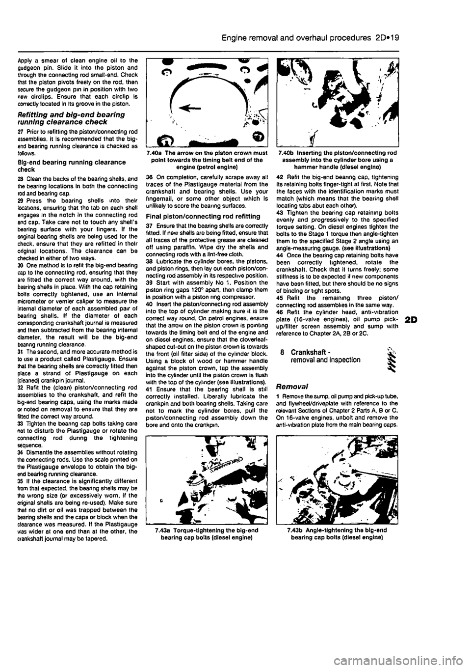
Final piston/connecting rod refitting 37 Ensure that the bearing shells are correctly fitted. If new shells are being fitted, ensure that alt traces of the protective grease are cleaned off using paraffin. Wipe dry the shells and connecting rods with a lint-free cloth. 38 Lubricate the cylinder bores, the pistons, and piston rings, then lay out each piston/con-necting rod assembly in its respective position. 39 Start with assembly No 1. Position the piston ring gaps 120° apart, then clamp them in position with a piston nng compressor. 40 Insert Ihe piston/connecting rod assembly into the top of cylinder making sure it is Ihe correct way round. On petrol engines, ensure that the arrow on the piston crown is pointing towards the timing belt end of the engine and on diesel engines, ensure that the cloverleaf-shaped cut-out on the piston crown is towards the front (oil filter side) of the cylinder block. Using a block of wood or hammer handle against the piston crown, tap the assembly into the cylinder until the piston crown is Hush with the top of the cylinder (sea illustrations). 41 Ensure that the bearing shell is still correctly Installed. Liberally lubricate the crankpin and both bearing shells. Taking care not to mark the cylinder bores, pull the piston/connecting rod assembly down the bore and onto the crankpin.
7.40b Inserting the piston/connecting rod assembly into the cylinder bore using a hammer handle (diesel englno) 42 Refit the big-end beanng cap, tightening Its retaining bolts finger-tight at first, Note that Ihe faces with the identification marks must match (which means that the bearing shell locating tabs abut each other). 43 Tighten the bearing cap retaining bolts evenly and progressively to the specified torque setting. On diesel engines tighten the bolts to the Stage 1 torque then angle-tighten them to the specified Stage 2 angle using an angle-measuring gauge, (see illustrations) 44 Once the bearing cap retaining bolts have been correctly tightened, rotate the crankshaft. Check that il turns freely; some stiffness is to be expected if new components have been fitted, but there should be no signs of binding or tight spots. 45 Refit the remaining three piston/ connecting rod assemblies in the same way. 46 Refit the cylinder head, anti-vibration plate (16-valve engines), oil pump pick-up/filter screen assembly and sump with reference to Chapter 2A, 2B or 2C.
8 Crankshaft -removal and inspection 35
Removal 1 Remove the
sump,
oil pump and pick-up tube, and flywheel/driveplate with reference to the relevant Sections of Chapter 2 Parts A, 8 or C. On 16-valve engines, unbolt and remove the anti-vibration plate from the main bearing caps.
7.43a Torque-tightening the big-end bearing cap bolls (diesel engine) 7.43b Angle-tightening the big-end bearing cap bolts (diesel engine)
Page 114 of 225
3*2 Cooling, heating and ventilation systems
1 General information and precautions
Genera/ Information The engine cooling/cabin heating system is ol pressurised type, comprising a coolant pump driven by the camshaft timing belt (petrol engine models) or auxiliary drlvebelt (diesel engine models), a crossllow radiator, a coolant expansion tank, an electric cooling fan, a thermostat, heater matrix, and all associated hoses and switches. The system functions as follows: Ihe coolant pump circulates cold water around the cylinder block and head passages, and through the Inlet manifold, heater matrix and throttle body to the thermostat housing. When the engine Is cold, the thermostat remains closed and prevents coolant from circulating through the radiator. When the coolant reaches a predetermined temperature, the thermostat opens, and the coolant passes through the top hose to the radiator. As the coolant circulates through the radiator, it is cooled by the in-rush of air when the car is in forward motion. The airllow is supplemented by the action of the electric cooling fan. when necessary, As the temperature of the coolant in the radiator drops, it flows to the bottom of the radiator by convection, and passes out through the bottom hose to the coolant pump - the cycle is then repeatod, When the engine is at normal operating temperature, the coolant expands, and some of It is displaced into the expansion tank. Coolant collects In the tank, and ts returned to Ihe radiator when the system cools. On petrol engine models, the expansion tank is integrated into the side of the radiator. On diesel engine models, and certain petrol engine models with air conditioning, the tank is a separate unit, mounted on the right hand side of the engine compartment. On turbo diesel engine models, the coolant is also passed through a supplementary engine oil cooler, to assist In controlling the engine lubricant temperature. Tho electric cooling fan mounted in front of the radiator is controlled by a thermostatic switch. At a predetermined coolant temperature, the swilch/sensor actuates the tan lo provide additional airflow through the radiator, The switch cuts the electrical supply to the Ion when the coolant temperature has dropped below a preset threshold (see Specifications).
Precautions
A
Warning: Do not attempt to remove the expansion tank pressure cap, or to disturb any part of the cooling system, whlio the engine is hot, as then is a high risk of scalding, tf the expansion tank pressure cap must be removed before the
engine and radiator have fulty cooled (even though this is not recommended?, the pressure in the cooling system must first be relieved. Cover the cap with a thick layer of cloth, to avoid scalding, and slowly unscrew the pressuro cap until a hissing sound Is heard. When the hissing stops, indicating that the pressure has reduced, slowly unscrew the pressure cap until it can be removed; If more hissing sounds are heard, wait until they have stopped before unscrewing the cap completely. At all times, keep your face well away from the pressure cap opening, and protect your hands.
A
Warning: Do not allow antifreeze to come into contact with your skin, or with the painted surfaces of the vehicle. Rinse off spills immediately, with plenty of water. Never leave antifreeze lying around in an open container, or In a puddle In the driveway or on the garage floor. Children and pets are attracted by its sweet smell, but antifreeze can be fatal tf ingested.
A
Warning: If the engine is hot, the electric cooling fan may start rotating even if the engine and ignition are switched off. Be careful to keep your hands, hair, and any loose clothing well clear when working In the engine compartment.
2 Cooling system hoses - f&> disconnection and renewal ^
1 The number, routing and pattern of hoses will vary according to model, but the same basic procedure applies. Before commencing work, make sure that the new hoses are to hand, along wilh new hose clips if needed, it is good practice to renew the hose clips at the same time as the hoses. 2 Drain the cooling system, as described in Chapter 1A or 18, saving the coolant if it is fit for re-use. Apply a little penetrating oil onto the hose clips if they are corroded. 3 Release the hose clips from the hose concerned. Three types of clip are used; worm-drive. spring and 'sardine-can'. The worm-drive clip is released by turning its screw anti-clockwise. The spring clip Is released by squeezing Its tags together with pliers, at the same time working the cbp away from the hose stub. The sardine-can clips are not re-usable, and are best cut off with snips or side cutters. 4 Unclip any wires, cables or other hoses which may be attached to the hose being removed. Make notes for reference when reassembling If necessary. 5 Release the hose from its stubs with a twisting motion. Be careful not to damage the stubs on deltcate components such as the radiator, or thermostat housings. If the hose Is stuck fast, the best course is often to cut it off using a sharp knife, but again be careful not to damage the stubs.
6 Before fitting the new hose, smear the stubs with washing-up liquid or a suitable rubber lubricant to aid fitting. Do not use oil or grease, which may attack the rubber. 7 Fit the hose clips over the ends of the hose, then fit the hose over its stubs. Work the hose Into position. When satisfied, locate and tighten the hose dips. 6 Refill the cooling system as described In Chapter 1A or 1B. Run the engine, and chock that there are no leaks. 9 Recheck the tightness of Ihe hose clips on any new hoses after a few hundred miles. 10 Top-up the coolant level if necessary.
3 Radiator -
removal,
inspection and refitting
Removal Note: If leakage is the reason for removing
the
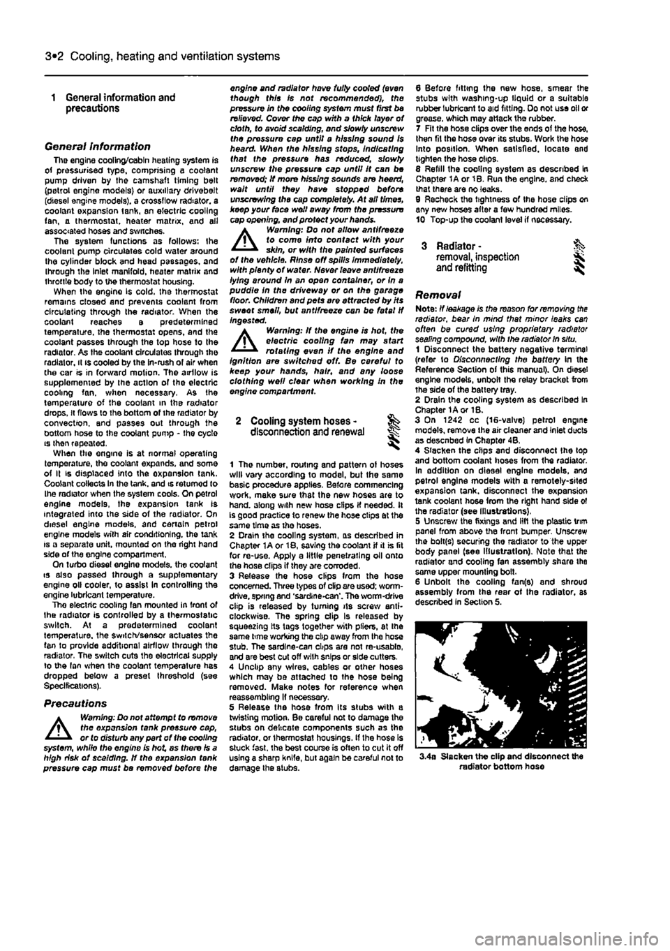
radiator, bear In mind that minor leaks can often be cured using proprietary radiator sealing compound, with the radiator in situ. 1 Disconnect the battery negative terminal (refer to Disconnecting the battery In the Reference Section of this manual). On diesel engine models, unbolt the relay bracket from the side of the battery tray. 2 Drain the cooling system as described In Chapter 1A or 1B. 3 On 1242 cc (16-valve) petrol engine models, remove the air cleaner and Inlet ducts as desenbed In Chapter 4B, 4 Slacken the clips and disconnect Ihe (op and bottom coolant hoses from the radiator. In addition on diesel engine models, and petrol engine models with a remotely-sited expansion tank, disconnect the expansion tank coolant hose from the right hand side ol the radiator (see Illustrations), 5 Unscrew the fixings and lift the plastic trim panel from above the front bumper Unscrew the bolt(s) securing tho radiator to the upper body panel (see Illustration). Note that the radiator and cooling fan assembly share the same upper mounting bolt. 6 Unbolt the cooling fan(e) and shroud assembly from Ihe rear ot the radiator, as described in Section 5.
3.4a Slacken the clip and disconnect the radiator bottom hose
Page 117 of 225
3*2 Cooling, heating and ventilation systems
4 If the motor operates when tested as described, (he fault must lie In the engine wring harness or the temperature sensor. The temperature sensor/switch can be tested as described in Section 6. Any further fault Diagnosis should be referred to a suitably-equipped Fiat dealer - do not attempt to test
Ihe
electronic control unit.
Removal 5 Disconnect the battery negative terminal (refer to D/scon oecf/ng the battery in the Reference Section of this manual). 6 On diesel engine models, unbolt the relay bracket from the side of the battery tray to improve access. On 1242 cc {16-valve) petrol engine models, remove the air cleaner and
inset
ducts as described in Chapter 4B. 1 Disconnect the motor wiring connectorfs). 8 Unbolt the shroud from the rear of the ratiator. then lift out the cooling fan assembly. Refitting 9 Refitting is a reversal of removal
6 Cooling fan switch -testing, removal and refitting ^
Testing 1 The switch is threaded into the lower left
nand
comer of the radiator. 2 The switch can be tested by removing it,
and
checking that the switching action occurs
at
the correct temperature {heat the sensor in a container of water, and monitor the temperature with a thermometer). 3 There should be no continuity between the switch terminals, until Ihe specified cooling fan cut-In temperature Is reached, when continuity (and zero resistance) should exist between the terminals.
Removal 4 Disconnect the battery negative terminal refer to Disconnecting the battery in the Reference Section of this manual). 5 Allow the engine to cool completely, then drain the cooling system as described in Chapter 1Aor 1B. 6 Disconnect the wiring plug from the sensor.
bolts...
7 Carefully unscrew the sensor and. whore applicable, recover the sealing ring. Refitting 8 If the sensor was originally fitted using sealing compound, clean the sensor threads thoroughly, and coat them with fresh sealing compound. 9 If the sensor was originally fitted using a sealing ring, use a new sealing ring on refitting. 10 Refitting is a reversal of removal, but refill the cooling system as described in Chapter 1A or 18. 11 On completion, start the engine and run it until it reaches normal operating temperature. Continue to run the engine until the cooling fan cuts in and out correctly.
7 Coolant pump • & removal, inspection 5 and refitting
Removal
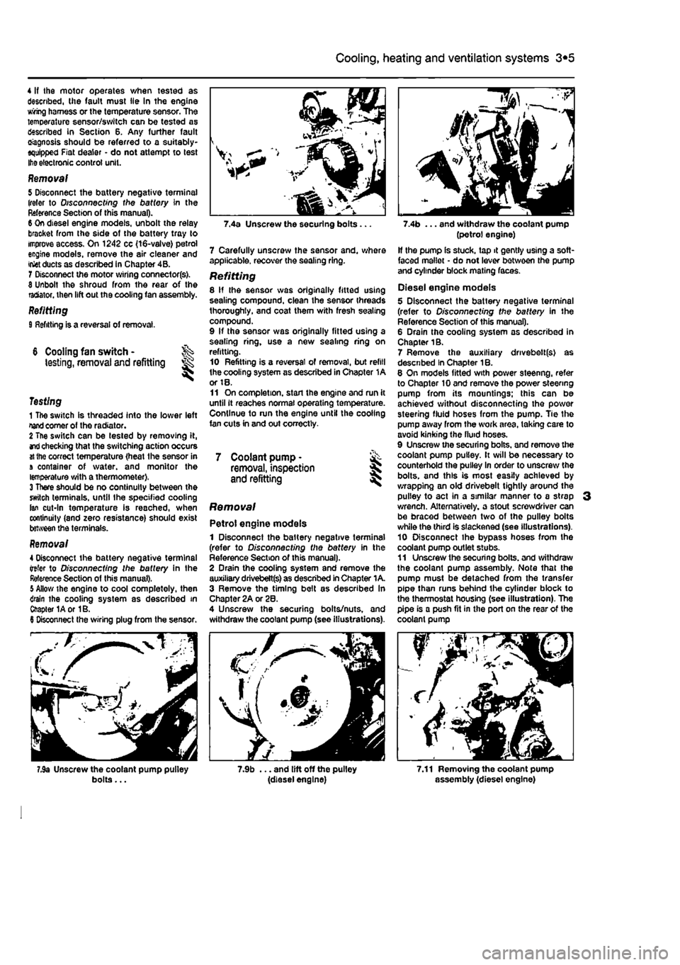
Petrol engine models 1 Disconnect the battery negative terminal (refer to Disconnecting the battery in the Reference Section of this manual). 2 Drain the cooling system and remove the auxiliary drivebett(s) as described In Chapter 1 A. 3 Remove the timing belt as described In Chapter 2A or 28. 4 Unscrew the securing bolts/nuts, and withdraw the coolant pump (see illustrations).
7.9b ... and lift off the pulley (diesel engine)
(petrol engine) If the pump Is stuck, tap it gently using a soft-faced mallet - do not lever between the pump and cylinder block mating faces.
Diesel engine models 5 Disconnect the battery negative terminal (refer to D/s connecting the battery in the Reference Section of this manual). 6 Drain the cooling system as described in Chapter 1B. 7 Remove the auxiliary drivebelt(s) as descnbed In Chapter 1B. 6 On models fitted with power steenng, refer to Chapter 10 and remove the power steering pump from its mountings; this can be achieved without disconnecting the power steering fluid hoses from the pump. Tie the pump away from the work area, taking care to avoid kinking the fluid hoses. 9 Unscrew the securing bolts, and remove the coolant pump pulley. It will be necessary to counterhold the pulley In order to unscrew the bolts, and this is most easily achieved by wrapping an old drivebelt tightly around the pulley to act in a similar manner to a strap 3 wrench. Alternatively, a stout screwdriver can be braced between two of the pulley bolts while the third is slackened (see illustrations). 10 Disconnect ihe bypass hoses from the coolant pump outlet stubs. 11 Unscrew the securing bolts, and withdraw the coolant pump assembly. Note that the pump must be detached from the transfer pipe than runs behind the cylinder block to the thermostat housing (see illustration). The pipe is a push fit in the port on the rear of the coolant pump
7.11 Removing the coolant pump assembly (diesel engine)
Page 118 of 225
3*2 Cooling, heating and ventilation systems
12 If tho pump is stuck, tap It gently using a soft-faced mallet • do not lever between the pump and cylinder block mating faces.
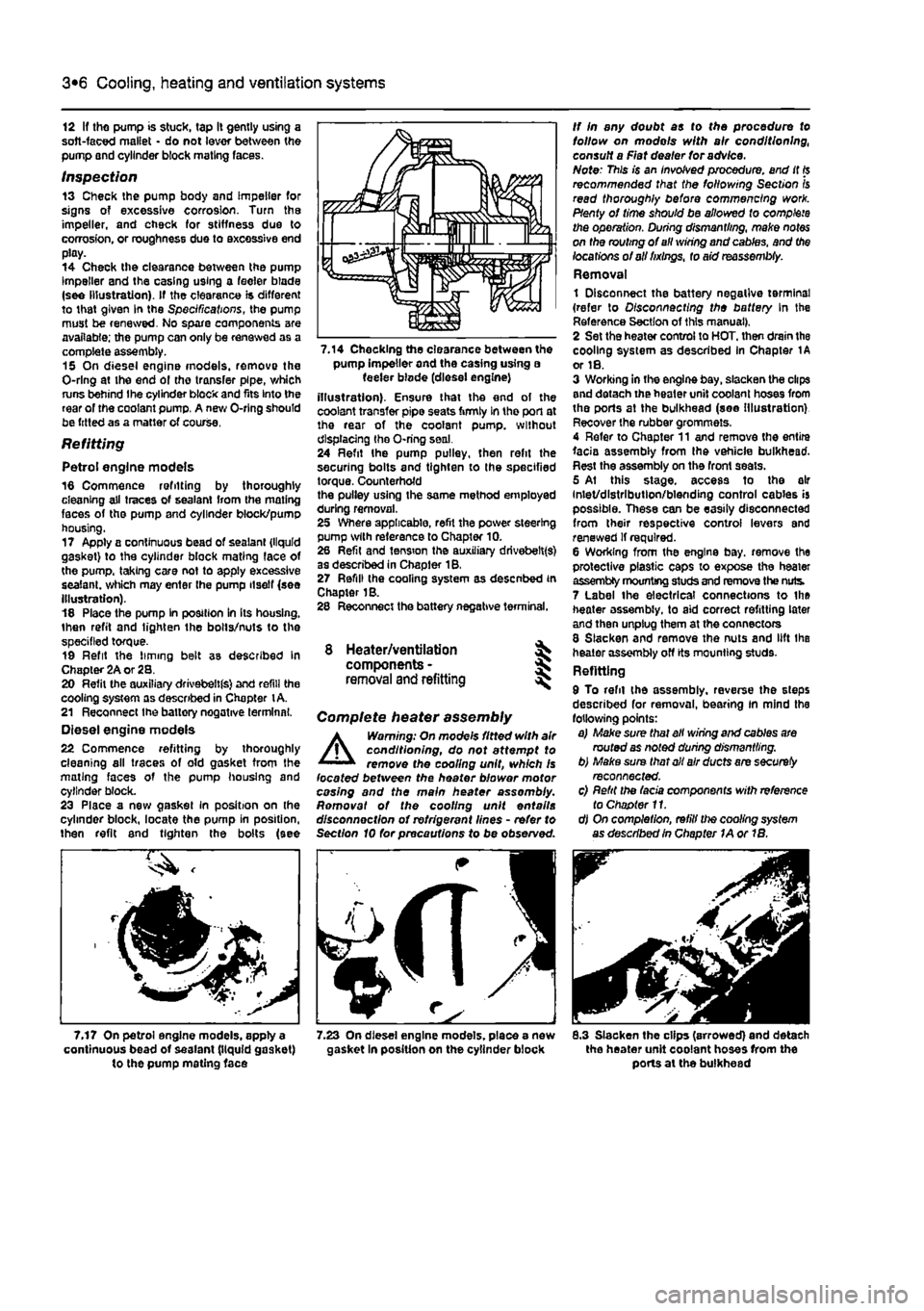
Inspection 13 Check the pump body and impeller for signs of excessive corrosion. Turn the impeller, and check for stiffness due to corrosion, or roughness due to excessive end play. 14 Check the clearance between the pump Impeller and the casing using a feeler blade (see Illustration). If the clearance is different to that given In the Specifications, the pump must be renewed. No spare components are available; the pump can only be renewed as a complete assembly. 15 On diesel engine models, remove the O-rlng at the end ol the transfer pipe, which runs behind Ihe cylinder block and fits Into the rear of the coolant pump. A new O-rlng should be fitted as a matter of course.
Refitting
Petrol engine models 16 Commence refitting by thoroughly cleaning all traces of sealant from the mating faces of the pump and cylinder block/pump housing. 17 Apply a continuous bead of sealant {liquid gasket) to the cylinder block mating face of the pump, taking care not to apply excessive sealant, which may enter the pump itself (see Illustration). 18 Place the pump In position In Its housing, then refit and lighten the bolts/nuts to the specified torque. 19 Refit the liming belt as described In Chapter 2A or 28. 20 Refit the auxiliary drivebeltfs) and refill the cooling system as described in Chapter
t
A. 21 Reconnect Ihe battery negative terminal. Diesel engine models 22 Commence refitting by thoroughly cleaning all traces of old gasket from the mating faces of the pump housing and cylinder block. 23 Place a new gasket in position on (he cylinder block, locate the pump in position, then refit and tighten the bolts (see
7.17 On petrol engine models, apply a continuous bead of sealant (liquid gasket) to the pump mating face
pump Impeller and the casing using a feeler blode (diesel engine) illustration). Ensure that the end of the coolant transfer pipe seats firmly In tho port at the rear of the coolant pump, without displacing the O-ring seal. 24 Refit Ihe pump pulley, then refit the securing bolts and tighten to the specified torque. Counterhofd the pulley using the same method employed during removal. 25 Where applicable, refit the power steering pump with reference to Chapter 10. 26 Refit and tension the auxiliary drivebelt(s) as described in Chapter 18. 27 Refill (he cooling system as desenbed in Chapter 1B. 28 Reconnect the battery negative terminal.
8 Heater/ventilation components - § removal and refitting
Complete heater assembly
A
Warning: On mode's fitted with air conditioning, do not attempt to remove the cooling unit, which Is located between the heater blower motor casing and the main heater assembly. Romovat of the cooling unit entails disconnection of refrigerant lines - refer to Section 10 for precautions to be observed.
rfJS
8.3 Slacken the clips (arrowed) and detach the heater unit coolant hoses from the ports at the bulkhead
Page 121 of 225
4A«1
Chapter 4 Part A:
Fuel system - single-point petrol injection models
Contents
Accelerator cable • removal, refitting and adjustment 4 Air cleaner and inlet system - removal and refitting 2 Air cleaner filter element renewal See Chapter 1A Engine management system components - removal 8nd refitting .. 5 fuel filter renewal See Chapter 1A Fuel injection system - depressurlsatlon 8 Fuel injection system • testing and adjusting 10
Degrees of difficulty
Fuel pump/fuel gauge sender unit - removal and refitting 8 Fuel tank - removal and refitting 7 General information and precautions 1 Idle speed and mixture adjustment See Chapter 1A Inlet air temperature regulator • removal and refitting 3 Inlet manifold - removal and refitting 9 Unleaded petrol - general Information and usage 11
Easy, suitable for Fairty easy, suitable Fairly difficult, Jx suitable for competent ^ OY mechanic ^
DifficUt, suitable tor % Very difficult, ^ novice with Me for begrmer with &
Fairly difficult, Jx suitable for competent ^ OY mechanic ^ experienced DIY > * suitable for expert D(Y JS or professional ^ experience some experience &
Fairly difficult, Jx suitable for competent ^ OY mechanic ^ mechanic > * suitable for expert D(Y JS or professional ^
Specifications
System type Weber-Marelll integrated single-point fuel injection/ignition system
Fuel system data Fuel pump type Electric, Immersed in fuel tank Fuel pump delivery rate 110 litres/hour minimum Regulated fuel pressure 1.0 ± 0.2 bar Crankshaft TDC sensor resistance at 20°C €50 to 720 ohms Injector duration (at idle)
1
£ ms
Recommended fuel Minimum octane rating 95 RON unleaded
Torque wrench settings Nm ibfft Coolant temperature sensor 3 2 Fuel filter collar nut S 4 Fuel tank 28 21 Idle control stepper motor 4 3 Inlet manifold 27 20 Inlet union to filter 31 23 Outlet union to filter 15 11 Throttle body to manifold 7 5 Throttle potentiometer 3 2
Page 122 of 225
4A*2 Fuel system - single-point petrol Injection models
1 General information and precautions
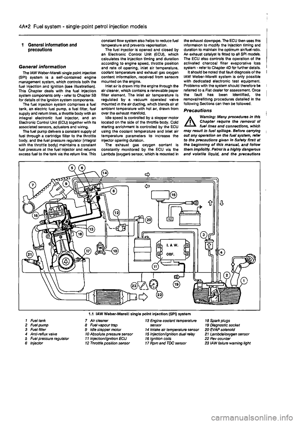
General information The iAW Weber-Marelli single point Injection (SPI) system is a self-contained engine management system, which controls both the fuel Injection and Ignition (see Illustration), This Chapter deals with the fuel Injection system components only - refer to Chapter 5B for details ol the ignition system components. The fuel Injection system comprises a fuel tank, an electric fuel pump, a fuel filter, fuel supply and return lines, a throttle body with an integral electronic fuel Injector, and an Electronic Control Unit (ECU) together with its associated sensors, actuators and wiring. The fuel pump delivers a constant supply of fuel through a cartridge fitter to the throttle body, and the fuel pressure regulator (integral with the throttle body) maintains a constant fuel pressure at the fuel injector and returns excess fuel to the tank via the return line. This
constant flow system also helps to reduce fuel temperature and prevents vaporisation. Tne fuel injeclor Is opened and closed by an Electronic Control Unit (ECU), which calculates the injection timing and duration according to engine speed, throttle position and rate of opening, Inlet air temperature, coolant temperature and exhaust gas oxygen content information, received from sensors mounted on the engine. inlet air is drawn Into the engine through the air cleaner, which contains a renewable paper filter element. The inlet air temperature is regulated by a vacuum operated valve mounted in the air ducting, which blends air at ambient temperature with hot air, drawn from over the exhaust manifold. Idle speed is controlled by a stepper motor located on the side of the throttle body. Cold starling enrichment is controlled by the ECU using the coolant temperature and inlet air temperature parameters to increase the injector opening duration. The exhaust gas oxygen content is constantly monitored by the ECU via the Lambda (oxygen) sensor, which is mounted in
me exhaust downpipe. The ECU then uses this Information to modify the Injection timing and duration to maintain the optimum air/fuel ratio. An exhaust catalyst Is fitted to all SPI models. The ECU also controls the operation of the activated charcoal filter evaporative loss system • refer to Chapter 4D for further details. It should be noted that fault diagnosis of the I IAW Weber-Marelli system is only possible with dedicated electronic test equipment. Problems with the system should therefore be I referred to a Flat dealer for assessment. Once i the fault has been Identified, the I removal/refitting procedures detailed in the following Sections can then be followed.
Precautions |
A
Warning: Many procedures in thH Chapter require the removal ot fuel lines and connections, which may result in fuel spillage. Before carrying | out any operation on Me fuel system, refer to the precautions given In Safety flrstt at the beginning ot this manual, and follow them Implicitly. Petrol Is a highly dangerous and volatile liquid, and the precautions
1.1 IAW Weber-Marelli single point Injection (SPI) system 1 Fuel
tank
2 Fuel pump 3 Fuel filter 4 Anii'reflux valve 5 Fuel pressure regulator 6 Injector
7 Air cleaner 8 Fuel vapour
trap
9 Idle stepper motor
10
Absolute pressure sensor J11njection/ignition ECU 12 Tnrottle position sensor
13 Engine coolant temperature sensor 14 Intake air temperature sensor 15 Inject'onfignitron dual
relay
16 Ignition coils 17 Rpm and TDC sensor
18 Spark plugs 79 Diagnostic socket 20 EVAP solenoid 21 Lambda/oxygen sensor 22 Rev counter 23 IAW failure warning light
Page 123 of 225
4A*2 Fuel system - single-point petrol Injection models
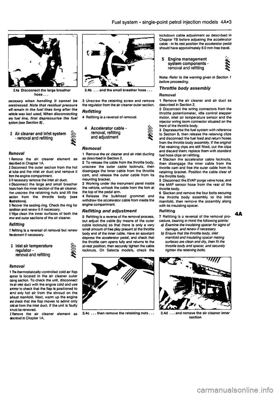
2.4a Disconnect the large breather hose... ziecessary when handling it cannot be mrstressed. Note that residual pressure
wttf
remain in the tuei lines long after the wh/cte was last used, When disconnecting any fuel line, first depressurise the fuel
system
(see Section 8).
2 Air cleaner and intet system • removal and refitting
1
Accelerator cable -removal, refitting and adjustment l
Removal 1 Remove the air cleaner element as described in Chapter 1A. 2 Disconnect the outer section from the hot
air
tube and the inlet air duct and remove it
from
the engine compartment. 3II necessary remove the inlet air duct. 4 Disconnect Ihe large and small breather
roses
from the inner section of the air cleaner, tftsn unscrew the retaining nuts and lift the section from the throttle body (see lustrations).
5
Recover the sealing ring. Check the ring for condition and renew it if necessary.
6
Wipe clean the inner surfaces of both the merand outer sections of the air cleaner. Refitting 7 Refitting Is a reversal ol removal but renew
tie
element
H
necessary.
3 Inlet air temperature regulator -removal and refitting
Removal t
The
thermostatically-controlled cold air flap cpener is located in the air cleaner outer ttsrig section. To check the unit, disconnect
ire air
inlet duct with the engine cold and use imrrorto check that the flap Is positioned to aJmit only hot air from the shroud on the utaust manifold. Next, warm up the engine
and
check that the flap moves to admit only sett air from the inlet duct. If the unit is faulty fl must be renewed.
2
Remove the air cleaner element as •senbod in Chapter
1
A.
kickdown cable adjustment as described in Chapter 7B before adjusting the accelerator cable • in its rest position the accelerator pedal should have approximately 8.0 mm free travel.
5 Engine management system components -removal and refitting I
2.4b ... and the small breather hose ...
3 Unscrew the retaining screw and remove the regulator from the air cleaner outer section.
Refitting 4 Refitting is a reversal of removal.
Removal 1 Remove the air cleaner and air inlet ducting as desenbed in Section 2. 2 To release the cable from the throttle body, unscrew the outer cable locknuts, then disengage the inner cable from the throttle cam, and release the outer cable from its mounting bracket. 3 Working under the instrument panel inside the vehicle, unhook the cable from the fork at the top of the pedal arm. 4 Release the bulkhead grommet and withdraw the accelerator cable from Inside the engine compartment.
Refitting and adjustment 5 Refitting is a reverse of the removal process, but adjust the cable (by means of the outer cable locknuts) so that there is only a very small amount of free play present at the throttle body end of the inner cable. Have an assistant depress the accelerator pedal, and check that the throttle cam opens fully and returns to the at-rest position, then secureJy tighten the cable locknuts. On Selecta models, check the
Note: Refer to the warning given in Section 1 before proceeding. Throttle body assembly
Removal 1 Remove the air cleaner and air duct as desenbed in Section 2. 2 Disconnect the wiring connectors from the throttle potentiometer, idle control stepper motor, inlet air temperature sensor and the injector wiring loom connector situated on the front of the throttle body. 3 Depressurise the fuel system with reference to Section 8, then release the retaining clips and disconnect the fuel feed and return hoses from the throttle body assembly, if the original Fiat retaining clips are still fitted, cut the clips and discard them; replace them with standard luel hose clips on refitting. 4 Slacken the accelerator cable locknuts, then disengage the inner cable from the throttle cam and froe tho outer cable from its retaining bracket. Position the cable clear of the throttle body. 5 Disconnect the EVAP purge valve hose, and the MAP sensor hose from the rear of the throttle body. 6 Slacken and remove the four bolts securing the throttle body assembly to tho Inlet manifold, then remove the assembly along with its insulating spacer. Refitting 7 Refitting is a reversal of the removal pro-cedure, bearing in mind the following points: a) Examine the insulating spacer for signs of damage, and renew //necessary, b) Ensure that the throttle body, inlet manifold and insulating spacer ma ting surfaces are clean and dry, then fit the throttle body and spacer, and securely tighten the retaining bolts.
2.4c ... then remove the retaining nuts. 2.4d ... and remove the air cleaner inner section