Chapter 12 FIAT PUNTO 1999 176 / 1.G Workshop Manual
[x] Cancel search | Manufacturer: FIAT, Model Year: 1999, Model line: PUNTO, Model: FIAT PUNTO 1999 176 / 1.GPages: 225, PDF Size: 18.54 MB
Page 7 of 225
o.6 Roadside repairs
The following pages are Intended to help In dealing with common roadside emergencies and breakdowns. You will find more detailed fault finding information at the back of the manual, and repair Information In the main chapters.
If your car won't start
and the starter motor
doesn't turn
If your car won't start
even though the starter
motor turns as normal
tf it's a model with automatic transmission, make sure the selector is in P or N. Open the bonnet and make sure that the battery terminals are clean and tight. Switch on the headlights and try to start the engine. If the headlights go very dim when you're trying to start, the battery is probably flat. Get out of trouble by Jump starting (see next page) using a friend's car.
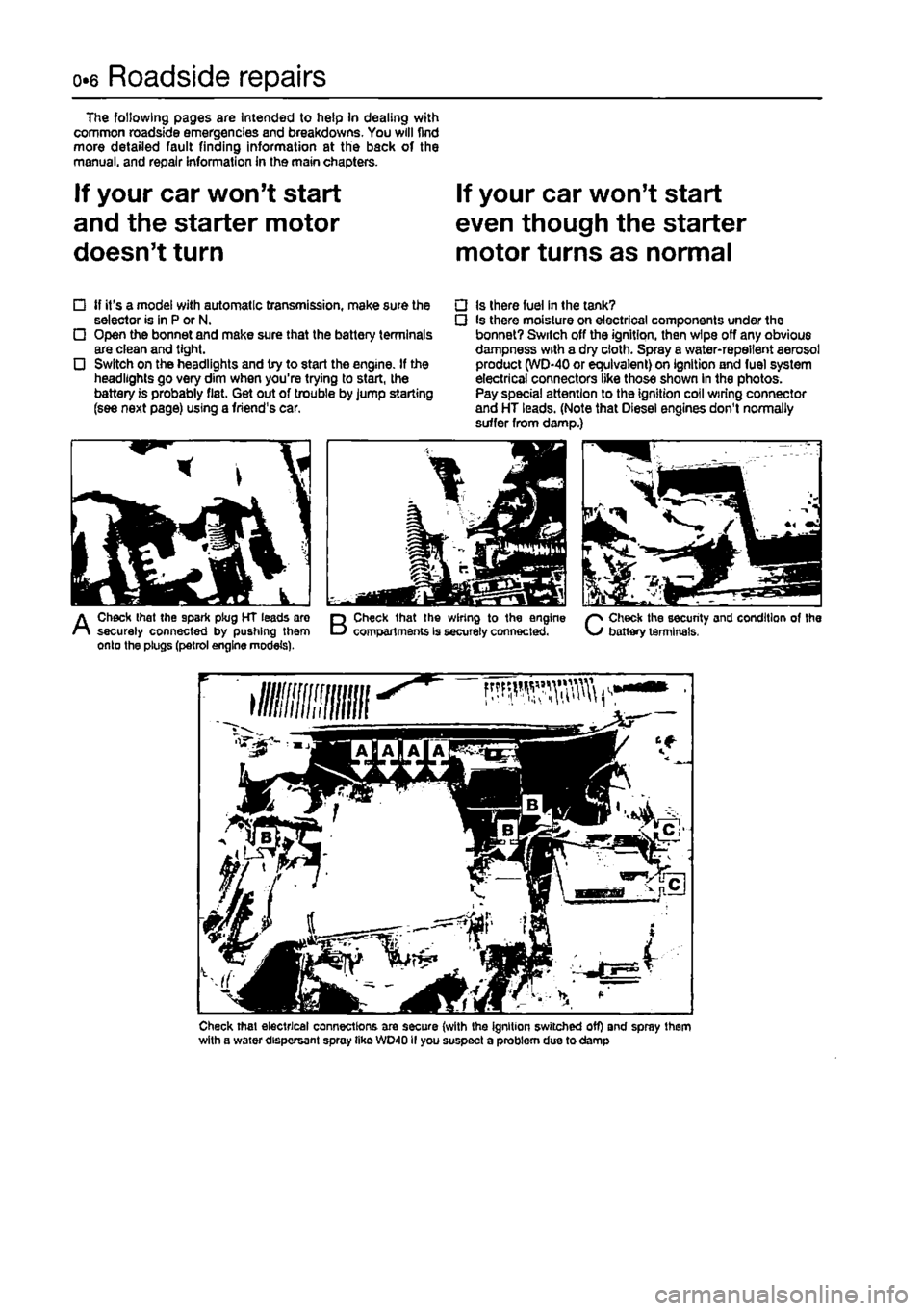
• Is there fuel In the tank? • Is there moisture on electrical components under the bonnet? Switch off the ignition, then wipe off any obvious dampness with a dry cloth. Spray a water-repellent aerosol product (WD-40 or equivalent) on ignition and fuel system electrical connectors like those shown in the photos. Pay special attention to the ignition coil wiring connector and HT leads. (Note that Diesel engines don't normally suffer from damp.)
A
Check that the spark plug HT leads are securely connected by pushing them onto the plugs (petrol engine models).
B
Check that the wiring to the engine compartments is securely connected.
C
Check the security and condition of the battery terminals,
Check that electrical connections are secure (with the ignition switched off) and spray them with a water dispersant spray tike WD40II you suspect a problem due to damp
Page 10 of 225
Roadside repairs 0.9
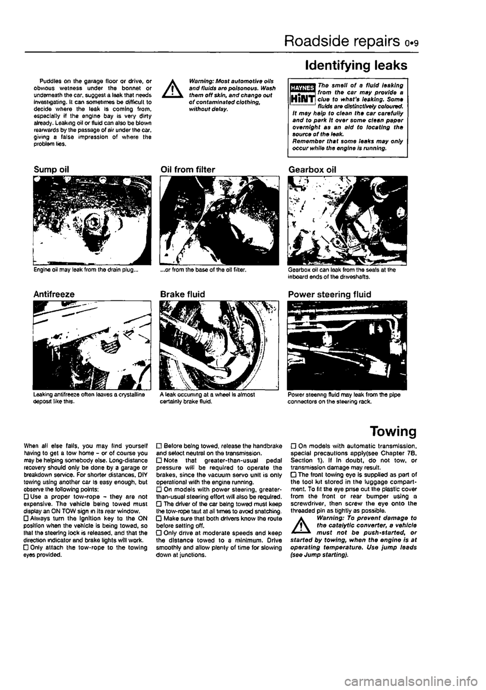
Puddles on the garage floor or drive, or obvious wetness under the bonnet or underneath the car, suggest a leak that needs Investigating. It can sometimes be difficult to decide where the leak is coming from, especially if the engine bay is very dirty already. Leaking oil or fluid can also be blown rearwards by the passage of air under the car, giving a false impression of where the problem lies.
A
Warning: Most automotive oils and fluids aro poisonous. Wash them off skin, and change out of contaminated clothing, without delay.
Identifying leaks
The smell of 0 fluid leaking from the car may provide a clue to what's leaking. Some fluids are distinctively coloured. It may help to clean the car carefully and to park It over some clean paper overnight as an aid to locating the source of the leak. Remember that some leaks may only occur while the engine is running.
Sump oil
Engine oil may leak from the drain plug...
Antifreeze
Leaking antifreeze often leaves a crystalline oeposit like this.
Oil from filter
A leak occurring at a wheel Is almost certainly brake fluid.
Gearbox oil
Gearbox oil can leak from the seals at the inboard ends of the drivoshafts.
Power steering fluid
Power steering fluid may leak from the pipe connectors on the steering rack.
When ail else falls, you may llnd yourself having to get a tow home - or of course you may be helping somebody else. Long-distance recovery should only be done by a garage or breakdown service. For shorter distances. OIY towing using another car is easy enough, but observe the following points: • Use a proper tow-rope - they are not expensive. The vehicle being towed must display an ON TOW sign in its rear window. • Always turn the Ignition key to the ON position when the vehicle is being towed, so that the steering lock is released, and that the direction indicator and brake lights will work. • Only attach the tow-rope to the towing eyes provided.
• Before being towed, release the handbrake and select neutral on the transmission. • Note that greater-then-usual pedal pressure will be required to operate the brakes, since the vacuum servo unit is only operational with the engine running. • On models with power steering, greater-than-usual steering effort will also be required. • The driver of the car being towed must keep the tow-rope taut at all times to avoid snatching. • Make sure that both drivers know the route before setting off. • Only dnve at moderate speeds and keep the distance towed to a minimum. Drive smoothly and allow plenty of time for slowing down at junctions.
Towing
• On models with automatic transmission, special precautions apply(see Chapter 7B. Section 1). If In doubt, do not tow, or transmission damage may result. • The front towing eye is supplied as part of the tool kit stored in the luggage compart-ment. To fit the eye pnse out the plastic cover from the front or rear bumper using a screwdriver, then screw the eye onto the threaded pin as tightly as possible.
A
Warning: To prevent damage to the catalytic converter, e vehicle must not be push'started, or started by towing, when the engine is at operating temperature. Use jump leads (see Jump starting).
Page 14 of 225
Weekly checks 0.13
Brake fluid level
A
Warning: • Brake fluid can harm your eyes and damage painted surfaces, so use extreme caution when handling and pouting it.
• Do not use fluid that has been standing open for so mo time, as It absorbs moisture from the air, which can cause a dangerous loss of braking effectiveness.
Mpmna * Make sure that your car Is I on level ground. HiNTi * Th* ffftt 'eve/ In the reservoir will drop slightly as
I
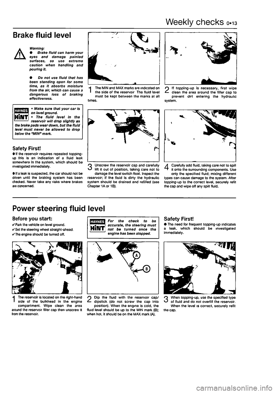
The MIN and MAX marks are indicated on the side of Ihe reservoir The fluid level must be kept between the marks at all times.
2
11 topping-up is necessary, first wipe clean the area around the filler cap to prevent dirt entering the hydraulic system.
the brake pads wear down, but the fluid level must never be allowed to drop below the "MIN" mark.
Safety First! • If the reservoir requires repeated topping* up this is an indication of a fluid leak somev/here In the system, which should be investigated immediately.
• If a leak is suspected, the car should not be driven until the braking system has been checked. Never take any risks where brakes are concerned.
Unscrew the reservoir cap and carefully lift it out of position, taking care not to damage the level switch float. Inspect the reservoir: if the fluid Is dirty Ihe hydraulic system should be drained and refilled (see Chapter 1A or 1B).
4
Carefully add fluid, taking care not to spill it onto the surrounding components, Use only the specified fluid; mixing different types can cause damage to the system. After topping-up to the correct level, secureiy refit the cap and wipe off any spilt fluid.
Power steering fluid level
Before you start: •Park the vehicle on level ground. • Set the steering wheel straight-ahead. •
The
engine should be turned off.
I
The reservoir is located on the right-hand side of the bulkhead in the engine compartment. Wipe clean the area around the reservoir filler cap then unscrew It from the reservoir.
For the check to be accurate, the steering must HlHT; not be turned once the engine has been stopped.
2
Dip the fluid with the reservoir cap/ dipstick (do not screw the cap into position). When the engine is cold, the fluid level should be up to Ihe MIN mark (B): when hot. it should be on the MAX mark (A).
Safety First! • The need for frequent topping-up indicates a leak, which should be investigated immediately.
3
When topping-up, use the specified type of lluid and do noi overfill the reservoir. When the level is correct, securely refit the cap.
Page 17 of 225
o«i6 Weekly checks
Battery
Caution: Before carrying out any work on the vehicle battery, read the precautions given In "Safety first" at the start of this manual. • Make sure thai the battery tray is in good condition, and that the clamp Is tight. Coirosion on the tray, retaining clomp and the battery itself can be removed with a solution of water and baking soda, Thoroughly rinse all cleaned areas with water. Any metal parts damaged by corrosion should be covered with a zinc-based primer, then painted. • Periodically (approximately every three months), check the charge condition of the battery as described In Chapter SA. • If the battery Is flat, and you need to jump start your vehicle, see Roadside Repalrz.
Battery corrosion can be kept to a minimum by applying o layer of petroleum Jelly to the clamps and terminals after they are reconnected
fin %
I
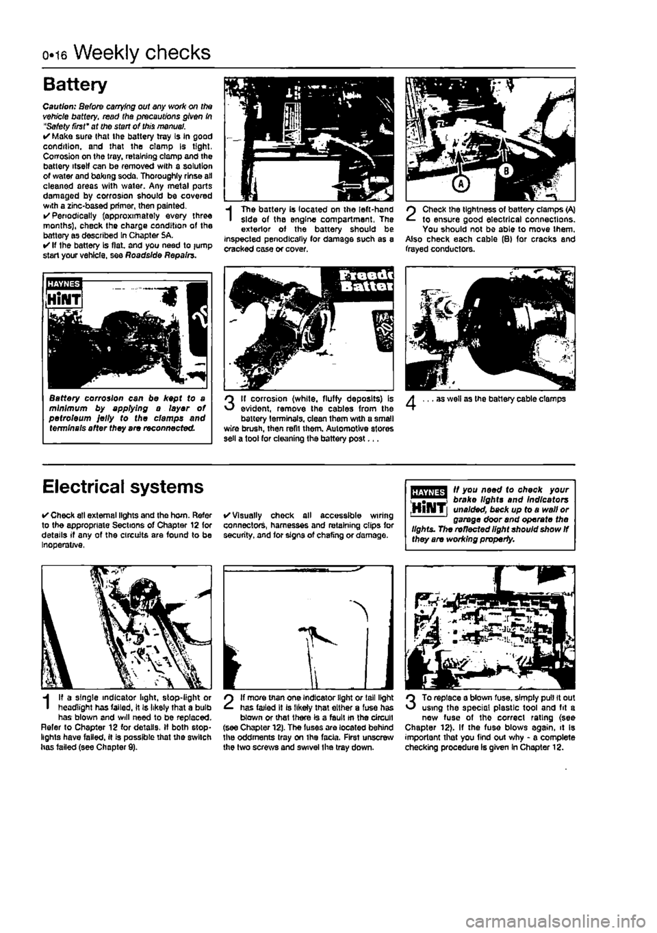
The battery is located on the left-hand side of the engine compartment, The exterior of the battery should be inspected penodlcaily for damage such as a cracked case or cover.
2
Check the tightness of battery clamps (A) to ensure good electrical connections. You should not be able to move them. Also check each cable (B) for cracks and frayed conductors.
3
If corrosion (while, fluffy deposits) is evident, remove the cables from the battery terminals, clean them with a small wire brush, then refit them. Automotive stores sell a tool for cleaning the battery post...
as well as the battery cable clamps
Electrical systems
• Check all external lights and the horn. Refer to the appropriate Sections of Chapter 12 for details if any of the circuits are found to be Inoperative,
• Visually chock all accessible wiring connectors, harnesses and retaining clips for security, and for signs of chafing or damage.
fffjffflg^ " y°u A**^ check your "T™*! broke lights and Indicators ,HllMT[ unaided, back up to a wall or garage door and operate the lights. The reflected light shouid show
If
they are working property.
I
I? a single indicator light, stop-light or headlight has failed, it Is likely that a bulb has blown and will need to be replaced. Refer to Chapter 12 for details. If both stop-lights have failed, it is passible that the switch has failed (see Chapter 9).
2
If more than one Indicator light or tail light has failed It is likely that either a fuse has blown or that there is a fault tn the circuit (see Chapter 12). The fuses are located behind the oddments tray on ihe facia. First unscrew the two screws and swivel Ihe tray down.
3
To replace a blown fuse, simply pull it out using the special plastic tool and fit a new fuse of tho correct rating (see Chapter 12). If the fuse blows again, it is importont that you find out why - a complete checking procedure Is given in Chapter 12.
Page 20 of 225
1A»1
Chapter
1
Part A:
Routine maintenance & servicing - petrol models
Contents
Air
filter renewal 18 Automatic transmission filter and fluid change 2B Auxiliary dr
and filter renewal 3 Evaporative loss system check 27 Exhaust system check 8 From brake pad check 5 Fuel filter renewal 17 Headlight beam adjustment 23 Hinge and lock lubrication 22
Hose and fluid leak check 7 Idle speed and CO content check and adjustment .11 Ignition system check 20 Introduction 1 Lambda/oxygen sensor check 25 Manifold mounting check 16 Manual transmission oil level check 26 Manual transmission oil renewal .32 Pollen filter renewal 10 Rear brake shoe check 29 Regular maintenance 2 Road test 24 Spark plug renewal 19 Steering and suspension check 12 Timing belt renewal 30 Underbody sealant check 6 Valve clearance check and adjustment 15
Degrees of difficulty
Easy, suitable for ^ novice with little experience ^
Fairty easy, suitable for beginner with ^ some experience
FaMy difficult, ^ sitable for competent jj^ DIY mechanic ^
Difficult, suitable for experienced DIY aJ mechanic ^
Very difficult, ^ suitable for expert DIY or professional ^
expert22 fl/ia http://rutracker.org
Page 21 of 225
ia.2 Servicing specifications - petrol models
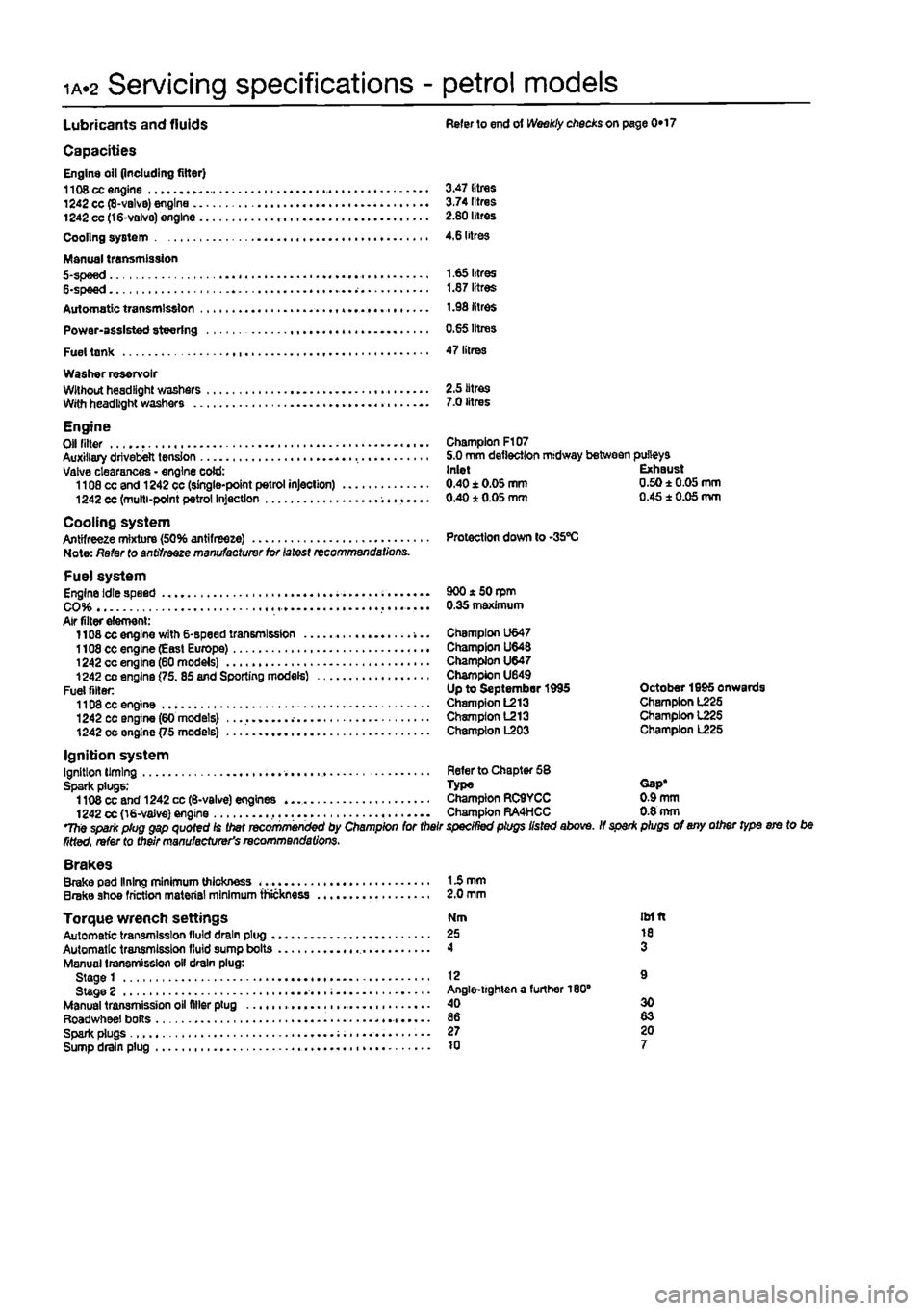
Lubricants and fluids Refer to end ot Weekly checks on page 0*17
Capacities Engine oil (including filter) 1108 cc engine 3.47 litres 1242 cc (8-valvB) engine 3.74 litres 1242 cc (16-valve) engine 2.80 litres Cooling system 4,6 litres
Manual transmission 5-spee d 1.65 litres 6-spee d 1.87 litres Automatic transmission 1.98 litres Power-assisted steering 0.65 Irtres Fuel tank 47 litres Washer reservoir Wllhouthesdllghl washers 2.5 litres With headlight washers 7.0 litres
Engine Olf niter - Champion F107 Auxiliary drivebelt tension 5.0 mm deflection midway between pulleys Valve clearances - engine cold: Inlet Exhaust 1108 cc and 1242 cc (single-point petrol injection) 0.40±0.05mm 0.50±0.05mm 1242 cc (multi-point petrol Injection 0.40 1 0.05 mm 0.45 1 0.05 mm
Cooling system Antifreeze mixture (50% antifreeze) Protection down to -35"C Note: Refer to antifreeze manufacturer for latest recommendations.
Fuel system Engine idle speed . 900 * 50 rpm CO 0.35 maximum Air filter element: 1108 cc engine with 6-speed transmission -... Champion U647 1108 cc engine (Easl Europe) Champion U648 1242 cc engine (60 models) Champion U647 1242
CO
engine (75.85 and Sporting models) Champion U649 Fuel filler: Up to September 1995 October 1995 onwards 1108 cc engine Champion L213 Champion L225 1242 cc engine (60 models) Champion L213 Champion 1225 1242 cc engine {75 models) Champion L203 Champion L225
Ignition system Ignition liming Refer to Chapter 58 Spark plugs: Type Gap* 1108 cc and 1242 cc (6-valve) engines Champion RC9YCC 0.9 mm 1242 cc (16-valve) engine ,... Champion RA4HCC 0.8 mm The spark plug gap quoted Is Diet recommenced by Champion for their specined plugs listed above. If spar* plugs of any other type ere to be fitted, refer to their manufacturer's recommendations. Brakes Brake pad lining minimum thickness 15 mm Brake shoe friction material minimum thickness 2.0 mm
Torque wrench settings Nm itrfft Automatic transmission lluld drain plug 25 10 Automatic transmission fluid sump bolts 4 3 Manual transmission oil drain plug: Stage 1 12 9 Stage 2 Angle-lighten a further 180" Manual transmission oil filler plug 40 30 Roadwheel bolts 86 83 Spark plugs 27 20 Sump drain plug 10 7
Page 25 of 225
ia«6 Component location - petrol models
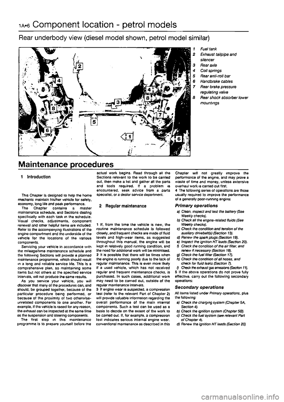
Rear underbody view (diesel model shown, petrol model similar)
1 Fuel
tank
2
Exhaust
tailpipe
and
silencer 3
Rear axle
4 Coll
springs
5
Rear
anti-mil
bar
6
Handbrake cables
T
Rear brake pressure
regulating
valve
S
Rear
shock absorber lower mountings
Maintenance procedures
1 Introduction
This Chapter is designed to help the home mechanic maintain his/her vehicle (or safety, eoonomy, long life and peak performance. The Chapter contains a master maintenance schedule, and Sections dealing specifically with each task in the schedule. Visual checks. ad}ustments, component renewal and other helpful Items are included. Refer to the accompanying Illustrations of the engine compartment and tho underside of the vehicle for the locations of the various components. Servicing your vehicle in accordance with ihe mlleaget/time maintenance schedule and the following Sections will provide a planned maintenance programme, which should result m a long and reliable service life. This Is a comprehensive plan, so maintaining some Items but not others at the specified service Intervals, will not produce the same results. As you service your vehicle, you will discover that many of the procedures can, and should, be grouped together, because of the particular procedure being performed, or because of the proximity of two otherwise-unrelated components to one another. For example, if the vehicle Is raised for any reason, the exhaust can be inspected at the same time as the suspension and steering components. The first step in this maintenance programme is to prepare yoursell before tne
actual work begins. Read through all the Sections relevant to the work to be carried out, then make a list and gather all the parts and tools required. If a problem is encountered, seek advice from a parts specialist, or a dealer service department.
2 Regular maintenance
1 If. from the time the vehicle is new, the routine maintenance schedule is followed closely, and frequent checks are made of fluid levels and high-wear items, as suggested throughout this manual, the engine will be kept in relatively good running condition, and the need for additional work will be minimised. 2 II is possible that there will be times when the engine rs running poorly due to the lack of regular maintenance. This is even more likely If a used vehicle, which has not received regular and frequent maintenance checks, is purchased. In such cases, additional work may need to be carried out. outside of the regular maintenance intervals. 3 If engine wear is suspected, a compression test (refer to the relevant Part of Chapter 2) will provide valuable information regarding the overall performance of the main internal components. Such a test can be used as a basis to decide on the extent of the work to bo carried out. II, for example, a compression test indicates serious internal engine wear, conventional maintenance as described in this
Chapter will not greatly improve the performance of the engine, and may prove a waste of time and money, unless extensive overhaul work is carried out first. 4 The following series of operations are those usually required to improve the performance of a generally poor-running engine:
Primary operations a) Cloan, inspect and test the battery
(See
Weekly checks), b) Check alt the engine-related fluids (See Weekly checks). c) Check the condition and tension of the auxiliary drivebeft($) (Section 13). d) Renew the spark plugs (Section 19). e) Inspect the ignition HT leads (Section 20). 0 Check the condition of the air filter, and renew if necessary (Section 18). g) Check the fuel filter (Section 17). h) Check tho condition of ell hoses, and check for fluid leaks (Sect/on 7). i) Check theexhaust
gas emissions (Section 11).
5 If the above operations do not prove fully effective, carry out the following secondary operations;
Secondary operations All items listed under Primary operations, plus the following; e) Check the charging system (Chapter 5K Section 4). b) Check the ignition system (Chapter 58). c) Check tho fuel system (see relevant Part of Chapter
4).
d) Renew the ignition HT leads (Section 20)
Page 26 of 225
Maintenance procedures - petrol models ia./
Every 5000 miles (7500 km) or 6 months
3 Engine oil and filter renewal Ja*
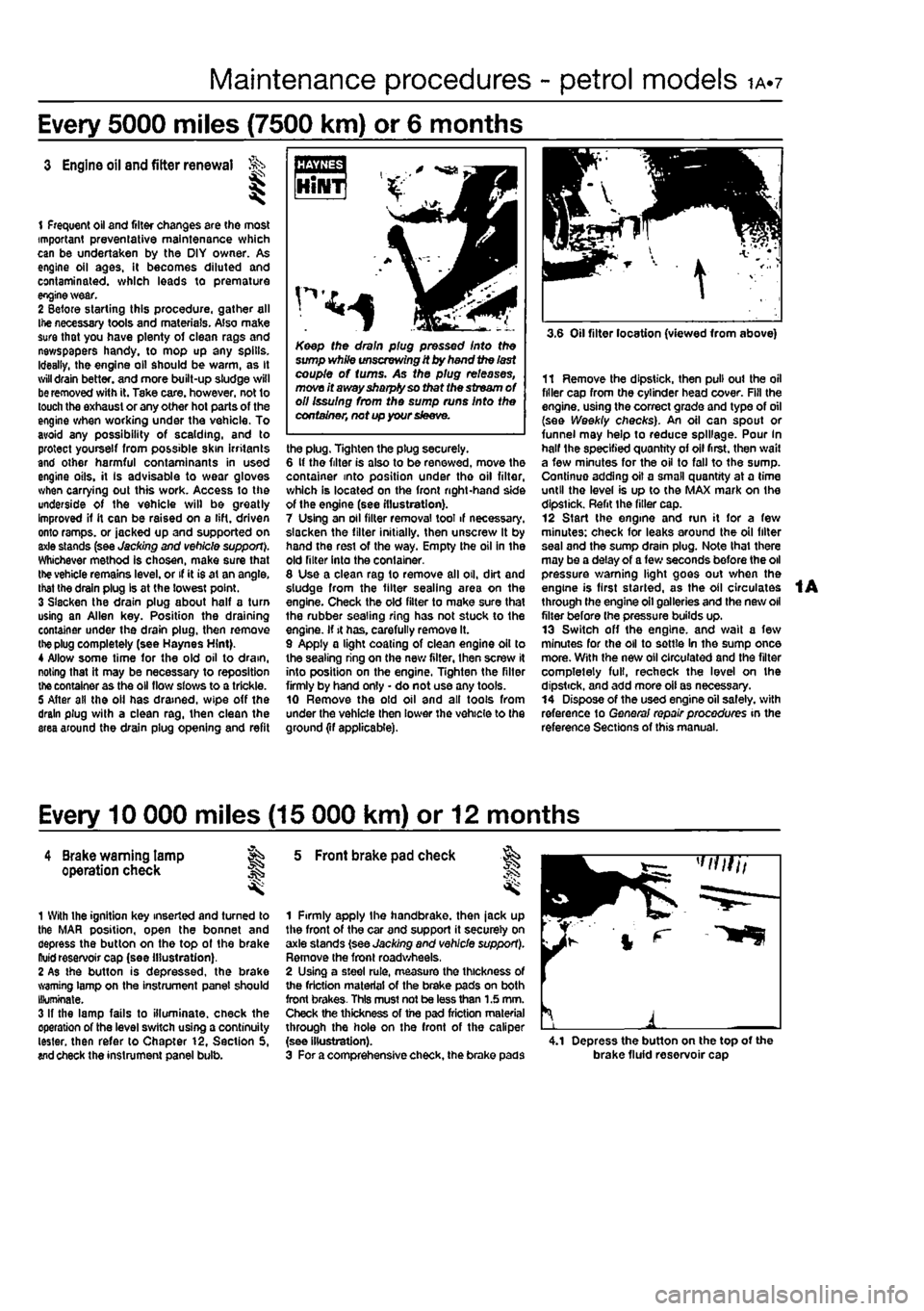
1 Frequent oil and filter changes are the most important preventative maintenance which can be undertaken by the DIY owner. As engine oil ages, it becomes diluted and contaminated, which leads to premature engine wear. 2 Before starting this procedure, gather all Ihe necessary tools and materials. Also make sure that you have plenty of clean rags and newspapers handy, to mop up any spills. Ideally, the engine oil should be warm, as It
will
drain better, and more built-up sludge will
be
removed with it. Tske care, however, not to touch the exhaust or any other hot parts of the engine when working under the vehicle. To avoid any possibility of scalding, and to protect yourself from possible skin irritants end other harmful contaminants in used engine oils, it Is advisable to wear gloves when carrying out this work. Access to the underside of the vehicle will be greatly Improved if it can be raised on a lift, driven onto ramps, or jacked up and supported on axle stands (see Jacking and vehicle support). Whichever method is chosen, make sure that
the
vehicle remains level, or if it is at an angle, that the drain plug Is at the lowest point. 3 Slacken the drain plug about half a turn using an Allen key. Position the draining container under the drain plug, then remove
the plug
completely (see Haynes Hint). 4 Allow some time for the old oil to dram, noting that it may be necessary to reposition
the
container as the oil flow slows to a trickle. 5 After all the oil has drained, wipe off the drain plug with a clean rag, then clean the area around the drain plug opening and refit
(MB
HiNT '
Keep the drain plug pressed Into the sump white unscrewing it by hand the last couple of turns. As the plug releases, move it away sharply so that the stream
of
oil Issuing from the sump runs into the container, net up your sleeve.
the plug. Tighten the plug securely. 6 It the filter is also to be renewed, move the container into position under tho oil filter, which is located on the front right-hand side of the engine (see illustration). 7 Using an oil filter removal tool if necessary, slacken the filter initially, then unscrew It by hand the rest of the way. Empty the oil in the old filter into the container. 8 Use a clean rag to remove all oil, dirt and sludge from the filter sealing area on the engine. Check the old filter to make sure that the rubber sealing ring has not stuck to the engine. If it has. carefully remove It. 9 Apply a light coating of clean engine oil to the sealing ring on the new filter, then screw it into position on the engine. Tighten the filter firmly by hand only • do not use any tools. 10 Remove the old oil and all tools from under the vehicle then lower the vehicle to the ground (if applicable).
3.6 Oil filter location (viewed from above)
11 Remove the dipstick, then pull out the oil filler cap from the cylinder head cover. Fill the engine, using the correct grade and type of oil (see Weekly checks). An oil can spout or funnel may help to reduce spillage. Pour In half the specified quantity of oil first, then wail a few minutes for the oil to fall to the sump. Continue adding oil a small quantity at a time until the level is up to the MAX mark on the dipstick. Refit the filler cap. 12 Start the engine and run it for a few minutes: check for leaks around the oil filter seal and the sump drain plug. Note that there may be a delay of a few seconds before the oil pressure warning light goes out when the engine is first started, as the oil circulates through the engine oil galleries and the new oil filter before (he pressure builds up. 13 Switch off the engine, and wait a few minutes for the oil to settle In the sump once more. With the new oil circulated and the filter completely full, recheck the level on the dipstick, and add more oil as necessary. 14 Dispose of the used engine oil safely, with reference to General repair procedures in the reference Sections of this manual.
Every 10 000 miles (15 000 km) or 12 months
4 Brake warning lamp ag operation check J§
1 With the ignition key inserted and turned to the MAR position, open the bonnet and depress the button on the top of the brake ftuid reservoir cap (see illustration). 2 As the button is depressed, the brake warning lamp on the instrument panel should Illuminate. 3 If the lamp fails to illuminate, check the operation of the level switch using a continuity tester, then refer to Chapter 12, Section 5, wd check the instrument panel bulb.
5 Front brake pad check
1 Firmly apply the handbrake, then jack up the front of the car and support it securely on axle stands (see Jacking and vehicle support). Remove the front roadwheels, 2 Using a steel rule, measure the thickness of the friction material of the brake pads on both front brakes- This must not be less than 1.5 mm. Check the thickness of the pad friction material through the hole on the front of the caliper (see illustration). 3 For a comprehensive check, the brake pads 4.1 Depress the button on the top of the brake fluid reservoir cap
Page 27 of 225
ia«8 Every 10 000 miles - petrol models
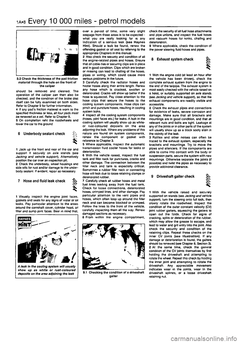
5.2 Check the thickness of the pad friction material through the hole on the front of the caliper should be removed and cleaned. The operation of the caliper can then
bIbo
be checked, and the condition of the brake disc itself can be fully examined on both sides. Refer to Chapter 9 for further Information. 4 If any pad's friction material is worn to the specified thickness or less, all four psds must tie renewed as a set. Refer to Chapter 9. 5 On completion refit the roadwheels and lower the car to the ground
6 Underbody sealant check
I
1 Jack up the front and rear of the car and support It securely on axle stands (see Jacking and vehicle support). Alternatively position the car over an inspection pit. 2 Check the underbody. wheel housings and side sills for rust and/or damage to the under-body sealant. If evident, repair as necessary.
7 Hose and fluid leak check ^
I
1 Visually Inspect the engine joint laces, gaskets and seals for any signs of water or oil leaks. Pay particular attention to the areas around the camshaft cover, cylinder head, oil (liter and sump joint faces. Bear in mind that.
A leak In the cooling system will usually show up as white or rust~coloured deposits on the area adjoining the leak
over a period of time, some very slight seepage from these areas is to be expected -what you are really looking for is any indication of a serious leak (see Haynes Hint). Should a leak be found, renew the offending gasket or oil seal by refemng to the appropriate Chapters in this manual. 2 Also check the security and condition of all the engine-related pipes and hoses. Ensure that all cable-ties or securing clips ore In place and In good condition, Clips which are broken or missing can lead to chafing of the hoses, pipes or wiring, which could cause more serious probioms In the luture. 3 Carefully check the radiator hoses and heater hoses along their entire length. Renew any hose which is cracked, swollen or deteriorated, Cracks will show up better if the hose is squeezed. Pay close attention to the hose clips that secure the hoses to the cooling system components. Hose clips can pinch and puncture hoses, resulting in cooling system leaks. 4 Inspect all 'he cooling system components {hoses. |olnt faces etc.) for leaks. A leak in the coolmg system will usually show up as white-or rust-coloured deposits on the area adjoining the leak. Where any problems of this nature are found on system components, renew the component or gaskel with reference to Chapter 3. 5 Where applicable, inspect the automatic transmission fluid cooler hoses for leaks or deterioration. 6 With the vehicle raised, inspect the fuel tank and filler neck for punctures, cracks and other damage. The connection between the filler neck and tank Is especially critical. Sometimes a rubber filler neck or connecting hose will leak due to loose retaining clamps or deten orated rubber. 7 Carefully check all rubber hoses and metal fuel lines leading away Irom the fuel tank. Check for loose connections, deteriorated hoses, crimped lines, and other damage. Pay particular attention to the vent pipes and hoses, which often loop up around the fitter neck and can become blocked or crimped. Follow the lines to the front of the vehicle, carefully inspecting them all the way. Renew damaged sections as necessary. 8 From within tne engine compartment,
check the security of all fuel hose attachments and pipe unions, and inspect the fuel hoses and vacuum hoses for kinks, chafing and deterioration. 9 Where applicable, check the condition of the power steering fluid hoses and pipes.
8 Exhaust system check fe
1 With the engine cold (at least an hour after the vehicle has been driven), check the complete exhaust system from the engine to the end of the tailpipe. The exhaust system is most easily checked with the vehicle raised on a hoist, or suitably supported on axle stands (see Jacking and vehicle support), so that the exhaust components are readily visible and accessible. 2 Check the exhaust pipes and connections for evidence of leaks, severe corrosion and damage. Make sure thai all brackets and mountings are in good condition, and that all relevant nuts and bolts are tight, Leakage at any of the Joints or in other parts of the system will usually show up as a black sooty stain in the vicinity of the leak. 3 Rattles and other noises can often bo traced to the exhaust system, especially the brackets and mountings. Try to move the pipes and silencers. If the components are able to come Into contact with the body or suspension parts, secure the system with new mountings Otherwise separate the joints {if possible) and twist the pipes as necessary to provide additional clearance.
9 Driveshaft gaiter check
9.1 Checking the condition of a driveshaft gaiter
1
1 With the vehicle raised and securely supported on stands (see Jacking and vehicle support), turn the steering onto full lock, then s'owly rotate the roadwheel. Inspect the condition of Ihe outer constant velocity (CV) joint rubber garters, squeezing the gaiters to open out the folds. Check for signs of cracking, splits or deterioration of the rubber, which may allow the grease to escape, and lead to water and grit entry into the joint. Also check the security and condition of the retaining clips. Repeat these checks on the Inner CV joints (see Illustration), If any damage or deterioration Is found, the gaiters should be renewed (see Chapter 8, Section 3). 2 At the same time, check the general condition of (he CV joints themselves by first holding (he driveshaft and attempting to rotate the wheel. Repeat this check by holding the inner joint and attempting to rotate the driveshaft. Any appreciable movement indicates wear in the joints. wear In the driveshaft splines, or a loose driveshaft retaining nut
Page 28 of 225
Every 10 000 miles - petrol models ia.q
10 Pollen filter renewal
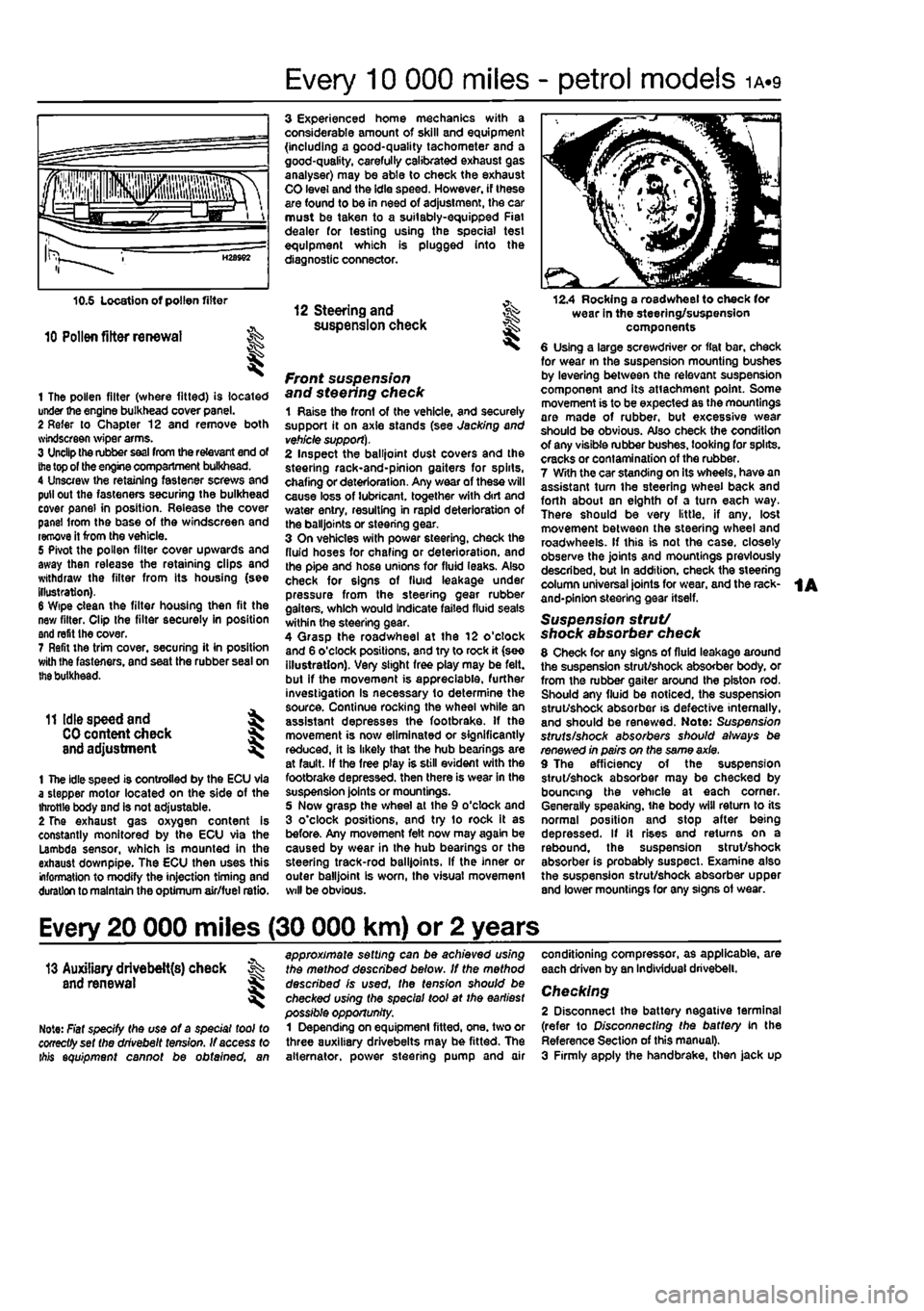
1 The pollen filter (where fitted) is located under the engine bulkhead cover panel. 2 Refer to Chapter 12 and remove both svindscreen wiper arms. 3 Unclip the rubber
seal
from the relevant end of
the
top of the engine compartment bulkhead. 4 Unscrew the retaining fastener screws and pull out the fasteners securing the bulkhead cover panel in position. Release the cover panel Irom the base of the windscreen and remove it from the vehicle. 5 Pivot the pollen filter cover upwards and away then release the retaining clips and withdraw the filter from its housing (see illustration). 6 Wipe clean the filter housing then fit the new filter. Clip the filter securely in position and refit the cover. 7 Refit the trim cover, securing it in position with Ihe fasteners, and seat the rubber seal on
the
bulkhead.
11 Idle speed and ^
CO
content check J and adjustment ^
1 The idle speed is controlled by the ECU via a stepper motor located on the side of the throttle body and is not adjustable. 2 The exhaust gas oxygen content is constantly monitored by the ECU via the Lambda sensor, which is mounted in the exhaust down pipe. The ECU then uses this information to modify the injection timing and duration to maintain the optimum air/fuel ratio.
3 Experienced home mechanics with a considerable amount of skill and equipment (including a good-quality tachometer and a good-quality, carefully calibrated exhaust gas analyser) may be able to check the exhaust CO level and the idle speed. However, if these are found to be in need of adjustment, the car must be taken to a suitably-equipped Fiat dealer for testing using the special test equipment which is plugged into the diagnostic connector.
12 Steering and ^ suspension check
front suspension and steering check 1 Raise the front of the vehicle, and securely support it on axle stands (see Jacking and
vehicle support).
2 Inspect the balljoint dust covers and the steehng rack-and-pinion gaiters for spirts, chafing or deterioration. Any wear of these will cause loss of lubricant, together with dirt and water entry, resulting in rapid deterioration of the balljoints or steering gear. 3 On vehicles with power steering, check the fluid hoses for chafing or deterioration, and the pipe and hose unions for fluid leaks. Also check for signs of fluid leakage under pressure from the steering gear rubber gaiters, which would indicate failed fluid seals within the steering gear. 4 Qrasp the roadwheel at the 12 o'clock and 6 o'clock positions, and try to rock it (see illustration). Very slight free play may be felt, but if the movement is appreciable, further investigation Is necessary to determine the source. Continue rocking the wheel while an assistant depresses the footbrake. If the movement is now eliminated or significantly reduced, it is likely that the hub bearings are at fault. If the free play is still evident with the footbrake depressed, then there is wear in the suspension joints or mountings. 5 Now grasp the wheel at the 9 o'clock and 3 o'clock positions, and try to rock it as before. Any movement felt now may again be caused by wear in the hub bearings or the steering track-rod balljoints. If the inner or outer balljoint is worn, the visual movement will be obvious.
12.4 Rocking a roadwheel to check for wear in the steering/suspension components 6 Using a large screwdriver or flat bar, check for wear in the suspension mounting bushes by levering between the relevant suspension component and its attachment point. Some movement is to be expected as the mountings are made of rubber, but excessive wear should be obvious. Also check the condition of any visible rubber bushes, looking for splits, cracks or contamination of the rubber. 7 With the car standing on its wheels, have an assistant tum the steering wheel back and forth about sn eighth of a turn each way. There should be very little, if any. lost movement between the steering wheel and roadwheels. If this is not the case, closely observe the joints and mountings previously described, but in addition, check the steering column universal joints for wear, and the rack-and-pinion steering gear itself.
Suspension strut/ shock absorber check 8 Check for any signs of fluid leakage around the suspension strut/shock absorber body, or from the rubber gaiter around the piston rod. Should any fluid be noticed, the suspension strut/shock absorber is defective internally, and should be renewed. Note: Suspension struts/shock absorbers should always be renewed in pairs on the same axle. 9 The efficiency of the suspension strut/shock absorber may be checked by bouncing the vehicle at each corner. Generally speaking, ihe body will return to its normal position and stop after being depressed. If it rises and returns on a rebound, the suspension strut/shock absorber is probably suspect. Examine also the suspension strut/shock absorber upper and lower mountings for any signs of wear.
Every 20 000 miles (30 000 km) or 2 years
13 Auxiliary drivebelt{s) check % and renewal ^
Note: Fiat specify the use of a special tool to cooectfyset the drivebelt tension. If access to ibis equipment cannot be obtained, an
approximate setting can be achieved using the method described below. If the method described is used, the tension should be checked using the special tool at the earliest possible opportunity. 1 Depending on equipment fitted, one. two or three auxiliary drivebelts may be fitted. The alternator, power steering pump and air
conditioning compressor, as applicable, are each driven by an Individual drivebelt.
Checking 2 Disconnect the battery negative terminal (refer to Disconnecting the battery in the Reference Section of this manual). 3 Firmly apply the handbrake, then jack up