heater FIAT PUNTO 1999 176 / 1.G Workshop Manual
[x] Cancel search | Manufacturer: FIAT, Model Year: 1999, Model line: PUNTO, Model: FIAT PUNTO 1999 176 / 1.GPages: 225, PDF Size: 18.54 MB
Page 8 of 225
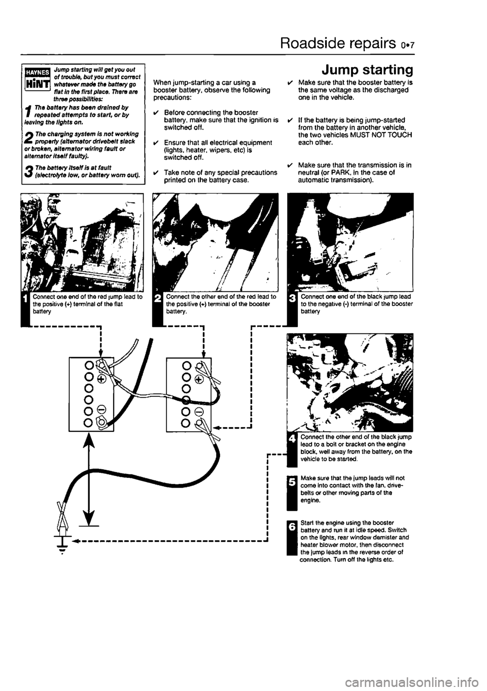
Roadside repairs 0.7
I Jump starting will get you out of trouble, but you must correct | whatever made the battery go fiat in the first place. There are three possibilities:
t
The battery has been drained by repeated attempts to start, or by leaving the lights on.
2
The charging system (s not working property (alternator drivebelt slack or broken, alternator wiring fault or alternator Itself faulty).
3
The battery Itself is at fault (ehctrotyte low, or battery worn out).
When jump-starling a car using a booster battery, observe the following precautions:
• Before connecting the booster battery, make sure that the ignition is switched off.
• Ensure that all electrical equipment (lights, heater, wipers, etc) is switched off.
• Take note of any special precautions printed on the battery case.
Jump starting • Make sure that the booster battery Is the same voltage as the discharged one in the vehicle.
• If the battery is being jump-started from the battery in another vehicle, the two vehicles MUST NOT TOUCH each other.
• Make sure that the transmission is in neutral (or PARK. In the case of automatic transmission).
Make sure that the lump leads will not come into contact with the fan. drive-belts or other moving parts of the engine.
Start the engine using the booster battery and run it at idle speed. Switch on the lights, rear window demister and heater blower motor, then disconnect the jump leads in the reverse order of connection. Turn off the lights etc.
Page 27 of 225
ia«8 Every 10 000 miles - petrol models
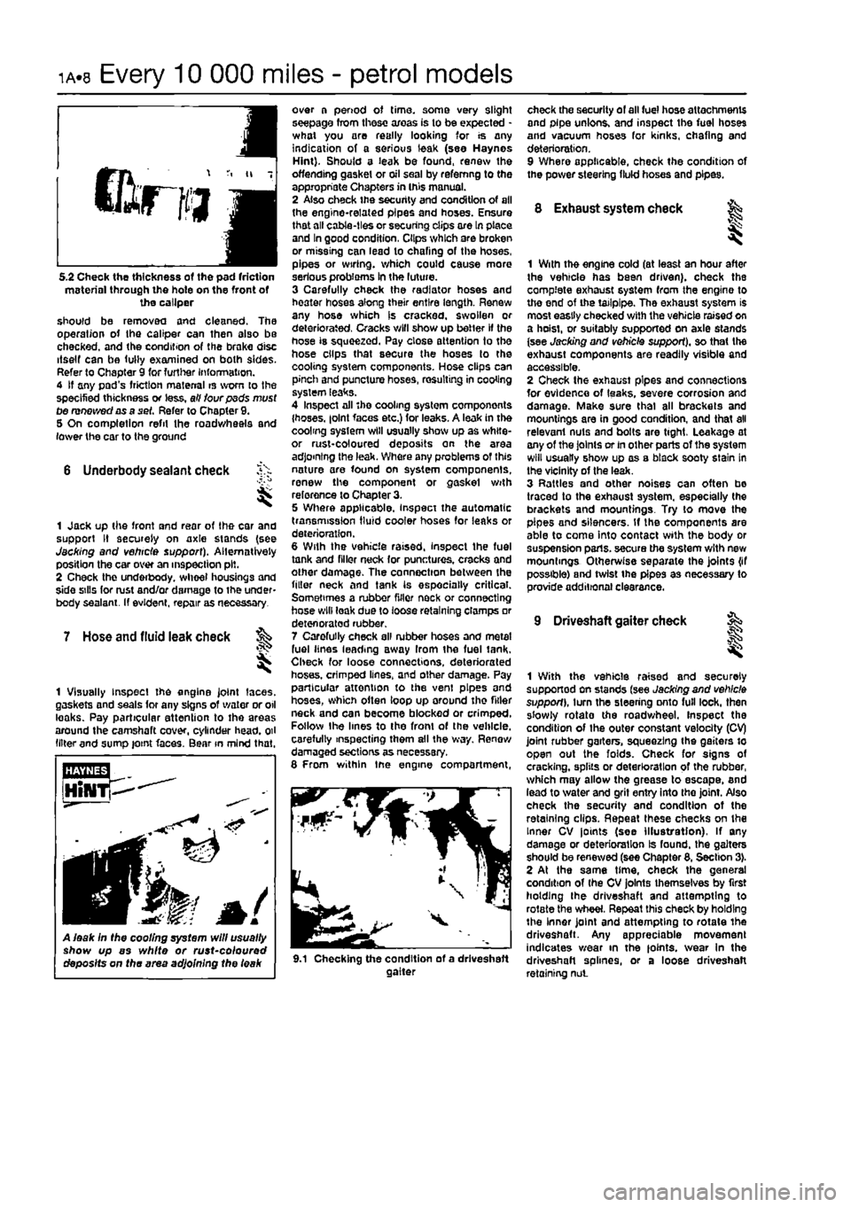
5.2 Check the thickness of the pad friction material through the hole on the front of the caliper should be removed and cleaned. The operation of the caliper can then
bIbo
be checked, and the condition of the brake disc itself can be fully examined on both sides. Refer to Chapter 9 for further Information. 4 If any pad's friction material is worn to the specified thickness or less, all four psds must tie renewed as a set. Refer to Chapter 9. 5 On completion refit the roadwheels and lower the car to the ground
6 Underbody sealant check
I
1 Jack up the front and rear of the car and support It securely on axle stands (see Jacking and vehicle support). Alternatively position the car over an inspection pit. 2 Check the underbody. wheel housings and side sills for rust and/or damage to the under-body sealant. If evident, repair as necessary.
7 Hose and fluid leak check ^
I
1 Visually Inspect the engine joint laces, gaskets and seals for any signs of water or oil leaks. Pay particular attention to the areas around the camshaft cover, cylinder head, oil (liter and sump joint faces. Bear in mind that.
A leak In the cooling system will usually show up as white or rust~coloured deposits on the area adjoining the leak
over a period of time, some very slight seepage from these areas is to be expected -what you are really looking for is any indication of a serious leak (see Haynes Hint). Should a leak be found, renew the offending gasket or oil seal by refemng to the appropriate Chapters in this manual. 2 Also check the security and condition of all the engine-related pipes and hoses. Ensure that all cable-ties or securing clips ore In place and In good condition, Clips which are broken or missing can lead to chafing of the hoses, pipes or wiring, which could cause more serious probioms In the luture. 3 Carefully check the radiator hoses and heater hoses along their entire length. Renew any hose which is cracked, swollen or deteriorated, Cracks will show up better if the hose is squeezed. Pay close attention to the hose clips that secure the hoses to the cooling system components. Hose clips can pinch and puncture hoses, resulting in cooling system leaks. 4 Inspect all 'he cooling system components {hoses. |olnt faces etc.) for leaks. A leak in the coolmg system will usually show up as white-or rust-coloured deposits on the area adjoining the leak. Where any problems of this nature are found on system components, renew the component or gaskel with reference to Chapter 3. 5 Where applicable, inspect the automatic transmission fluid cooler hoses for leaks or deterioration. 6 With the vehicle raised, inspect the fuel tank and filler neck for punctures, cracks and other damage. The connection between the filler neck and tank Is especially critical. Sometimes a rubber filler neck or connecting hose will leak due to loose retaining clamps or deten orated rubber. 7 Carefully check all rubber hoses and metal fuel lines leading away Irom the fuel tank. Check for loose connections, deteriorated hoses, crimped lines, and other damage. Pay particular attention to the vent pipes and hoses, which often loop up around the fitter neck and can become blocked or crimped. Follow the lines to the front of the vehicle, carefully inspecting them all the way. Renew damaged sections as necessary. 8 From within tne engine compartment,
check the security of all fuel hose attachments and pipe unions, and inspect the fuel hoses and vacuum hoses for kinks, chafing and deterioration. 9 Where applicable, check the condition of the power steering fluid hoses and pipes.
8 Exhaust system check fe
1 With the engine cold (at least an hour after the vehicle has been driven), check the complete exhaust system from the engine to the end of the tailpipe. The exhaust system is most easily checked with the vehicle raised on a hoist, or suitably supported on axle stands (see Jacking and vehicle support), so that the exhaust components are readily visible and accessible. 2 Check the exhaust pipes and connections for evidence of leaks, severe corrosion and damage. Make sure thai all brackets and mountings are in good condition, and that all relevant nuts and bolts are tight, Leakage at any of the Joints or in other parts of the system will usually show up as a black sooty stain in the vicinity of the leak. 3 Rattles and other noises can often bo traced to the exhaust system, especially the brackets and mountings. Try to move the pipes and silencers. If the components are able to come Into contact with the body or suspension parts, secure the system with new mountings Otherwise separate the joints {if possible) and twist the pipes as necessary to provide additional clearance.
9 Driveshaft gaiter check
9.1 Checking the condition of a driveshaft gaiter
1
1 With the vehicle raised and securely supported on stands (see Jacking and vehicle support), turn the steering onto full lock, then s'owly rotate the roadwheel. Inspect the condition of Ihe outer constant velocity (CV) joint rubber garters, squeezing the gaiters to open out the folds. Check for signs of cracking, splits or deterioration of the rubber, which may allow the grease to escape, and lead to water and grit entry into the joint. Also check the security and condition of the retaining clips. Repeat these checks on the Inner CV joints (see Illustration), If any damage or deterioration Is found, the gaiters should be renewed (see Chapter 8, Section 3). 2 At the same time, check the general condition of (he CV joints themselves by first holding (he driveshaft and attempting to rotate the wheel. Repeat this check by holding the inner joint and attempting to rotate the driveshaft. Any appreciable movement indicates wear in the joints. wear In the driveshaft splines, or a loose driveshaft retaining nut
Page 35 of 225
ia.16 Every 2 years - petrol models
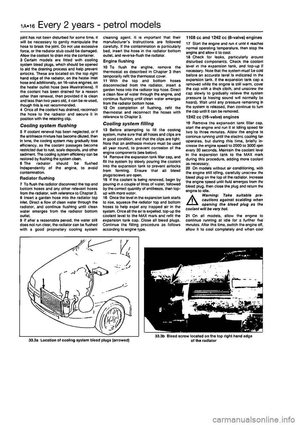
joint has not been disturbed for some time, if will bo necessary to gently manipulate the hose to break the joint. Do not use excessive force, or the radiator stub could be damaged. Allow the coolant to drain Into the container. 3 Certain models are fitted with cooling system bleed plugs, which should be opened to aid the draining process and help prevent airlocks. These are located on the top right hand edge of the radiator, on the heater Inlet hose and additionally, on 16-valve engines, on the heater outlet hose (see illustrations). If the coolant has been drained for a reason other than renewal, then provided It is ciean and less than two years old, it can be re-used, though this is not recommended. 4 Once ail the coofant has drained, reconnect the hose to the radiator and secure it in position with the retaining clip.
Cooling system flushing 5 If coolant renewal has been neglected, or If the antifreeze mixture has become diluted, then in time, Ihe cooling system may gradually lose efficiency, as the coolant passages become restricted due to rust, scale deposits, and other sediment. The cooling system efficiency can be restored by flushing the system clean. 6 The radiator should be flushed Independently of the engine, to avoid contamination. Radiator flushing 7 To flush the radiator disconnect the top and bottom hoses and any other relevant hoses from the radiator, with reference to Chapter 3. 8 Insert a garden hose into the radiator top inlet. Direct a flow of clean v/ater through the radiator, and continue flushing until clean water emerges from the radiator bottom outlet. 9 If after a reasonable period, the water still does not run clear, the radiator can be flushed wilh a good propnetary cooling system
cleaning agent. It is important that their manufacturer's Instructions are followed carefully. If the contamination is particularly bad, insert the hose in the radiator bottom outlet, and reverse-flush the radiator. Engine flushing 10 To flush the engine, remove the thermostat as described In Chapter 3 then temporarily refit the thermostat cover. 11 With the top and bottom hoses disconnected from the radiator, insert a garden hose into the radiator top hose. Direct a clean flow of water through the engine, and continue flushing until clean water emerges from the radiator bottom hose. 12 On complotion of flushing, refit the thermostat and reconnect the hoses with reference to Chapter 3,
Cooling system filling 13 Before attempting to fill the cooling system, make sure that all hoses and clips are in good condition, and that the clips are tight. Note that an antifreezo mixture must be used all year round, to prevent corrosion of the engine components (see below). 14 Remove the expansion tank filler cap. and fill the system by slowly pouring the coolant Into the oxpansion lank to prevent airlocks from forming. Ensure that all bleed plugs/screws are open. 15 If the coolant Is being renewed, begin by pouring in a couple of litres of v/ater, followed by the correct quantity of antifreeze, then top-up with more water. 16 Once the level in the expansion tank starts to rise, squeeze the radiator top and bottom hoses to help expel any trapped air In the system. Once all the air is expelled, top-up the coolant level to the MAX mark and refit the expansion tank cap. Close all bleed plugs. Continue the filling procedure as follows according to engine type.
1108 cc and 1242 cc (8-vaive) engines 17 Start the engine and run it until tt reaches normal operating temperature, then stop the engine and allow it to cool. 18 Chock for teaks, particularly around disturbed components. Check the coolant level in the expansion tank, and top-up H necessary. Note that the system must be coW before an accurate level Is indicated in the oxpansion tank. If the expansion tank cap is removed while the engine Is still warm, cover Ihe cap with a thick cloth, and unscrew the cap slowly to gradually relieve the system pressure (a hissing sound will normally be heard). Wall until any pressure remaining In the system is released, then continue to turn the cap until It can be removed. 1242 cc (16-valve) engines 19 Remove the expansion tank filler cap. start the engine and run it at Idling speed for two to three minutes. Allow the engine to continue running until the electric cooling fan operates, but during this time, briefly in-crease the engine speed to 2000 to 3000 rpm every 30 seconds. Maintain the coolant level in the expansion tank to the MAX mark during tliis procedure, adding more coolant as necessary. 20 On models without air conditfoning, wilh the engine still idling, carefully unscrew the bleed plug on the top of the radiator. Increase the engine speed until fluid emerges from the bleed plug, then close the plug and return the engine to idle.
A
Warning: Take suitable pre-cautions against scalding when opening the bleed plug as the coolant will be very hot. 21 On all models, allow the engine to continue running at idle for a further five minutes. After this time, switch the engine ofl, allow it 1o cool completely and when cool
Page 40 of 225
ib-4 Component location - diesel models
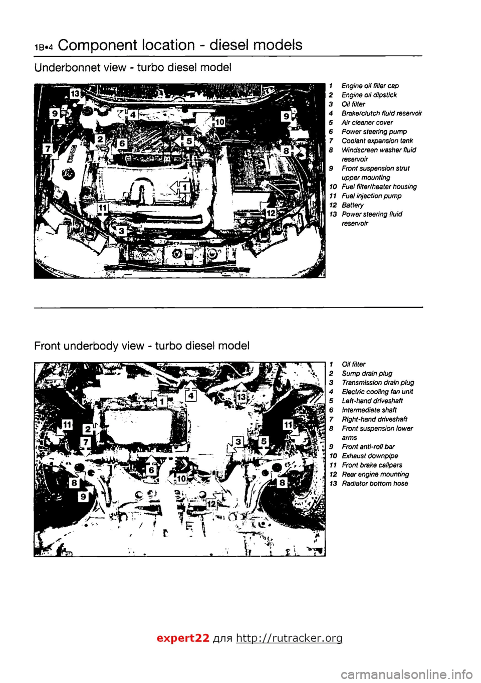
Underbonnet view - turbo diesel model
1 Engine oil filter
cap
2 Engine oil dipstick 3 Oil
tilter
4 Brake/clutch fluid
reservoir
5 Air cleaner
cover
6 Power steering pump 7 Coolant expansion
tank
8 Windscreen washer
fluid
reservoir 9 Front suspension strut upper mounting 10 Fuel filter/heater
housing
11
Fuel
injection pump 12 Battery 13 Power steering fluid reservoir
Front underbody view - turbo diesel model
1 Oil
fitter
2 Sump drain plug 3 Transmission drain plug 4 Electric cooling fan unit 5 Left-hand
driveshaft
6 Intermediate
shaft
7 Bight-hand
driveshaft
8 Front suspension lower arms 9 Front anti-roll
bar
10 Exhaust downpipe 11 Front brake calipers 12
Rear
engine mounting 13 Radiator bottom hose
expert22 fl/ia http://rutracker.org
Page 43 of 225
Maintenance procedures - diesel models ib.?
Every 10 000 miles (15 000 km) or 12 months
5 Brake warning lamp operation check 1
1 With Ihe ignition Key inserted and turned to the MAR position, open the bonnet and depress the button on the top of the brake
fluid
reservoir cap (see illustration). I
As
the button is pressed, the brake warning
lamp
on the instrument panel should light. 3 If Ihe lamp fails to illuminate, check the operation of the level switch using a continuity taster, then refer to Chapter t2, Section 5,
and
check the Instrument panel bulb.
6 Front brake pad check ^
I
1 firmly apply Ihe handbrake, then jack up the front of the car and support it securely on arie stands (see Jacking and vehicle support). Remove the front roadwheels. 2 Using a steel rule, measure the thickness of
the
friction material of the brake pads on both brakes. This must not be less than 1.5 mm. Ctefc the thickness of the pad friction material through the hole on the front of the caliper
|see
lustration), 3
For a
comprehensive check, the brake pads should be removed and cleaned. The operation of the caliper can then also bo checked, and the condition of the brake disc iteeil can be fully examined on both sides. Refer to Chapter 9 for further Information. 4 If any pad's friction material Is worn to the specified thickness or less, all lour pads must to renewed as a set. Refer to Chapter 9. 5 On completion refit the roadwheels and lower the car to the ground.
7 Underbody sealant check f^
1 Jack up the front and rear of the car and support on axle stands (see Jacking and
vehicle
support). Alternatively position the car over
an
Inspection pit. 2 Check the complete underbody, wheel housings and side sills for corrosion and/or damage to the underbody sealant. If evident,
rapairi
8
Hose
and fluid leak check
1 Visually inspect the engine Joint faces. g3skets and seals for any signs of water or oil leaks. Pay particular attention to the areas
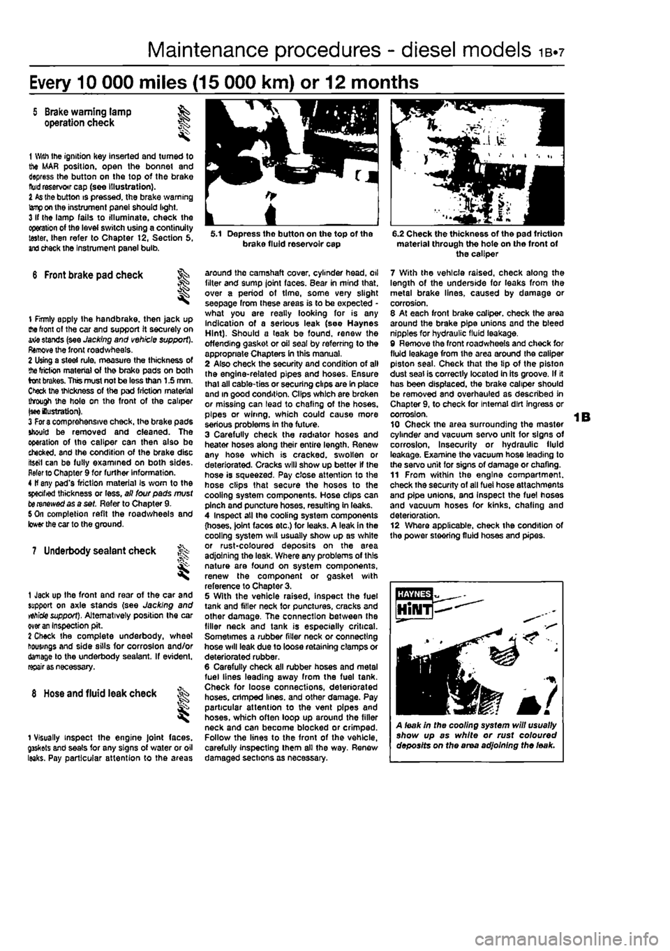
5.1 Depress tho button on the top of the brake fluid reservoir cap
around the camshaft cover, cylinder head, oil filter and sump joint faces. Bear in mind that, over a period of time, some very slight seepage from these areas is to be expected -what you are really looking for is any indication of a serious leak (see Haynes Hint). Should a teak be found, renew the offending gasket or oil seal by referring to the appropriate Chapters In this manual, 2 Also check the security and condition of all the engine-related pipes and hoses. Ensure thai all cable-ties or securing clips are In place and in good condition. Clips which are broken or missing can lead to chafing of the hoses, pipes or wiring, which could cause more serious problems In the future. 3 Carefully check the radiator hoses and heater hoses along their entire length. Renew any hose which is cracked, swollen or deteriorated. Cracks will show up better If the hose is squeezed. Pay close attention to the hose clips that secure the hoses to the cooling system components. Hose clips can pinch and puncture hoses, resulting in leaks. 4 Inspect all the cooling system components (hoses. )olnt faces etc.) for leaks. A leak in the cooling system will usually show up as white or rust-coloured deposits on the area adjoining the leak, Where any problems of this nature are found on system components, renew the component or gasket with reference to Chapter 3. 5 With the vehicle raised, inspect the fuel tank and filler neck for punctures, cracks and other damage, The connection between the filler neck and tank is especially critical. Sometimes a rubber filler neck or connecting hose will leak due to loose retaining clamps or deteriorated rubber. 6 Carefully check all rubber hoses and metal fuel lines leading away from the fuel tank. Check for loose connections, deteriorated hoses, crimped lines, and other damage. Pay particular attention to the vent pipes and hoses, which often loop up around the filler neck and can become blocked or crimped. Follow the lines to the front of the vehicle, carefully Inspecting them all the way. Renew damaged sections as necessary.
6.2 Check the thickness of the pad friction material through the hote on the front of the caliper
7 With the vehicle raised, check along the length of the underside for leaks from the metal brake lines, caused by damage or corrosion. 8 At each front brake caliper, check the area around the brake pipe unions and the bleed nipples for hydraulic fluid leakage, 9 Remove the front roadwheels and chock for fluid leakage from the area around the caliper piston seal. Check that the tip of the piston dust seal is correctly located in its groove. If it has been displaced, the brake caliper should be removed and overhauled as described in Chapter 9, to check for internal dirt Ingress or corrosion. 10 Check the area surrounding the master cylinder and vacuum servo unit for signs of corrosion, Insecurity or hydraulic fluid leakage. Examine the vacuum hose leading to the servo unit for signs of damage or chafing. 11 From within the engine compartment, check the security of all fuel hose attachments and pipe unions, and Inspect the fuel hoses and vacuum hoses for kinks, chafing and deterioration. 12 Where applicable, check the condition of the power steering fluid hoses and pipes.
A leak in the cooling system will usually show up as white or rust coloured deposits on the area adjoining the leak.
Page 44 of 225
ib-8 Every 10 000 miles - diesel models
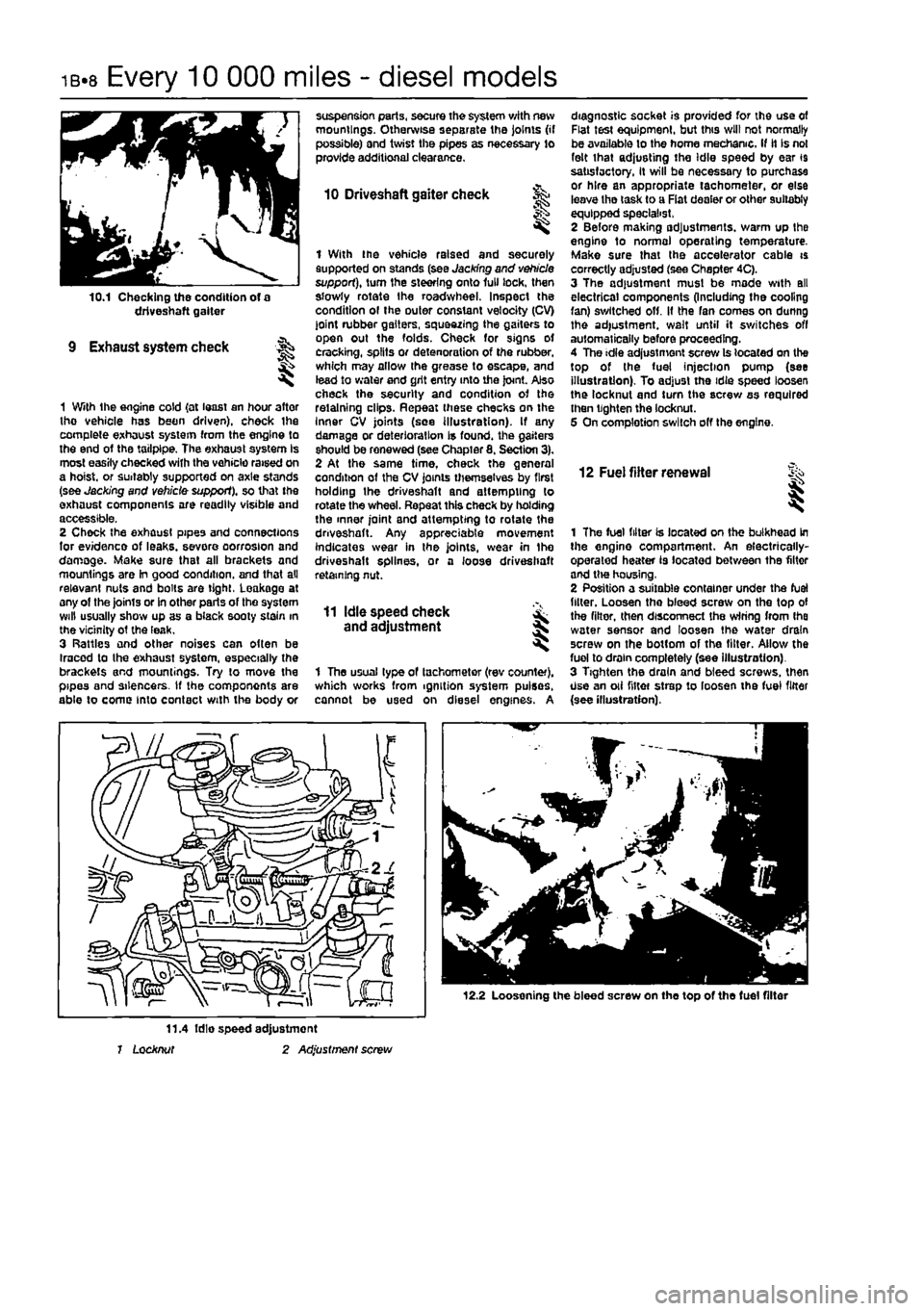
10.1 Checking the condition of a driveshaft gaiter
9 Exhaust system check
1 With the engine cold {at least an hour after tho vehicle has been driven), check ihe complete exhaust system from the engine to the end of the tailpipe. The exhaust system Is most easily checked with the vehicle raised on a hoist, or suitably supported on axle stands (see Jacking and vehicle support), so that the exhaust components are readily visible and accessible. 2 Check the exhaust pipes and connections for evidence of leaks, severe oorrosion and damage. Make sure that all brackets and mountings are In good condition, and that all relevant nuts and bolts are tight, Leakage at any of the joints or in other parts of tho system will usually show up as a black sooty stain in the vicinity ot the leak. 3 Rattles and other noises can often be Iracod to the exhaust system, especially the brackets and mountings. Try to move the pipes and silencers. If the components are able to come into contact with the body or
suspension parts, secure the system with new mountings. Otherwise separate the joints (if possible) and twist the pipes as necessary to provide additional clearance.
10 Driveshaft gaiter check
I
1 With the vehicle raised and securely supported on stands (see Jacking and vehicle support), turn the steering onto lull lock, then slowly rotate the roadwheel. Inspect the condition ol the outer constant velocity (CV) joint rubber gaiters, squeezing the gaiters to open out the folds. Check for signs ot cracking, splits or detenoration of the rubber, which may allow the grease to escape, and lead to water and grit entry into the joint. Also check the security and condition of the retaining clips. Repeat these checks on the Inner CV joints (see illustration). If any damage or deterioration is found, the gaiters should be renewed (see Chapter 8. Section 3). 2 At the same time, check the general condition of the CV joints themselves by first holding the driveshaft and attempting to rotate the wheel. Repeat this check by holding the inner joint and attempting to rotate the driveshaft. Any appreciable movement indicates wear in the joints, wear in Ihe driveshaft splines, or a loose driveshaft retaining nut.
11 Idle speed check and adjustment
1 The usual type of tachometer (rev counter), which works from ignition system pulses, cannot be used on diesel engines. A
diagnostic socket is provided for the use of Flat test equipment, but this will not normally be available to the home mechanic. If it Is not felt that adjusting the Idle speed by ear 19 satisfactory, It will be necessary to purchase or hire an appropriate tachometer, or else leave tho task to a Fiat dealer or other suitably equipped specialist, 2 Before making adjustments, warm up the engine to normal operating temperature. Make sure that the accelerator cable is correctly adjusted (see Chapter 4C). 3 The adjustment must be made with all electrical components (Including the cooling fan) switched off. It the fan comes on dunng the adjustment, wait until it switches off automatically before proceeding. 4 The idle adjustment screw Is located on the top of the fuel injection pump (see illustration). To adjust the idie speed loosen the locknut and turn the screw as required then tighten the locknut. 5 On completion switch off the engine.
12 Fuel filter renewal i
1 The fuel filter is located on the bulkhead in the engine compartment. An electrically-operated heater is located between the filter and tlw housing, 2 Position a suitable container under the fuel filler. Loosen tho bleed screw on the top of the filter, then disconnect the wiring from Ihe water sensor and loosen the water drain screw on the bottom of the filter. Allow the fuel to drain completely (see illustration). 3 Tighten the drain and bleed screws, then Use an oii niter strep to loosen the fuel filter {see illustration).
12.2 Loosening the bleed screw on the top of the fuel filter
11.4 fdie speed adjustment 1 Locknut 2 Adjustment screw
Page 71 of 225
DOHC (16-valve) petrol engine in-car repair procedures 2B*11
camshaft cover plate... 25 Locate the cam follower retaining tools in position and refit the cylinder head extension
as
described In Section 8.
10
Cylinder head - &
removal and
refitting S
Removal Note; The cylinder head bolts are of special
sekned
design and a Fiat tool should be
obtained
to unscrew them. A Ton key will not
JSt however
in practise It was found that a dose-httlng Alien key could be used as an itemative. 1 Drain the cooling system as described in Chapter 1A. 2 Remove the cylinder head extension as oescAbed
m
Section 8. 3 Disconnect the radiator hose from the thermostat housing on the left-hand end of
Ihe
cylinder head. 4 Disconnect the heater hose from the outlet
at the
rear of the cylinder head. 5 Disconnect the coolant temperature sensor md temperature gauge sensor wiring plugs
torn
the left-hand end of the cylinder head. 9 Undo the engine oil dipstick tube bracket retaining bolt and the two bolts securing the wing harness support clips to the inlet marriold lower section. 7 Undo Ihe retaining nuts and separate the ixhaust system front pipe from the exhaust manifold flange.
8
Check that nothing remains attached to the cinder head likely to impede removal. It Is assumed that the head will be removed complete with exhaust manifold and inlet manifold lower section. 9 Unscrew the cylinder head bolts half a turn K
e
time in the reverse order to that shown in (lustration 10.20a. When the bolts are free. «mwe them from their locations.. Id Lift the cylinder head from the block. If it is stuck tight rock the head to break the joint by mans of the manifolds. On no account drive
levers
into the gasket Joint, nor attempt to tap tf« head sideways, as it is located on positioning dowels. 11 Remove and discard the cylinder head gasket.
JK'
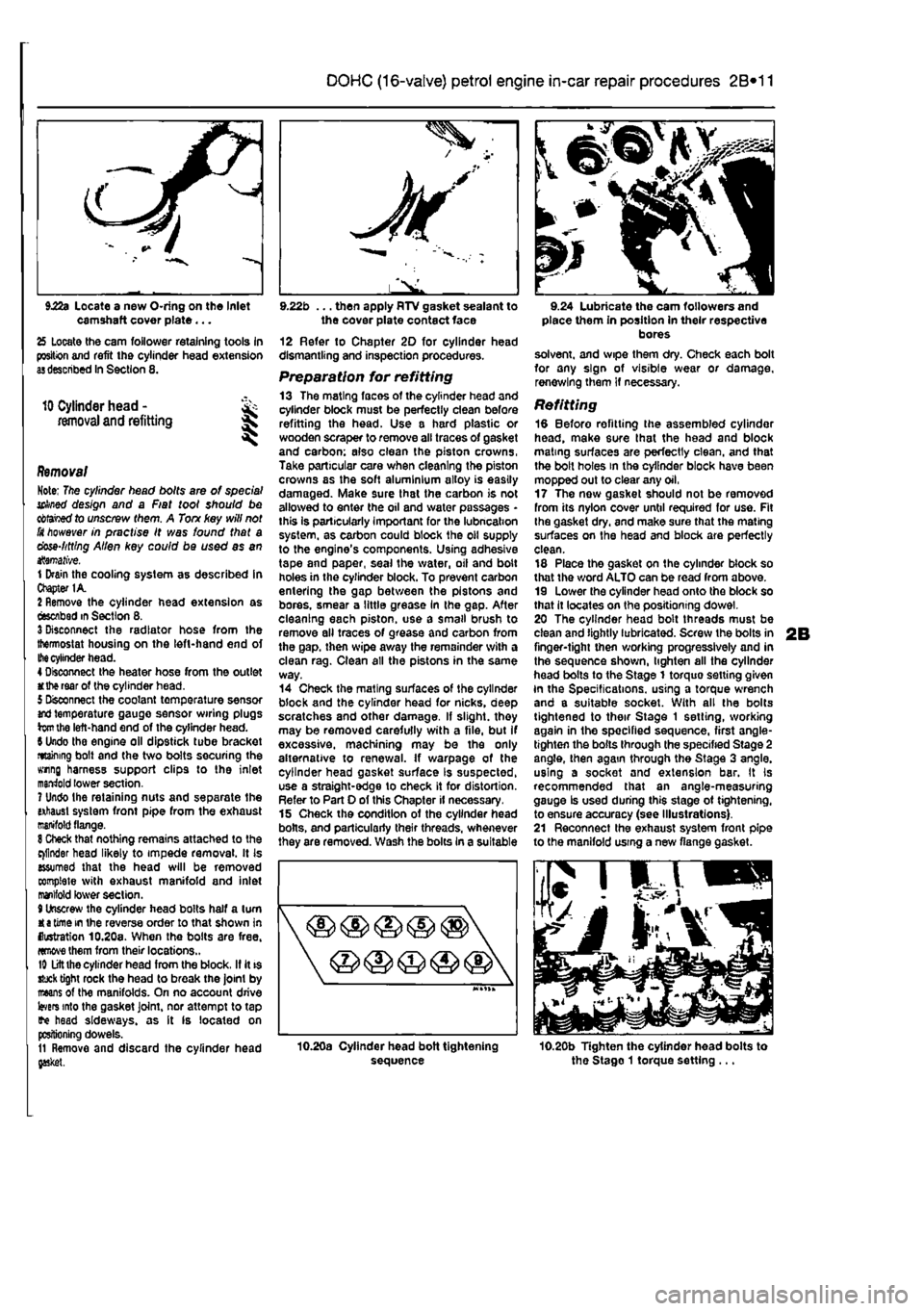
l^. 9.22b ... then apply RTV gasket sealant to the cover plate contact face 12 Refer to Chapter 20 for cylinder head dismantling and inspection procedures. Preparation for refitting 13 The mating faces of the cylinder head and cylinder block must be perfectly dean before refitting the head. Use a hard plastic or wooden scraper to remove all traces of gasket and carbon; also clean the piston crowns, Take particular care when cleaning the piston crowns as the soft aluminium alloy is easily damaged. Make sure that the carbon is not allowed to enter the oil and water passages -this Is particularly important for the lubncahon system, as carbon could block the oil supply to the engine's components. Using adhesive tape and paper, seal the water, oil and bolt holes in the cylinder block. To prevent carbon entering the gap between the pistons and bores, smear a little grease In the gap. After cleaning each piston, use a small brush to remove all traces of grease and carbon from the gap. then wipe away the remainder with a clean rag. Clean all the pistons in the same way. 14 Check the mating surfaces of the cylinder block and the cylinder head for nicks, deep scratches and other damage. If slight, they may be removed carefully with a file, but If excessive, machining may be the only alternative to renewal. If warpage of the cylinder head gasket surface Is suspected, use a straight-edge to check it for distortion. Refer to Part 0 of this Chapter if necessary. 15 Check the condition of the cylinder head bolts, and particularly their threads, whenever they are removed. Wash the bolts In a suitable
sequence
9.24 Lubricate the cam followers and place them in position in their respective bores solvent, and wipe them dry. Check each bolt for any sign of visible wear or damage, renewing them if necessary.
Refitting 18 Before refitting the assembled cylinder head, make sure that the head and block mating surfaces are perfectly clean, and that the bolt holes in the cylinder block have been mopped out to clear any oil, 17 The now gasket should not be removed from its nylon cover until required for use. Fit Ihe gasket dry, and make sure that the mating surfaces on the head and block are perfectly clean. 18 Place the gasket on the cylinder block so that the word ALTO can be read from above. 19 Lower the cylinder head onto the block so that it locates on the positioning dowel. 20 The cylinder head bolt threads must be clean and lightly lubricated. Screw the bolts in finger-tight then working progressively and in the sequence shown, lighten all the cylinder head bolts to the Stage 1 torquo setting given In the Specifications, using a torque wrench and a suitable socket. With all the bolts tightened to their Stage 1 setting, working again in the specified sequence, first angle-tighten the bolts through the specified Stage 2 angle, then again through the Stage 3 angle, using a socket and extension bar. It Is recommended that an angle-measuring gauge Is used during this stage ot tightening, to ensure accuracy (see Illustrations). 21 Reconnect the exhaust system front pipe to the manifold using a new flange gasket.
10.20b Tighten the cylinder head bolts to the Stago 1 torque setting ...
Page 72 of 225
2B*12 DOHC (16-valve) petrol engine in-car repair procedures
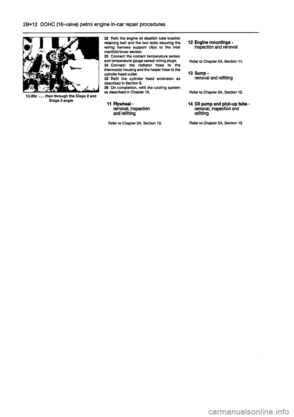
... then through the Stage 2 end Stage 3 angle
22 Refit the engine oil dipstick tube bracket retaining bolt and the two bolts securing the wiring harness support clips to the inlet manifold lower section. 23 Connect the coolant temperature sensor and temperature gauge sensor wiring plugs. 24 Connect the radiator hose lo the thermostat housing and the heater hose to the cylinder head outlet. 25 Refit the cylinder head extension as described in Section 8. 26 On completion, refill tha cooling system as described In Chapter 1A.
11 Flywheel -removal, Inspection arid refitting
12 Engine mountings -inspection and renewal
Refer to Chapter 2A, Section 11.
13 Sump -removal and refitting
R6fer to Chapter 2A. Section 12.
14 Oil pump and pick-up tube -removal, Inspection and refitting
Refer to Chapter 2A, Section 10. Refer to Chapter 2A. Section 13.
Page 74 of 225
2C*2 Diesel engine in-car repair procedures
1 General information
Using this Chapter Chapter 2 is divided Into four Parts; A. 8, C and 0. Repair operations that cart be carried out with the engine in the vehicle are described In Part A, SOHC (B-valve) petrol engines. Part B, DOHC (16-valve) petrol engines and Part C. diesel engines, Part D covers the removal of the engine/transmission as a unit, and describes the engine dismantling and overhaul procedures. In Parts A. 8 and C. the assumption Is made that the engine is installed in Ihe vehicle, with all anciliaries connected If the engine has been removed for overhaul, the preliminary dismantling information which precedes each operation may be ignored.
Engine description Both normally aspirated (non-turbo) and turbocharged diesel engines are fitted to the Punto range. The engines together with their codes are given in the Specifications at the start of lhis Chapter. The engines are water-cooled, single-overhead camshaft. In-line lour cylinder units with cast-iron cylinder blocks and aluminium-alloy cylinder heads. The engine is mounted transversely at the front of the vehicle, with the transmission bolted to the left-hand side of the engine. The cylinder head carries the camshaft which is driven by a toothed timing belt. It also houses the inlet and exhaust valves which are closed by single coll valve springs and run in valve guides pressed into the cylinder head. The valves are operated by cam followers fitted over each valve, and the clearances are adjusted by shims positioned between the followers and the camshaft lobes. The camshaft is supported by four bearings • the end bearings are machined in the cylinder head and the remaining bearings have caps bolted to the cylinder head. The cylinder head contains integral oiiways which supply and lubricate the camshaft and followers and it also Incorporates renewable swirl chambers. The crankshaft Is supported by five main bearings, and endfloat Is controlled by a thrust bearing fitted on the rear main bearing. All diesel engines are fitted with a brake servo vacuum pump dnven from the left-hBnd end of the camshaft. Engine coolant is circulated by a pump, driven by the auxiliary drivebeit. For details of the cooling system refer to Chapter 3. Lubricant is circulated under pressure by a pump, driven from the front of the crankshaft. Oil is drawn from the sump through a strainer, and then forced through an externally-mounted, replaceable screw-on filter. From there, it is distributed to the cylinder head.
where il lubncates the camshaft journals and followers, and also to the crankcase, where it lubricates the main bearings, connecting rod big- and small-ends, gudgeon pins and cylinder bores. Oil jets are fitted to the base of each cylinder bore - these spray oil onto the underside of the pistons, lo Improve cooling. An oil cooler is also fitted to reduce the temp-erature of oil before it re-enters the engine.
Repair operations possible with the engine in the car The following work can be carried out with the engine in the can a) Compression pressure - testing b) Auxiliary drivebeit - removal and refitting (refer to Chapter rej c) Valve clearances • checking and adjustment (refer to Chapter 1B) d) Camshaft cover - removal and refitting e) Tim/ng belt and covers • removal and refitting 0 Timing belt tensioner and sprockets -removal and refitting g) Cylinder head - removal and refitting' h) Camshaft and cam followers - removal end refitting' I) Camshaft oil seal - renewal j) Crankshaft oil seals - renewal k) Flywheel • removal, inspection and refitting I) Engine mountings - inspection and renewal m)Sump • removal and refitting n) Oil pump and pick-up tube assembly -removal, inspection and refitting 'Cylinder head dismantling procedures are detalfed In Chapter 2D, with details of camshaft and cam follower removal. Note: It ts possible to remove the pistons and connecting rods (after removing the cylinder nead and sump) without removing the engine. However, this is not recommended. Work of this nature is more easily and thoroughly completed with the engine on tho bench as described in Chapter 2D.
2 Location of
TDC
on ^ No
1
cylinder ||
General information 1 The camshaft and fuel Injection pump are driven by the crankshaft, by means of sprockets and a timing belt. All three sprockets rotate in phase with each other and this provides the correct valve and injection pump timing as the engine rotates. When the timing bell is removed during servicing or repair, it is possible for the camshaft, injection pump and crankshaft to rotate independently of each other and the correct timing Is then lost.
2 It
Location of TDC on cylinder No
1
6 Remove the air inlet ducting as described ft Chapter 4C, Section 2. 7 Remove the heater glow plugs with reference to Chapter 5C. Due to the high compression ratio of diesel engines this Is necessary to allow the engine to be turned by hand. 8 Unscrew the mounting bolts and move the coolant expansion tank to one side for access to the timing covers. Release the hose from the clips on Ihe camshaft cover. 9 Release the toggle clips and remove the upper timing cover (see illustration),
2.9 Removing the upper timing cover
Page 80 of 225
2C*2 Diesel engine in-car repair procedures
Refitting 6 Locate a new gasket on the cylinder head and make sure tt Is correctly seated. 7 Lower the cover onto the gasket making sure the gasket Is not displaced, 8 Insert the mounting bolts and tighten them securely In a progressive sequence. Position Ihe support brackets as noted during removal. 9 Clip ihe coolant hoses in position then refil the air ducting.
7 Camshaft oil seal -renewal
8 Crankshaft oil seals -renswal I
9 Cylinder head -
removal
and refitting
1 Remove the timing belt and camshaft sprocket as descnbed in Sections 4 and 5. 2 Using a suitable hooked instrument, remove tho oil seal from the cylinder head taking care nol to damage the surface of the camshafl. Alternatively drill a small hole In tho oil seal and Insert a self-topping screw - the seal can then be removed by pulling on the screw with a pair of pliers. 3 Clean the seating In the cylinder head and tho end of the camshaft To prevent damage to the new oil seal as It is being fitted, wrap some adhesive tape around the end ol the camshaft and lightJy oil it. 4 Dip tho new ail s«al In oil then locate it over Ihe camshaft making sure that the sealing lips are facing inwards. 5 Using a suitable tubular drift, drive the oil seal squarely into the cylinder h*ad. Remove the adhesive tap© 6 Refit the camshaft sprocket and timing belt with reference to Sections 6 and 4.
Front (right-hand side) oil seal t The front oil seal is located in the oil pump casing on the front of the crankshaft. Remove the timing belt as described in Section 4 and the crankshaft sprocket as described in Section 5, 2 Using a suitable hooked instrument, remove the oil seal from the oil pump casing taking care not to damage the surface of the crankshaft. Alternatively drill a small hole In the oil soal and insert a self-tapping screw - the seal can then be removed by pulling on the screw with a pair of pliers. 3 Clean the seating in the oH pump and the surface of the crankshaft. To prevent damage to the new off seal as It Is being fitted, wrap some adhesive tape around the end of tha crankshaft and lightly oil it. 4 Oip the new oii seal In oil then otter it up to the oil pump casing making sure that the sealing Hps are facing inwards,
8.Ba Rear oil soal and housing
5 Using a suitable tubular drift, driva the oil sea! squarely into the casing. Remove the adhesive tape. 6 Refit the crankshaft sprocket and timing belt with reference to Sections 5 and 4.
Rear (left-hand side) oil seal Note: The following paragraphs describe renewal of the rear oil seal leaving the housing In position. The alternative mathod is to remove the housing and renew the oil seel on the bench, however there is then the possibility of damaging the sump gasket. Refer to Chapter 2D for details of removing the mar oil sea! housing. 7 Ramove the flywheel as described in Section 10. 8 Using a suitable hooked Instrument. remove 1he oil seat from the roar oil seal housing taking care not to damage Ihe surface of Ihe crankshaft. Alternatively dnll a small hole In the o» seal and insert a self-tapping screw - the seal can ihan be removed by pulling on the screw with a pair of pliers (see Illustrations), 9 Clean the seating in the housing and the surface of the crankshaft. Check the crankshaft for burrs which may damage the oil seal tip of tno new saal, and It necessary use a Una file to removothem. 10 Dip the new soal in clean engine oil and carefully tocato it over tho crankshafl rear Range making sure that
H
the correct way round. 11 Progressively tap the oH seal into the housing keepfng it square to prevent distortion. A block of wood is useful for this purpose. 12 Refit the flywheel with reference to Section 10.
I
5.8b Using a self-tapping screw and pliers to remove the rear oil seal
Removal Note: The cylinder head bolts are of special splined design and a Fiat tool should be obtained to unscrew them. A Torn key will
not
fit however In practise It was found that a close-fitting Allen key could bo used as an alternative. 1 Disconnect the battery negative terminal (refer to Disconnecting the battery in the Reference Section of this manual), 2 Remove tha battery as described In Chapter 5A. 3 Refer to Chapter IB and carry out the following: o) Drain the engine oil, b) Drain the cooling system. 4 Remove the timing belt as described in Section 4. 5 Unbolt and remova the relay guard and bracket from the left-hand side of the engine. 6 Unbolt and remove the battery mounting tray and disconnect the wiring and lines from the modulator valva and relays. 7 Remove the air eleanar assembly and air duct with reference lo Chapter 4C. 8 Loosen the clip and disconnect the vacuum hosa from the vacuum pump on the left-hand end of the cylinder head. 9 Loosen Ihe clips and disconnect the radiator top hose from the cylinder head outlet. Also disconnect the heater inlet hose from the thermostat housing, 10 Loosen the clips and disconnect the expansion tank and heater outlet hoses. 11 Identify all wiring connectors then disconnect them from the cylinder head, 12 Unscrew the expansion tank mounting screws, then disconnect tha expansion tank hoses at their connections to the engine. Remove the expansion tank from tha engine compartment. 13 Release tha clip and disconnect ihe crankcase breather from the left-hand rear of the cylinder head. 14 Unbolt the power steering pump uppar cover bracket then unscrew the pivot ana adjustment bolts while leaving ihe tMd lioses still attached. Release the drivebelt (if still In place) then tie the pump to the bulkhead. 15 Loosen tha clips and disconnect Ihe short coolant hose from the cylinder head outlet to the coolant pump (soe illustration). 18 At the rear of the engine, unbolt and disconnect the oil delivery pipe from the turbocharger (where applicable) and crankcase (see Illustrations). 17 Disconnect the return hose from tha thermostat housing to the coolant pump (see Illustration), 18 Unbolt the metal coolant return pipe and pull it out from the coolant pump inlet elbow (see Illustrations).
expert22 flna http://rutracker.org