brake FIAT PUNTO 2017 Owner handbook (in English)
[x] Cancel search | Manufacturer: FIAT, Model Year: 2017, Model line: PUNTO, Model: FIAT PUNTO 2017Pages: 219, PDF Size: 9.82 MB
Page 134 of 219
130
SAFETY
STARTING
AND DRIVING
IN AN
EMERGENCY
SERVICE
AND CARE
TECHNICAL
SPECIFICATIONS
INDEX
CONTROLS
AND DEVICES
WARNING
LIGHTS AND MESSAGES
ESP SYSTEM FAULT
(amber)
When the ignition key is moved to MAR,
the warning light turns on but should go
off after a few seconds.
If the warning light does not go off or stays
on when travelling together with the but-
ton LED ASR OFF, contact a Fiat Deal-
ership.
A specific message is displayed on certain
versions.
Note The warning light flashing when dri-
ving indicates that the ESP system is active.
á
HILL HOLDER FAULT
(amber)
When the ignition key is moved to MAR,
the warning light turns on but should go
off after a few seconds.
The warning light turns on to indicate a Hill
Holder system fault. In this case, contact
a Fiat Dealership as soon as possible.
On certain versions, warning light
áturns
on as an alternative.
A specific message is displayed on certain
versions.
*
WORN BRAKE PADS
(amber)
The warning light comes on if the front
brake pads are worn; in this case, have
them changed as soon as possible.
A specific message is displayed on certain
versions.
d
DPF (Particulate Filter) CLEANING IN
PROGRESS
(only Multijet versions
with DPF - amber)
When the ignition key is moved to MAR
position, the warnintg light turns on but
should go off after a few seconds. The
warning light stays on constantly to noti-
fy the driver that the DPF system needs
to eliminate captured pollutants (particu-
late) by the regeneration process. The
warning light does not come on during
every DPF regeneration, but only when
driving conditions require notification to
the driver. The warning light will go off if
the vehicle stays in motion until regener-
ation has been completed. The process
normally takes about 15 minutes. The op-
timum conditions to end the process are
achieved by keeping the car in motion at
up to 60 km/h with an engine speed high-
er than 2000 rpm. This light coming on is
not a defect and therefore the car does
not need to go to the workshop. A spe-
cific message will appear on the display
when the warning light comes on (for ver-
sions/markets, where provided).
hAlways drive at a speed ap-
propriate to the traffic con-
ditions, the weather and speed limits.
The engine may be turned off while
the DPF light is on; however, repeat-
ed interruption of the regeneration
process may result in premature
degradation of engine oil. For this
reason it is always advisable to wait
for the light to go off before turning
off the engine, following the instruc-
tions appearing above. It is not
a good idea to complete DPF regen-
eration with the vehicle stationary.
WARNING
121-132 PUNTO POP 1ed EN 29/08/13 15.03 Pagina 130
Page 139 of 219
135
SAFETY
STARTING
AND DRIVING
WARNING
LIGHTS AND MESSAGES
SERVICE
AND CARE
TECHNICAL
SPECIFICATIONS
INDEX
CONTROLS
AND DEVICES
IN AN
EMERGENCY
CHANGING A TYRE
GENERAL INSTRUCTIONS
Wheel changing and correct use of the
jack and spare wheel call for some pre-
cautions, as listed below.
Use your hazard lights,
warning triangle, etc to show
that your car is stationary. Passengers
should get out of the car, particular-
ly if it is heavily loaded, and wait for
the wheel to be changed away from
the traffic. Apply the handbrake.
WARNING
The spare wheel provided is
specific for your vehicle.
Therefore, it must not be used on dif-
ferent models and you should not use
spare wheels from other models on
your vehicle. The wheel bolts are spe-
cific for your vehicle: do not use them
on different models and do not use
bolts from other models on your car.
WARNING
Repair and refit the standard
wheel as soon as possible.
Do not apply grease to the bolt
threads before assembly: they might
spontaneously unscrew.
WARNING
BUMP STARTING
Never bump start the engine by pushing,
towing or driving downhill. This could
cause fuel to flow into the catalytic con-
verter and damage it beyond repair.
IMPORTANT Remember that the brake
booster and the power steering system
are not active until the engine is started,
so you will need to apply much more force
to the brake pedal or steering wheel.
133-164 PUNTO POP 1ed EN 24/03/14 13:05 Pagina 135
Page 140 of 219
136
SAFETY
STARTING
AND DRIVING
WARNING
LIGHTS AND MESSAGES
SERVICE
AND CARE
TECHNICAL
SPECIFICATIONS
INDEX
CONTROLS
AND DEVICES
IN AN
EMERGENCY
Important notes:
❒the jack weight is 1.76 kg;
❒the jack requires no adjustment;
❒the jack cannot be repaired. If it breaks it must be replaced with a new jack;
❒no tool other than its cranking devicemay be fitted on the jack.
To change a wheel proceed
as follows:
❒stop the car where it is not a danger to other road users and you can replace
the wheel safely. The ground should be
flat and solid;
❒turn the engine off and pull up the hand-brake.
❒engage first gear or reverse;
❒ wear the reflective safety jacket (com- pulsory by law in certain countries) be-
fore getting out of the car;
❒open the boot and lift the carpet or re-
move the cargo box (for versions/mar-
kets, where provided);
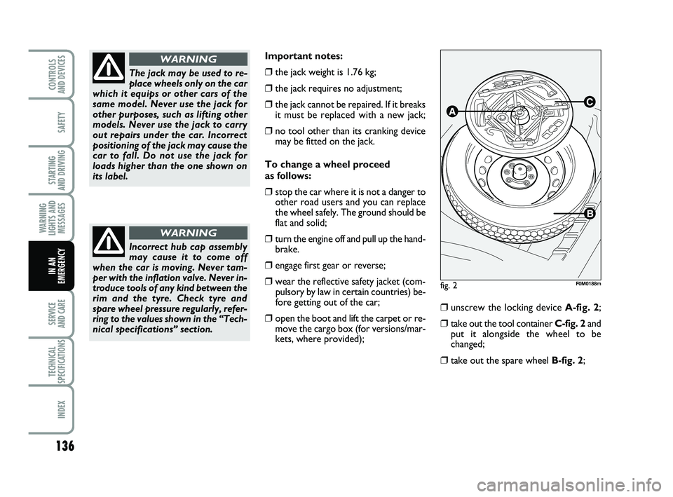
❒unscrew the locking device A-fig. 2;
❒take out the tool container C-fig. 2 and
put it alongside the wheel to be
changed;
❒take out the spare wheel B-fig. 2;
fig. 2F0M0188m
The jack may be used to re-
place wheels only on the car
which it equips or other cars of the
same model. Never use the jack for
other purposes, such as lifting other
models. Never use the jack to carry
out repairs under the car. Incorrect
positioning of the jack may cause the
car to fall. Do not use the jack for
loads higher than the one shown on
its label.
WARNING
Incorrect hub cap assembly
may cause it to come off
when the car is moving. Never tam-
per with the inflation valve. Never in-
troduce tools of any kind between the
rim and the tyre. Check tyre and
spare wheel pressure regularly, refer-
ring to the values shown in the “Tech-
nical specifications” section.
WARNING
133-164 PUNTO POP 1ed EN 24/03/14 13:05 Pagina 136
Page 146 of 219
142
SAFETY
STARTING
AND DRIVING
WARNING
LIGHTS AND MESSAGES
SERVICE
AND CARE
TECHNICAL
SPECIFICATIONS
INDEX
CONTROLS
AND DEVICES
IN AN
EMERGENCY
INFLATION PROCEDURE
The cylinder contains ethyl-
ene glycol. It contains latex,
which may cause an allergic reaction.
Harmful if swallowed. Irritates the
eyes. There could be a reaction in
case of inhalation or contact. Avoid
contact with your eyes, skin and
clothes. In the event of contact, wash
immediately with plenty of water. Do
not induce vomiting if swallowed.
Rinse your mouth out and drink plen-
ty of water. Call a doctor immedi-
ately. Keep out of the reach of chil-
dren. The product must not be used
by asthmatics. Do not breathe in the
vapours during insertion and suction.
Call a doctor immediately if allergic
reactions are noted. Store the cylin-
der in its proper compartment, away
from sources of heat. The sealant flu-
id has an expiry date.
WARNINGReplace the cylinder contain-
ing out-of-date sealant fluid.
Dispose of the cylinder and
the sealant liquid properly.
Dispose according to the national and
local laws in force.
Put on the protective gloves
provided with the quick tyre
repair kit.
WARNING
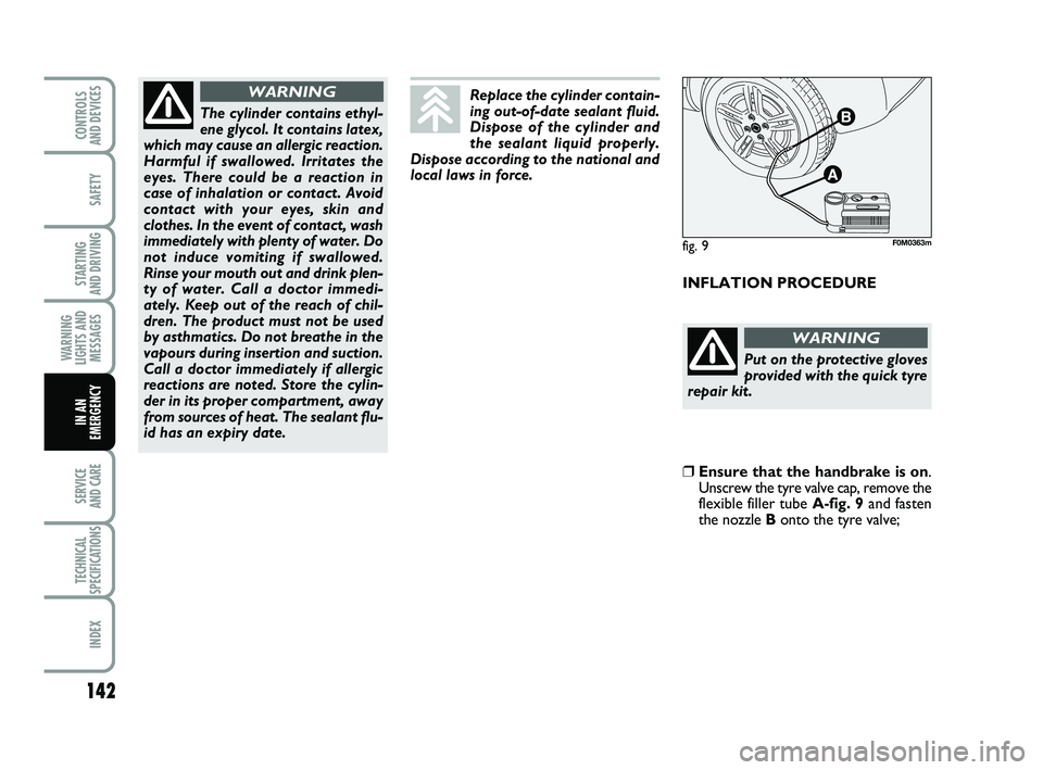
❒Ensure that the handbrake is on .
Unscrew the tyre valve cap, remove the
flexible filler tube A-fig. 9and fasten
the nozzle B onto the tyre valve;
fig. 9F0M0363m
133-164 PUNTO POP 1ed EN 24/03/14 13:05 Pagina 142
Page 147 of 219
143
SAFETY
STARTING
AND DRIVING
WARNING
LIGHTS AND MESSAGES
SERVICE
AND CARE
TECHNICAL
SPECIFICATIONS
INDEX
CONTROLS
AND DEVICES
IN AN
EMERGENCY
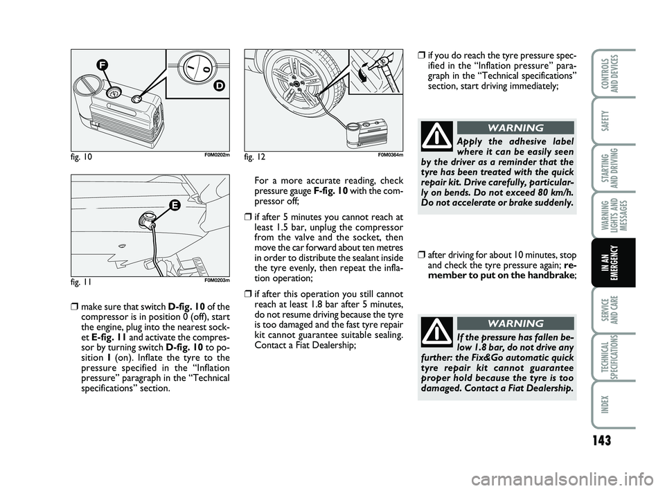
❒ make sure that switch D-fig. 10 of the
compressor is in position 0 (off), start
the engine, plug into the nearest sock-
et E-fig. 11 and activate the compres-
sor by turning switch D-fig. 10to po-
sition I(on). Inflate the tyre to the
pressure specified in the “Inflation
pressure” paragraph in the “Technical
specifications” section. For a more accurate reading, check
pressure gauge F-fig. 10
with the com-
pressor off;
❒if after 5 minutes you cannot reach at least 1.5 bar, unplug the compressor
from the valve and the socket, then
move the car forward about ten metres
in order to distribute the sealant inside
the tyre evenly, then repeat the infla-
tion operation;
❒if after this operation you still cannotreach at least 1.8 bar after 5 minutes,
do not resume driving because the tyre
is too damaged and the fast tyre repair
kit cannot guarantee suitable sealing.
Contact a Fiat Dealership;
❒if you do reach the tyre pressure spec-ified in the “Inflation pressure” para-
graph in the “Technical specifications”
section, start driving immediately;
fig. 10F0M0202m
fig. 11F0M0203m
fig. 12F0M0364m
Apply the adhesive label
where it can be easily seen
by the driver as a reminder that the
tyre has been treated with the quick
repair kit. Drive carefully, particular-
ly on bends. Do not exceed 80 km/h.
Do not accelerate or brake suddenly.
WARNING
❒after driving for about 10 minutes, stop and check the tyre pressure again; re-
member to put on the handbrake ;
If the pressure has fallen be-
low 1.8 bar, do not drive any
further: the Fix&Go automatic quick
tyre repair kit cannot guarantee
proper hold because the tyre is too
damaged. Contact a Fiat Dealership.
WARNING
133-164 PUNTO POP 1ed EN 24/03/14 13:05 Pagina 143
Page 148 of 219
144
SAFETY
STARTING
AND DRIVING
WARNING
LIGHTS AND MESSAGES
SERVICE
AND CARE
TECHNICAL
SPECIFICATIONS
INDEX
CONTROLS
AND DEVICES
IN AN
EMERGENCY
❒if you get a pressure reading of at least 1.8 bar, restore the proper pressure
(with engine running and handbrake on)
and restart;
❒drive with the utmost care to the near-est Fiat Dealership.
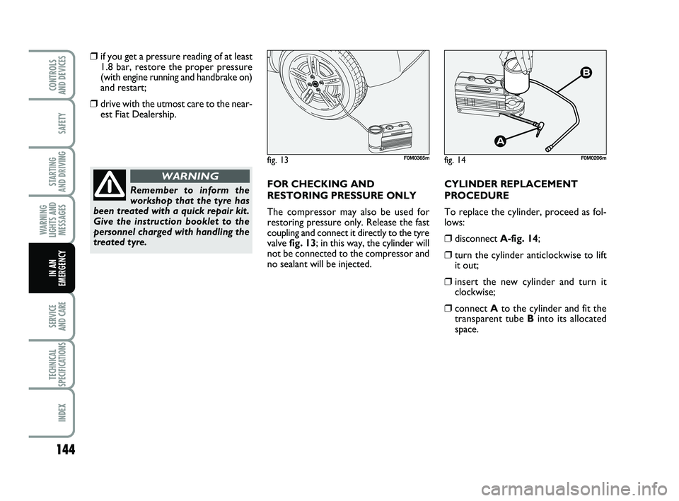
FOR CHECKING AND
RESTORING PRESSURE ONLY
The compressor may also be used for
restoring pressure only. Release the fast
coupling and connect it directly to the tyre
valve fig. 13; in this way, the cylinder will
not be connected to the compressor and
no sealant will be injected. CYLINDER REPLACEMENT
PROCEDURE
To replace the cylinder, proceed as fol-
lows:
❒disconnect
A-fig. 14;
❒turn the cylinder anticlockwise to lift
it out;
❒insert the new cylinder and turn itclockwise;
❒connect Ato the cylinder and fit the
transparent tube Binto its allocated
space.
Remember to inform the
workshop that the tyre has
been treated with a quick repair kit.
Give the instruction booklet to the
personnel charged with handling the
treated tyre.
WARNING
fig. 13F0M0365mfig. 14F0M0206m
133-164 PUNTO POP 1ed EN 24/03/14 13:05 Pagina 144
Page 150 of 219
146
SAFETY
STARTING
AND DRIVING
WARNING
LIGHTS AND MESSAGES
SERVICE
AND CARE
TECHNICAL
SPECIFICATIONS
INDEX
CONTROLS
AND DEVICES
IN AN
EMERGENCY
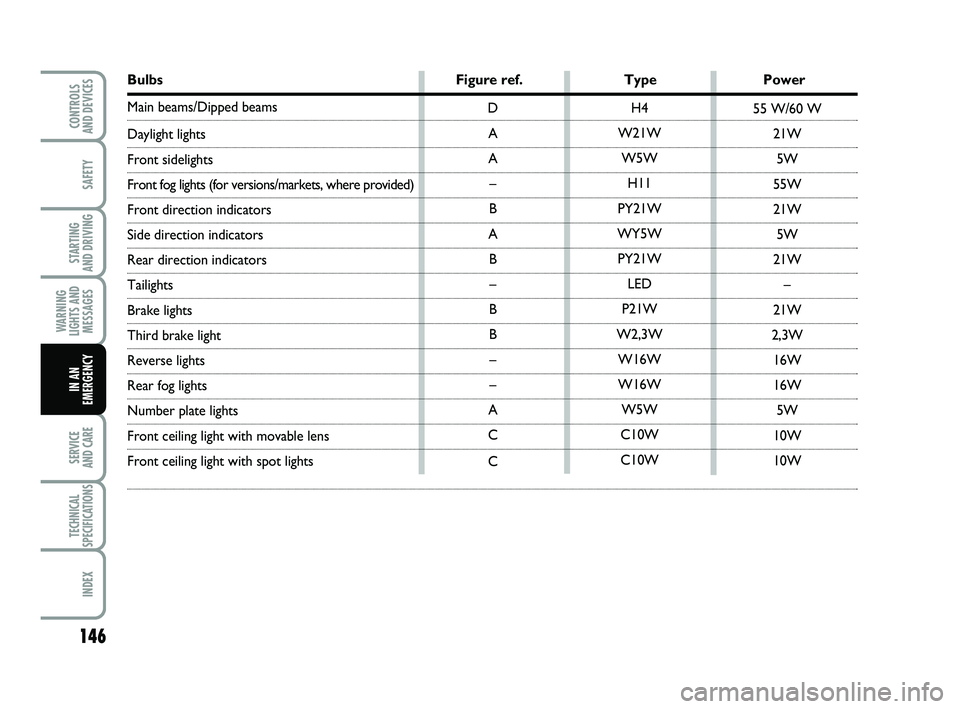
Bulbs Figure ref. TypePower
Main beams/Dipped beams
Daylight lights
Front sidelights
Front fog lights (for versions/markets, where provided)
Front direction indicators
Side direction indicators
Rear direction indicators
Tailights
Brake lights
Third brake light
Reverse lights
Rear fog lights
Number plate lights
Front ceiling light with movable lens
Front ceiling light with spot lights
H4
W21W W5W H11
PY21W
WY5W PY21W LED
P21W
W2,3W W16W
W16W W5W
C10W
C10W
D
A
A –
B
A B–
B
B –
–
A
C
C 55 W/60 W
21W5W
55W
21W 5W
21W –
21W
2,3W 16W
16W 5W
10W
10W
133-164 PUNTO POP 1ed EN 24/03/14 13:05 Pagina 146
Page 154 of 219
150
SAFETY
STARTING
AND DRIVING
WARNING
LIGHTS AND MESSAGES
SERVICE
AND CARE
TECHNICAL
SPECIFICATIONS
INDEX
CONTROLS
AND DEVICES
IN AN
EMERGENCY
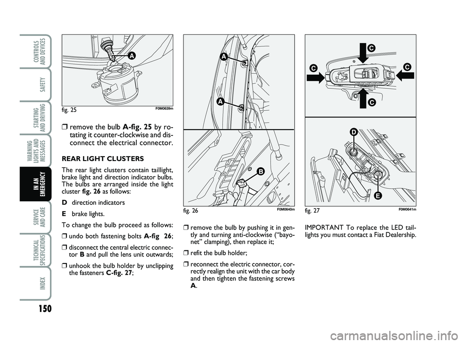
❒remove the bulb A-fig. 25 by ro-
tating it counter-clockwise and dis-
connect the electrical connector.
REAR LIGHT CLUSTERS
The rear light clusters contain taillight,
brake light and direction indicator bulbs.
The bulbs are arranged inside the light
cluster fig. 26 as follows:
D direction indicators
E brake lights.
To change the bulb proceed as follows:
❒undo both fastening bolts A-fig 26;
❒disconnect the central electric connec-
tor Band pull the lens unit outwards;
❒ unhook the bulb holder by unclipping
the fasteners C-fig. 27;
❒remove the bulb by pushing it in gen-
tly and turning anti-clockwise (“bayo-
net” clamping), then replace it;
❒refit the bulb holder;
❒reconnect the electric connector, cor-
rectly realign the unit with the car body
and then tighten the fastening screws
A. IMPORTANT To replace the LED tail-
lights you must contact a Fiat Dealership.
fig. 25
A
F0M0639m
fig. 26F0M0640mfig. 27F0M0641m
133-164 PUNTO POP 1ed EN 24/03/14 13:05 Pagina 150
Page 155 of 219
151
SAFETY
STARTING
AND DRIVING
WARNING
LIGHTS AND MESSAGES
SERVICE
AND CARE
TECHNICAL
SPECIFICATIONS
INDEX
CONTROLS
AND DEVICES
IN AN
EMERGENCY
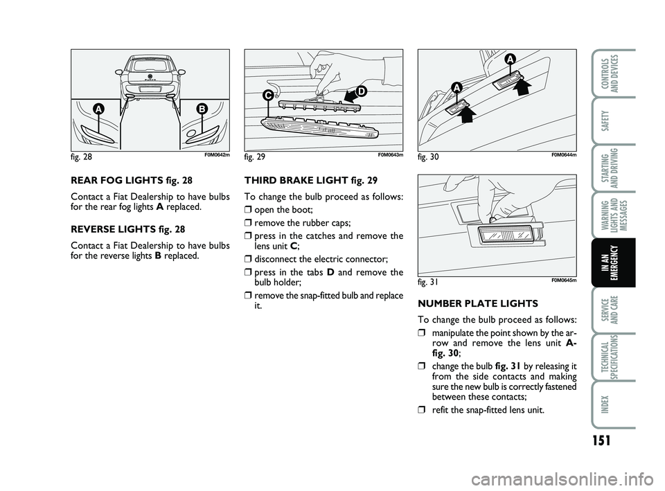
REAR FOG LIGHTS fig. 28
Contact a Fiat Dealership to have bulbs
for the rear fog lights Areplaced.
REVERSE LIGHTS fig. 28
Contact a Fiat Dealership to have bulbs
for the reverse lights B replaced.THIRD BRAKE LIGHT fig. 29
To change the bulb proceed as follows:
❒open the boot;
❒remove the rubber caps;
❒press in the catches and remove the
lens unit
C;
❒disconnect the electric connector;
❒press in the tabs Dand remove the
bulb holder;
❒remove the snap-fitted bulb and replace
it. NUMBER PLATE LIGHTS
To change the bulb proceed as follows:
❒manipulate the point shown by the ar-
row and remove the lens unit
A-
fig. 30;
❒change the bulb fig. 31 by releasing it
from the side contacts and making
sure the new bulb is correctly fastened
between these contacts;
❒refit the snap-fitted lens unit.
fig. 28F0M0642mfig. 29F0M0643mfig. 30F0M0644m
fig. 31F0M0645m
133-164 PUNTO POP 1ed EN 24/03/14 13:05 Pagina 151
Page 161 of 219
157
SAFETY
STARTING
AND DRIVING
WARNING
LIGHTS AND MESSAGES
SERVICE
AND CARE
TECHNICAL
SPECIFICATIONS
INDEX
CONTROLS
AND DEVICES
IN AN
EMERGENCY
1 (*)
8 (*)
8
13
2 (*)
5
11 4
6
14 7
12 3
10 7,5
7,5
5
5
5
10 5
20
20
20
20 5
5
7,5
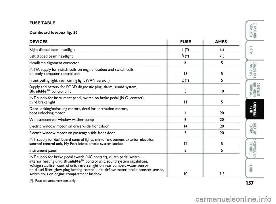
FUSE TABLE
Dashboard fusebox fig. 36
DEVICES
FUSE AMPS
Right dipped beam headlight
Left dipped beam headlight
Headlamp alignment corrector
INT/A supply for switch coils on engine fusebox and switch coils
on body computer control unit
Front ceiling light, rear ceiling light (VAN version)
Supply and battery for EOBD diagnostic plug, alarm, sound system,
Blue&Me™control unit
INT supply for instrument panel, switch on brake pedal (N.O. contact),\
third brake light
Door locking/unlocking motors, dead lock activation motors,
boot unlocking motor
Windscreen/rear window washer pump
Electric window motor on driver-side front door
Electric window motor on passenger-side front door
INT supply for dashboard control lights, mirror movement exterior electr\
ics,
sunroof control unit, My Port infotelematic system socket
Instrument panel
INT supply for brake pedal switch (NC contact), clutch pedal switch,
interior heating unit, Blue&Me™control unit, sound system capabilities,
voltage stabiliser control unit, reverse light on rear bumper, water sen\
sor
on diesel filter, glow plug heating control unit, airflow meter, brake b\
ooster sensor,
switch coils on engine compartment fusebox
(*) Fuse on some versions only.
133-164 PUNTO POP 1ed EN 24/03/14 13:05 Pagina 157