tow FIAT PUNTO 2021 Owner handbook (in English)
[x] Cancel search | Manufacturer: FIAT, Model Year: 2021, Model line: PUNTO, Model: FIAT PUNTO 2021Pages: 219, PDF Size: 9.82 MB
Page 120 of 219
116
SAFETY
WARNING
LIGHTS AND MESSAGES
IN AN
EMERGENCY
SERVICE
AND CARE
TECHNICAL
SPECIFICATIONS
INDEX
CONTROLS
AND DEVICES
STARTING
AND DRIVING
DRIVING STYLE
Starting
Do not warm up the engine at low or high
revs when the vehicle is stationary; this
causes the engine to warm up more slow-
ly, thereby increasing fuel consumption
and emissions. It is advisable to set off im-
mediately and slowly, avoiding high revs:
this allows the engine to warm up more
quickly.
Unnecessary actions
Avoid revving up when stationary at traf-
fic lights or before stopping the engine.
The latter action, like double declutching,
is entirely unnecessary and causes in-
creased fuel consumption and pollution.
Gear selection
Use a higher gear as soon as traffic and
road conditions allow. Using a low gear
for faster acceleration will increase fuel
consumption.
In the same way, improper use of a high
gear increases fuel consumption, emissions
and engine wear. Traffic and road conditions
Heavy traffic, for instance when travelling
in a queue with frequent use of low gears
or in cities with lots of traffic lights, caus-
es fairly high fuel consumption. Mountain
roads and uneven surfaces also have a neg-
ative effect on consumption.
Traffic hold-ups
During prolonged hold-ups (e.g. at level
crossings) the engine should be switched
off.
TOWING TRAILERS
IMPORTANT NOTES
The car must be equipped with an ap-
proved tow hook and adequate electrical
system to tow caravans or trailers. Instal-
lation must be performed by specialised
personnel who will issue the required pa-
pers for travelling on roads.
Install any specific and/or additional rear
view mirrors in accordance with the high-
way code of the country in which you are
travelling.
Top speed
Fuel consumption considerably increases
as speed increases. Keep your speed as
even as possible, avoiding unnecessary
braking and acceleration, which cause ex-
cessive fuel consumption and increased
emissions.
Acceleration
Accelerating violently severely affects con-
sumption and emissions: acceleration
should be gradual and should not exceed
the maximum torque.
CONDITIONS OF USE
Cold starting
Short distances and frequent cold start-
ups will prevent the engine from reach-
ing optimal running temperature. Conse-
quently, both fuel consumption (from +15
to +30% on the urban cycle) and emis-
sions will increase.
111-120 PUNTO POP 1ed EN 24/09/13 14.29 Pagina 116
Page 121 of 219
117
SAFETY
WARNING
LIGHTS AND MESSAGES
IN AN
EMERGENCY
SERVICE
AND CARE
TECHNICAL
SPECIFICATIONS
INDEX
CONTROLS
AND DEVICES
STARTING
AND DRIVING
Remember that, when towing a trailer,
steep hills are harder to climb, braking dis-
tances increase and overtaking takes
longer relative to the overall weight of the
trailer.
Engage a low gear when driving downhill,
rather than constantly using the brake.
The weight of the trailer on the car’s tow
hook will reduce the load capacity of the
car by the same amount. Consider the
weight of the trailer fully laden, including
accessories and luggage, to make sure you
do not exceed the maximum towable
weight (shown on the vehicle registration
document).
Respect each country’s specific speed lim-
its for vehicles towing trailers. The top
speed must not exceed 100 km/h at any
time.
You should fit a suitable stabiliser to the
trailer.
The ABS with which the car
may be equipped will not
control the braking system of the
trailer. Particular caution is therefore
required on slippery roads.
WARNING
Never modify the braking
system of the car to control
the trailer brake. The trailer braking
system must be fully independent
from the hydraulic system of the car.
WARNING
INSTALLING THE TOW HOOK
The towing device should be fastened to
the body by specialised personnel in ac-
cordance with any additional information
supplied by the manufacturer of the device.
The towing device must meet current reg-
ulations with reference to Directive
94/20/EC and subsequent amendments.
For any version the towing device used
must be right for the towable weight of
the car on which it is to be installed.
For the electric connection a unified con-
nector should be used, which is generally
placed on a special bracket fastened to the
towing device, and a special ECU should
be installed on the car to control the trail-
er’s exterior lights.
Seven- or 13-pin 12VDC connections
should be used (CUNA/UNI and ISO/DIN
Standards). Follow any instructions pro-
vided by the car manufacturer and/or the
towing device manufacturer. An electric brake or winch should be pow-
ered directly by the battery through a ca-
ble with a cross-section of no less than
2.5 mm
2.
IMPORTANT The engine must be running
to use the electric brake or winch.
In addition to the electrical appliances, the
car’s electrical system may be connected
only to the supply cable for an electric
brake and the cable for a light inside the
trailer with a wattage of no more than
15 W.
For connections, use the preset control
unit with a battery cable no less than
2.5 mm
2.
111-120 PUNTO POP 1ed EN 24/09/13 14.29 Pagina 117
Page 122 of 219
118
SAFETY
WARNING
LIGHTS AND MESSAGES
IN AN
EMERGENCY
SERVICE
AND CARE
TECHNICAL
SPECIFICATIONS
INDEX
CONTROLS
AND DEVICES
STARTING
AND DRIVING
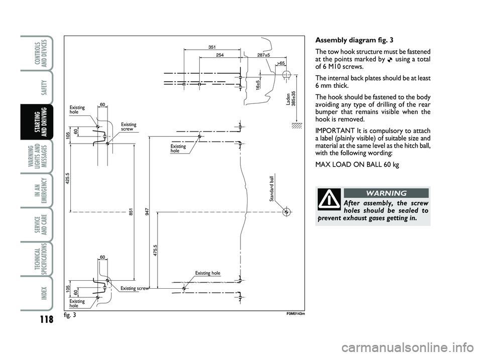
Assembly diagram fig. 3
The tow hook structure must be fastened
at the points marked by
Øusing a total
of 6 M10 screws.
The internal back plates should be at least
6 mm thick.
The hook should be fastened to the body
avoiding any type of drilling of the rear
bumper that remains visible when the
hook is removed.
IMPORTANT It is compulsory to attach
a label (plainly visible) of suitable size and
material at the same level as the hitch ball,
with the following wording:
MAX LOAD ON BALL 60 kg
After assembly, the screw
holes should be sealed to
prevent exhaust gases getting in.
WARNING
fig. 3F0M0143m
Existing
hole
Existing
screw
Existing screw
Existing
hole Existing
hole
Existing hole
Standard ball Laden
111-120 PUNTO POP 1ed EN 24/09/13 14.29 Pagina 118
Page 128 of 219
124
SAFETY
STARTING
AND DRIVING
IN AN
EMERGENCY
SERVICE
AND CARE
TECHNICAL
SPECIFICATIONS
INDEX
CONTROLS
AND DEVICES
WARNING
LIGHTS AND MESSAGES
LOW ENGINE OIL
PRESSURE (red)
EXHAUSTED ENGINE
OIL
(only Multijet versions with
DPF - red)
When the ignition key is turned to MAR
(ON), the warning light switches on and
should go out as soon as the engine is
started.
Low engine oil pressure
The warning light turns on and stays on
constantly (for versions/markets, where
provided) along with the message on the
display when the system detects that en-
gine oil pressure is low.
v
If the warning light vturns on when the vehicle is
travelling (on certain versions to-
gether with the message on the dis-
play) stop the engine immediately
and contact a Fiat Dealership.
WARNING
❒ if the vehicle is used under de-
manding conditions (e.g. towing
trailers uphill or fully loaded): slow
down and, if the light stays on, stop the
car. Stop for 2 or 3 minutes with the
engine running and slightly accelerated
to assist better coolant circulation.
Then switch the engine off. Check cor-
rect fluid level as described above.
IMPORTANT On particularly demanding
journeys, it is advisable to keep the engine
on and slightly accelerated for a few min-
utes before switching it off.
A specific message is displayed on certain
versions.
LOW BATTERY
CHARGE (red)
When the ignition key is moved to MAR,
the warning light turns on but should go
out as soon as the engine is started (with
the engine idling, a brief delay can be ex-
pected).
If the warning light comes on, either per-
manently or intermittently, contact a Fiat
Dealership immediately.
w
Exhausted engine oil
(only Multijet versions with DPF)
The warning light will flash and a specific
message will appear on the display (for
versions/markets, where provided). The
warning light may flash in the following
ways, depending on the version:
– for 1 minute every two hours;
– for 3 minute cycles with the warning
light off for intervals of 5 seconds until oil
is changed.
After the initial warning, each time the en-
gine is started up, the warning light will
continue to flash in the above mentioned
modes, until the oil is changed. A specific
message will appear on the display (for
versions/markets, where provided) in ad-
dition to the warning light.
If the warning light flashes, this does not
mean that the car is defective but simply
informs the driver that it is now necessary
to change the oil as a result of regular ve-
hicle use.
Note that engine oil is exhausted faster
under the following circumstances:
– use of the vehicle prevalently for city dri-
ving, requiring more frequent regenera-
tion of DPF
– use of the vehicle for short drives, in
which the engine does not have time to
reach its regular operating temperature
– repeated interruption of the regenera-
tion process, signalled by the DPF warn-
ing light coming on.
121-132 PUNTO POP 1ed EN 29/08/13 15.03 Pagina 124
Page 137 of 219
133
SAFETY
STARTING
AND DRIVING
WARNING
LIGHTS AND MESSAGES
SERVICE
AND CARE
TECHNICAL
SPECIFICATIONS
INDEX
CONTROLS
AND DEVICES
IN AN
EMERGENCY
STARTING THE ENGINE ................................................. 134
CHANGING A TYRE ......................................................... 135
QUICK TYRE REPAIR KIT FIX&GO AUTOMATIC ... 140
CHANGING A BULB ......................................................... 145
CHANGING AN EXTE RIOR BULB ................................ 147
CHANGING AN INTE RIOR BULB ................................ 152
CHANGING A FUSE .......................................................... 153
RECHARGING THE BATTE RY ....................................... 161
RAISING THE CAR ............................................................. 162
TOWING THE CAR ........................................................... 163
I
I
N
N
A
A
N
N
E
E
M
M
E
E
R
R
G
G
E
E
N
N
C
C
Y
Y
In an emergency we recommend that you call the toll-free number found in\
the Warranty Booklet.
You can also go to the www.fiat.com website to find your nearest Fiat De\
alership.
133-164 PUNTO POP 1ed EN 24/03/14 13:05 Pagina 133
Page 139 of 219
135
SAFETY
STARTING
AND DRIVING
WARNING
LIGHTS AND MESSAGES
SERVICE
AND CARE
TECHNICAL
SPECIFICATIONS
INDEX
CONTROLS
AND DEVICES
IN AN
EMERGENCY
CHANGING A TYRE
GENERAL INSTRUCTIONS
Wheel changing and correct use of the
jack and spare wheel call for some pre-
cautions, as listed below.
Use your hazard lights,
warning triangle, etc to show
that your car is stationary. Passengers
should get out of the car, particular-
ly if it is heavily loaded, and wait for
the wheel to be changed away from
the traffic. Apply the handbrake.
WARNING
The spare wheel provided is
specific for your vehicle.
Therefore, it must not be used on dif-
ferent models and you should not use
spare wheels from other models on
your vehicle. The wheel bolts are spe-
cific for your vehicle: do not use them
on different models and do not use
bolts from other models on your car.
WARNING
Repair and refit the standard
wheel as soon as possible.
Do not apply grease to the bolt
threads before assembly: they might
spontaneously unscrew.
WARNING
BUMP STARTING
Never bump start the engine by pushing,
towing or driving downhill. This could
cause fuel to flow into the catalytic con-
verter and damage it beyond repair.
IMPORTANT Remember that the brake
booster and the power steering system
are not active until the engine is started,
so you will need to apply much more force
to the brake pedal or steering wheel.
133-164 PUNTO POP 1ed EN 24/03/14 13:05 Pagina 135
Page 143 of 219
139
SAFETY
STARTING
AND DRIVING
WARNING
LIGHTS AND MESSAGES
SERVICE
AND CARE
TECHNICAL
SPECIFICATIONS
INDEX
CONTROLS
AND DEVICES
IN AN
EMERGENCY
Versions with steel rims
Proceed as follows:
❒make sure the contact surfaces be- tween standard wheel and hub are
clean so that the fastening bolts will not
come loose;
❒fit the standard wheel by inserting thefirst bolt two threads into the hole clos-
est to the inflation valve;
❒fit the hub cap by aligning the crescenthole with the bolt you have fitted, then
insert the other 3 bolts;
❒using the wrench provided, tighten thefastening bolts;
❒lower the car and remove the jack;
❒using the wrench provided, fully tight-en the bolts in the sequence shown
previously. Versions with alloy rims
Proceed as follows:
❒place the wheel onto the hub and tight-
en the bolts using the wrench provided;
❒lower the car and remove the jack;
❒using the wrench provided, fully tight-
en the bolts in the sequence shown
previously. When you have finished
❒stow the spare wheel in the space pro-
vided in the boot;
❒put the jack back in its container C-
fig. 2
partially open by forcing it slight-
ly against the container walls to prevent
it from rattling around when travelling;
❒put the tools back into their places in
the container;
❒stow the container C-fig. 2, complete
with tools, inside the spare wheel;
❒tighten the tool container clamping de-
vice A-fig. 2;
❒refit the boot carpet or the Cargo box
(for versions/markets, where provid-
ed).
133-164 PUNTO POP 1ed EN 24/03/14 13:05 Pagina 139
Page 144 of 219
140
SAFETY
STARTING
AND DRIVING
WARNING
LIGHTS AND MESSAGES
SERVICE
AND CARE
TECHNICAL
SPECIFICATIONS
INDEX
CONTROLS
AND DEVICES
IN AN
EMERGENCY
QUICK TYRE REPAIR KIT
FIX&GO automatic
(for versions/markets, where provided)
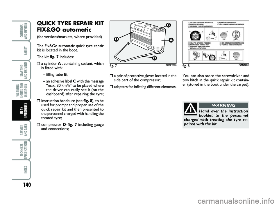
The Fix&Go automatic quick tyre repair
kit is located in the boot.
The kit fig. 7 includes:
❒a cylinder A , containing sealant, which
is fitted with:
– filling tube B;
– an adhesive label C with the message
“max. 80 km/h” to be placed where
the driver can easily see it (on the
dashboard) after repairing the tyre;
❒instruction brochure (see fig. 8), to be used for prompt and proper use of the
quick repair kit and then presented to
the personnel charged with handling the
treated tyre;
❒compressor D-fig. 7including gauge
and connections;
❒a pair of protective gloves located in the side part of the compressor;
❒adapters for inflating different elements.
fig. 7F0M0198m
You can also store the screwdriver and
tow hitch in the quick repair kit contain-
er (stored in the boot under the carpet).
fig. 8F0M0199m
Hand over the instruction
booklet to the personnel
charged with treating the tyre re-
paired with the kit.
WARNING
133-164 PUNTO POP 1ed EN 24/03/14 13:05 Pagina 140
Page 153 of 219
149
SAFETY
STARTING
AND DRIVING
WARNING
LIGHTS AND MESSAGES
SERVICE
AND CARE
TECHNICAL
SPECIFICATIONS
INDEX
CONTROLS
AND DEVICES
IN AN
EMERGENCY
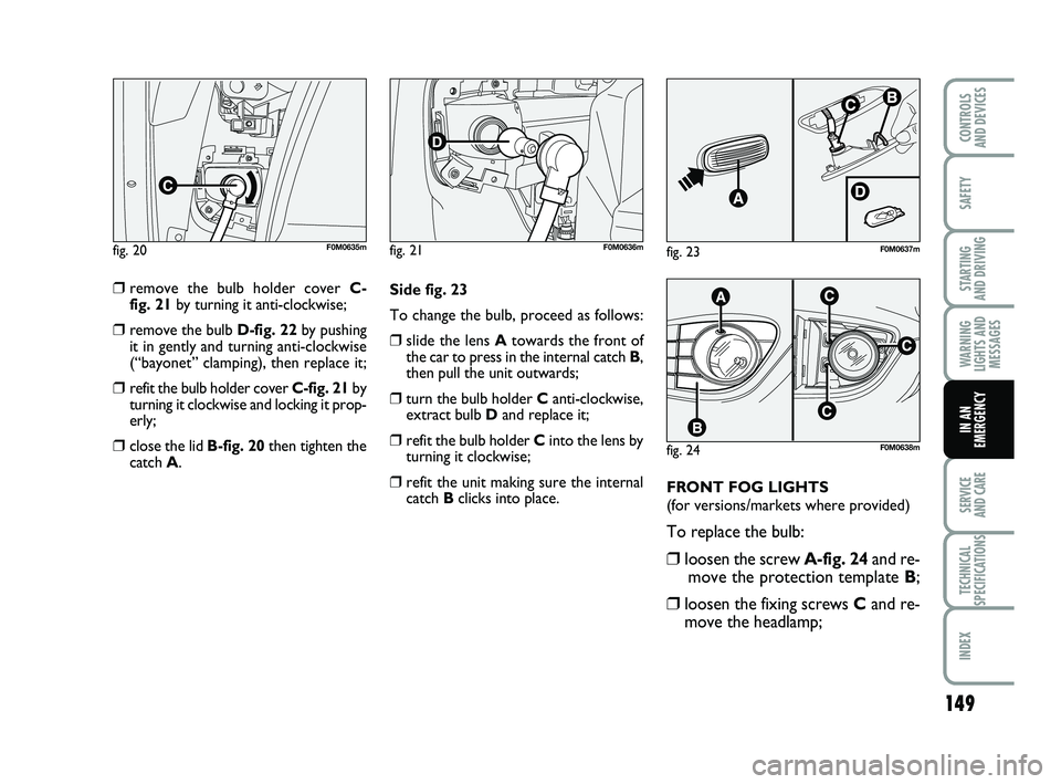
❒remove the bulb holder cover C-
fig. 21 by turning it anti-clockwise;
❒remove the bulb D-fig. 22 by pushing
it in gently and turning anti-clockwise
(“bayonet” clamping), then replace it;
❒refit the bulb holder cover C-fig. 21 by
turning it clockwise and locking it prop-
erly;
❒close the lid B-fig. 20 then tighten the
catch A. Side fig. 23
To change the bulb, proceed as follows:
❒slide the lens A
towards the front of
the car to press in the internal catch B,
then pull the unit outwards;
❒turn the bulb holder C anti-clockwise,
extract bulb D and replace it;
❒refit the bulb holder C into the lens by
turning it clockwise;
❒refit the unit making sure the internal
catch Bclicks into place. FRONT FOG LIGHTS
(for versions/markets where provided)
To replace the bulb:
❒loosen the screw A-fig. 24
and re-
move the protection template B;
❒loosen the fixing screws Cand re-
move the headlamp;
fig. 20F0M0635mfig. 21F0M0636m
fig. 24F0M0638m
fig. 23F0M0637m
133-164 PUNTO POP 1ed EN 24/03/14 13:05 Pagina 149
Page 164 of 219
160
SAFETY
STARTING
AND DRIVING
WARNING
LIGHTS AND MESSAGES
SERVICE
AND CARE
TECHNICAL
SPECIFICATIONS
INDEX
CONTROLS
AND DEVICES
IN AN
EMERGENCY
17
14
01
03
04
15
10
16
08
07
05
11
13
09
06
0220
7,5 –
–
–
–
20 –
10 –
15
20 –
10 –
–
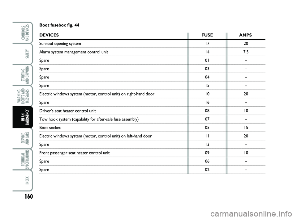
Boot fusebox fig. 44
DEVICES
FUSE AMPS
Sunroof opening system
Alarm system management control unit
Spare
Spare
Spare
Spare
Electric windows system (motor, control unit) on right-hand door
Spare
Driver’s seat heater control unit
Tow hook system (capability for after-sale fuse assembly)
Boot socket
Electric windows system (motor, control unit) on left-hand door
Spare
Front passenger seat heater control unit
Spare
Spare
133-164 PUNTO POP 1ed EN 24/03/14 13:05 Pagina 160