engine FIAT QUBO 2010 1.G User Guide
[x] Cancel search | Manufacturer: FIAT, Model Year: 2010, Model line: QUBO, Model: FIAT QUBO 2010 1.GPages: 230, PDF Size: 4.38 MB
Page 27 of 230
TRIP COMPUTER
General features
The Trip computer is used to display information on
vehicle operation when the ignition key is turned
to MAR. This function allows you to define two
separate trips, called "Trip A" and "Trip B", for
monitoring the "complete mission" (journey) of the
vehicle in a reciprocally independent manner. Both
functions can be reset (start of a new journey).
“Trip A” is used to display the values relating to:
❒Outside temperature (for versions with outside
temperature sensor and methane-powered
vehicles)
❒Range
❒Distance travelled
❒Average consumption
❒Current consumption
❒Average speed
❒Travel time (driving time).
"Trip B", available on multifunction display only, is
used to display the values relating to:
❒Distance travelled B
❒Average consumption B
❒Average speed B
❒Travel time B (driving time).
“Trip B” may be disabled (see “Activating
Trip B”). “Range” and “Instant
consumption" parameters cannot be
reset .
Values displayed
Range
This indicates the distance which may be travelled
with the fuel in the tank assuming that driving style
does not change. The display will show the reading
“----“ when the following events take place:
❒range is lower than 50 km (or 30 mi)
❒vehicle is left parked with the engine running for a
long time.
IMPORTANT The range can be affected by several
factors: driving style (see “Driving style” in the
“Starting and driving” section), type of route
(motorway, towns and cities, mountain roads, etc.),
conditions of use (load, tyre pressures, etc.). Trip
planning must therefore take the above into account.
Distance travelled
This value shows the distance covered from the start
of the new journey.
26
KNOW YOUR
VEHICLE
SAFETY
ST
ARTING AND
DRIVING
WARNING LIGHTS
AND MESSAGES
IN AN EMERGENCY
SERVICING AND
MAINTENANCE
TECHNICAL
SPECIFICATIONS
INDEX
Page 28 of 230
Average consumption
This value shows the approximate average fuel
consumption from the start of the new journey.
Current consumption
Indicates the fuel consumption. The value is
constantly updated. The message “----” will appear
on the display if the car is parked with the engine
running.
Average speed
This value shows the average speed of the vehicle
based on the overall time elapsed since the start of
the new journey.
Journey time
Time elapsed since the start of the new journey.
IMPORTANT If there is no information, the Trip
computer displays "----" in place of the value. When
normal operating conditions are restored, the
counting of the various values is resumed, without
either zeroing the values displayed prior to the
problem, or starting a new journey.Control TRIP button
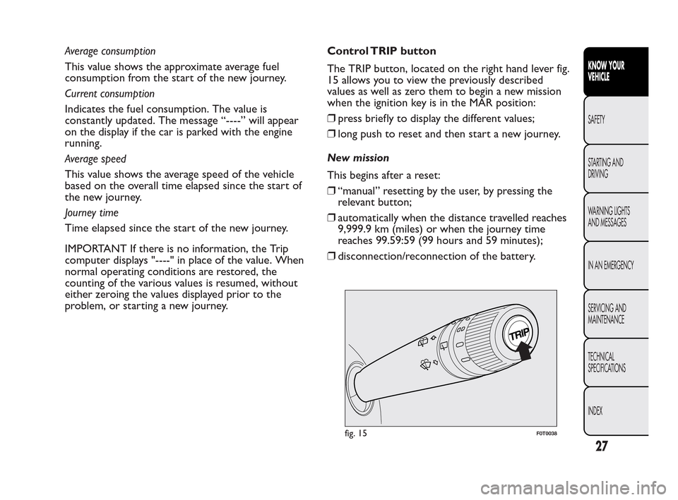
The TRIP button, located on the right hand lever fig.
15 allows you to view the previously described
values as well as zero them to begin a new mission
when the ignition key is in the MAR position:
❒press briefly to display the different values;
❒long push to reset and then start a new journey.
New mission
This begins after a reset:
❒“manual” resetting by the user, by pressing the
relevant button;
❒automatically when the distance travelled reaches
9,999.9 km (miles) or when the journey time
reaches 99.59:59 (99 hours and 59 minutes);
❒disconnection/reconnection of the battery.
fig. 15F0T0038
27
KNOW YOUR
VEHICLE
SAFETY
ST
ARTING AND
DRIVING
WARNING LIGHTS
AND MESSAGES
IN AN EMERGENCY
SERVICING AND
MAINTENANCE
TECHNICAL
SPECIFICATIONS
INDEX
Page 33 of 230
HEADREST
FRONT
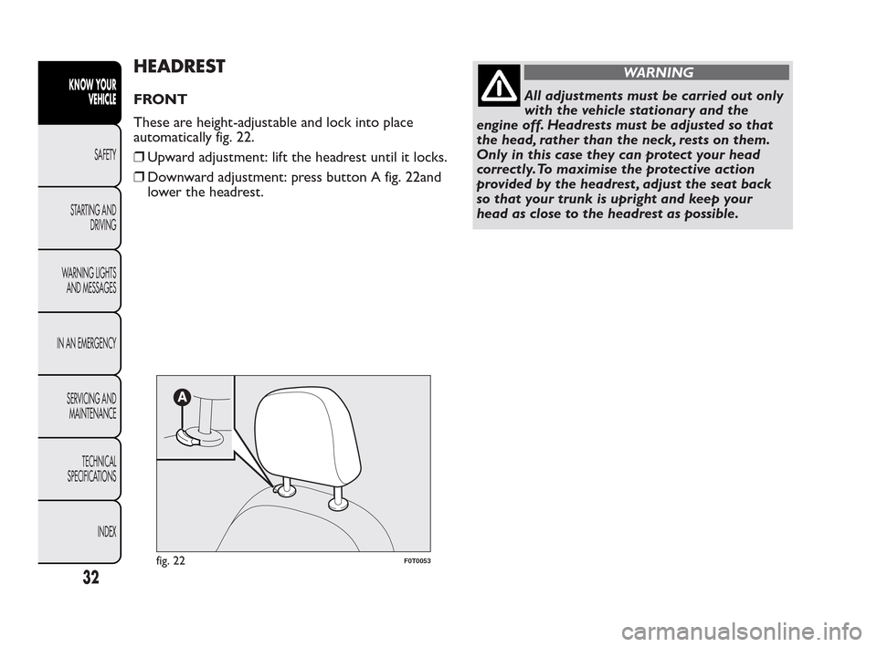
These are height-adjustable and lock into place
automatically fig. 22.
❒Upward adjustment: lift the headrest until it locks.
❒Downward adjustment: press button A fig. 22and
lower the headrest.
WARNING
All adjustments must be carried out only
wi
th the vehicle stationary and the
engine off. Headrests must be adjusted so that
the head, rather than the neck, rests on them.
Only in this case they can protect your head
correctly.To maximise the protective action
provided by the headrest , adjust the seat back
so that your trunk is upright and keep your
head as close to the headrest as possible.
fig. 22F0T0053
32
KNOW YOUR
VEHICLE
SAFETY
ST
ARTING AND
DRIVING
WARNING LIGHTS
AND MESSAGES
IN AN EMERGENCY
SERVICING AND
MAINTENANCE
TECHNICAL
SPECIFICATIONS
INDEX
Page 35 of 230
STEERING WHEEL
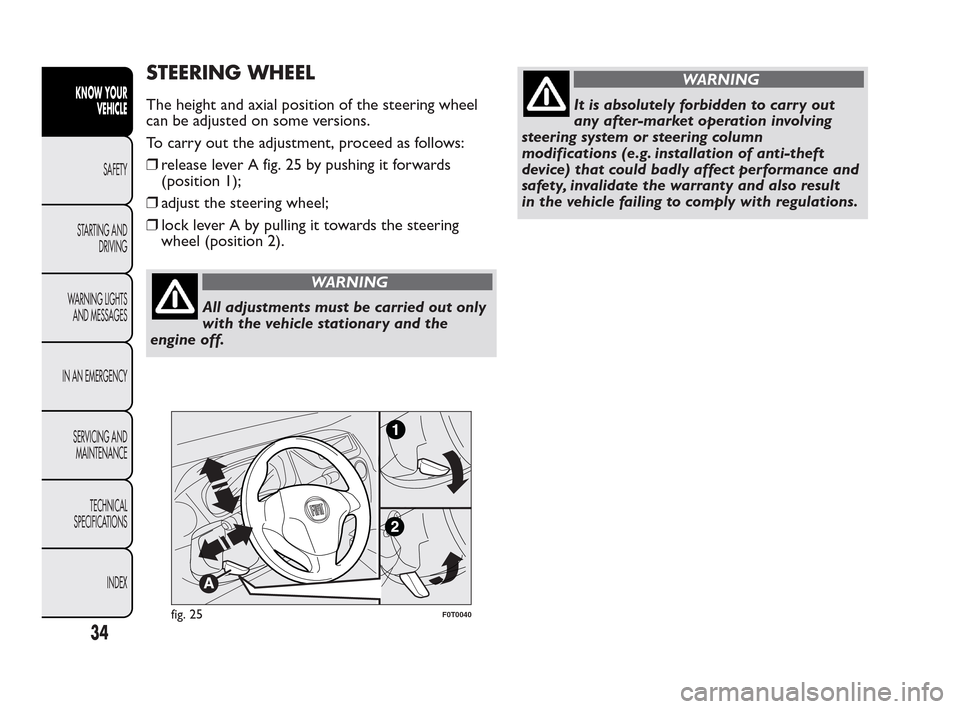
The height and axial position of the steering wheel
can be adjusted on some versions.
To carry out the adjustment, proceed as follows:
❒release lever A fig. 25 by pushing it forwards
(position 1);
❒adjust the steering wheel;
❒lock lever A by pulling it towards the steering
wheel (position 2).
WARNING
All adjustments must be carried out only
wi
th the vehicle stationary and the
engine off.
WARNING
It is absolutely forbidden to carry out
an
y after-market operation involving
steering system or steering column
modifications (e.g. installation of anti-theft
device) that could badly affect performance and
safety, invalidate the warranty and also result
in the vehicle failing to comply with regulations.
fig. 25F0T0040
34
KNOW YOUR
VEHICLE
SAFETY
ST
ARTING AND
DRIVING
WARNING LIGHTS
AND MESSAGES
IN AN EMERGENCY
SERVICING AND
MAINTENANCE
TECHNICAL
SPECIFICATIONS
INDEX
Page 48 of 230
“FOLLOW ME HOME” DEVICE
This device lights up the space in front of the vehicle
for a short time.
Activation
With the ignition key in the STOP position or
extracted, pull the stalk towards the steering wheel
and move it within 2 minutes of the engine switching
off.
Each time the stalk is moved, the lights stay on for an
extra 30 seconds up to a maximum of 210 seconds;
then the lights are switched off automatically.
Each time the stalk is moved, instrument panel
warning light
comes on and the corresponding
message will appear on the display (see “Warning
lights and messages”) for as long as the function
remains on. The light comes on when the stalk is
first moved and stays on until the function is
automatically deactivated. Each movement of the
stalk increases only the amount of time the lights
stay on.
Deactivation
Keep the stalk pulled towards the steering wheel for
more than 2 seconds.
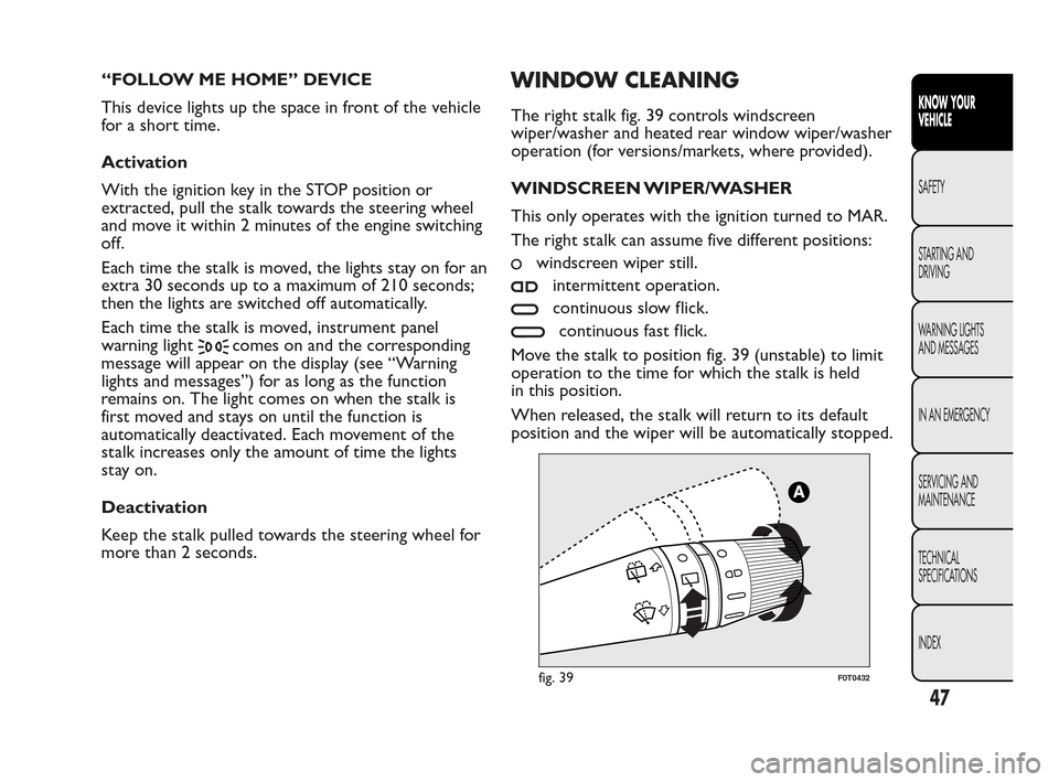
WINDOW CLEANING
The right stalk fig. 39 controls windscreen
wiper/washer and heated rear window wiper/washer
operation (for versions/markets, where provided).
WINDSCREEN WIPER/WASHER
This only operates with the ignition turned to MAR.
The right stalk can assume five different positions:
windscreen wiper still.
intermittent operation.
continuous slow flick.
continuous fast flick.
Move the stalk to position fig. 39 (unstable) to limit
operation to the time for which the stalk is held
in this position.
When released, the stalk will return to its default
position and the wiper will be automatically stopped.
fig. 39F0T0432
47
KNOW YOUR
VEHICLE
SAFETY
ST
ARTING AND
DRIVING
WARNING LIGHTS
AND MESSAGES
IN AN EMERGENCY
SERVICING AND
MAINTENANCE
TECHNICAL
SPECIFICATIONS
INDEX
Page 51 of 230
FRONT CEILING LIGHT WITH SPOT
LIGHTS
(for versions/markets, where provided)
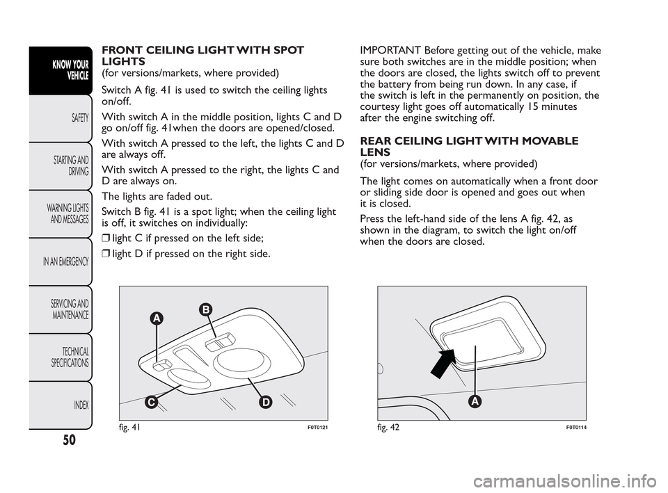
Switch A fig. 41 is used to switch the ceiling lights
on/off.
With switch A in the middle position, lights C and D
go on/off fig. 41when the doors are opened/closed.
With switch A pressed to the left, the lights C and D
arealwaysoff.
With switch A pressed to the right, the lights C and
D are always on.
The lights are faded out.
Switch B fig. 41 is a spot light; when the ceiling light
is off, it switches on individually:
❒light C if pressed on the left side;
❒light D if pressed on the right side.IMPORTANT Before getting out of the vehicle, make
sure both switches are in the middle position; when
the doors are closed, the lights switch off to prevent
the battery from being run down. In any case, if
the switch is left in the permanently on position, the
courtesy light goes off automatically 15 minutes
after the engine switching off.
REAR CEILING LIGHT WITH MOVABLE
LENS
(for versions/markets, where provided)
The light comes on automatically when a front door
or sliding side door is opened and goes out when
it is closed.
Press the left-hand side of the lens A fig. 42, as
shown in the diagram, to switch the light on/off
when the doors are closed.
fig. 41F0T0121fig. 42F0T0114
50
KNOW YOUR
VEHICLE
SAFETY
ST
ARTING AND
DRIVING
WARNING LIGHTS
AND MESSAGES
IN AN EMERGENCY
SERVICING AND
MAINTENANCE
TECHNICAL
SPECIFICATIONS
INDEX
Page 71 of 230
SECURING YOUR LOAD
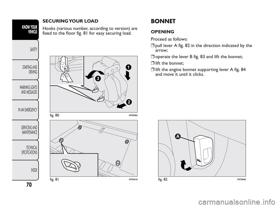
Hooks (various number, according to version) are
fixed to the floor fig. 81 for easy securing load.BONNET
OPENING
Proceed as follows:
❒pull lever A fig. 82 in the direction indicated by the
arrow;
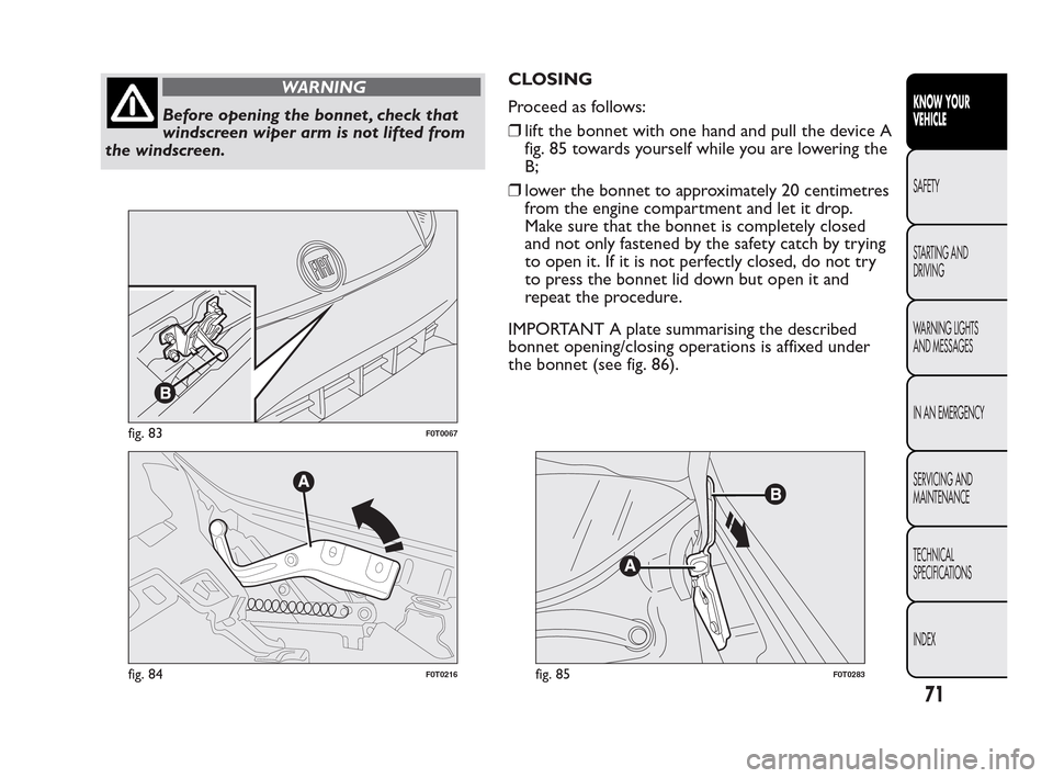
❒operate the lever B fig. 83 and lift the bonnet;
❒lift the bonnet;
❒lift the engine bonnet supporting lever A fig. 84
and move it until it clicks.
fig. 80F0T0302
fig. 81F0T0418fig. 82F0T0045
70
KNOW YOUR
VEHICLE
SAFETY
ST
ARTING AND
DRIVING
WARNING LIGHTS
AND MESSAGES
IN AN EMERGENCY
SERVICING AND
MAINTENANCE
TECHNICAL
SPECIFICATIONS
INDEX
Page 72 of 230
WARNING
Before opening the bonnet , check that
win
dscreen wiper arm is not lifted from
the windscreen.CLOSING
Proceed as follows:
❒lift the bonnet with one hand and pull the device A
fig. 85 towards yourself while you are lowering the
B;
❒lower the bonnet to approximately 20 centimetres
from the engine compartment and let it drop.
Make sure that the bonnet is completely closed
and not only fastened by the safety catch by trying
to open it. If it is not perfectly closed, do not try
to press the bonnet lid down but open it and
repeat the procedure.
IMPORTANT A plate summarising the described
bonnet opening/closing operations is affixed under
the bonnet (see fig. 86).
fig. 83F0T0067
fig. 84F0T0216fig. 85F0T0283
71
KNOW YOUR
VEHICLE
SAFETY
ST
ARTING AND
DRIVING
WARNING LIGHTS
AND MESSAGES
IN AN EMERGENCY
SERVICING AND
MAINTENANCE
TECHNICAL
SPECIFICATIONS
INDEX
Page 78 of 230
ESP SYSTEM (Electronic Stability
Program)
(for versions/markets, where provided)
This is an electronic system that controls vehicle
stability in the event of tyre grip loss, helping to
maintain directional control.
The ESP system is therefore particularly useful when
the grip conditions of road surfaces change.
The MSR system (adjustment of the engine braking
torque during gear changes) and the HBA system
(automatic increase in the braking pressure during
emergency braking) are present with ESP, ASR and
Hill Holder systems (for versions/markets where
provided).
SYSTEM INTERVENTION
It is signalled by the blinking of the instrument panel
warning light
, to inform the driver that the car
is in critical stability and grip conditions.
Switching the system on
The ESP system is automatically activated when the
vehicle is started and cannot be de-activated.Failure indications
In the event of a failure, the ESP will be automatically
switched off and the
warning light will come on
permanently on the instrument panel along with
a message on the multifunction display (for
versions/markets, where provided) (see “Warning
lights and messages” section). The LED on the ASR
OFF button will also light up. Contact a Fiat
Dealership as soon as possible.
WARNING
Do not take unnecessary risks, even if
y
our vehicle is fitted with an ESP
system.Your driving style should always take
road conditions, visibility and traffic into
account .The driver is always responsible for
road safety.
77
KNOW YOUR
VEHICLE
SAFETY
ST
ARTING AND
DRIVING
WARNING LIGHTS
AND MESSAGES
IN AN EMERGENCY
SERVICING AND
MAINTENANCE
TECHNICAL
SPECIFICATIONS
INDEX
Page 79 of 230
HILL HOLDER SYSTEM
(for versions/markets, where provided)
It's integral to the ESP system. It automatically
activates with the following conditions:
❒uphill: vehicle stationary on a road with a gradient
higher than 5%, engine running, brake pedal
pressed and gearbox in neutral or gear other than
reverse;
❒downhill: vehicle stationary on a road with a
gradient higher than 5%, engine running, brake
pedal pressed and reverse gear engaged.
At pickup the ESP system control unit will keep
brake force on wheels until reaching the torque
suitable for starting, or in any case for max. 2
seconds in order to pass easily from the brake pedal
to the accelerator pedal.
When 2 seconds have elapsed, without any
departure having taken place, the system is
automatically deactivated, gradually releasing the
braking pressure. During this release stage, the
typical brake disengagement noise indicating that the
vehicle is going to move imminently will be heard.
Failure indications
IMPORTANT The Hill Holder system is not a parking
brake; therefore, never leave the vehicle without
having engaged the handbrake, turned the engine off
and engaged the first gear.WARNING
For the correct operation of the ESP and
A
SR systems, the tyres must be the
same make and type on all wheels, in perfect
condition and, above all, of the type, make and
size recommended.
ASR SYSTEM (Anti-Slip Regulation)
(for versions/markets, where provided)
This is a traction control system that cuts in
automatically every time one or both drive wheels
slip.
Depending on how slippery the road is, two different
control systems are activated:
❒if slipping involves both driving wheels, the ASR
function intervenes reducing the power
transmitted by the engine;
❒if the slipping only involves one of the drive
wheels, it intervenes automatically braking the
wheel that is slipping.
The action of the ASR system is especially useful in
the following conditions:
❒slipping of the inner wheel round bends due to
dynamic variations in the load of excessive
acceleration;
❒excessive power transmitted to the wheels, also in
relation to road surface conditions;
78
KNOW YOUR
VEHICLE
SAFETY
ST
ARTING AND
DRIVING
WARNING LIGHTS
AND MESSAGES
IN AN EMERGENCY
SERVICING AND
MAINTENANCE
TECHNICAL
SPECIFICATIONS
INDEX