sensor FIAT QUBO 2014 1.G Owners Manual
[x] Cancel search | Manufacturer: FIAT, Model Year: 2014, Model line: QUBO, Model: FIAT QUBO 2014 1.GPages: 231, PDF Size: 5.01 MB
Page 27 of 231
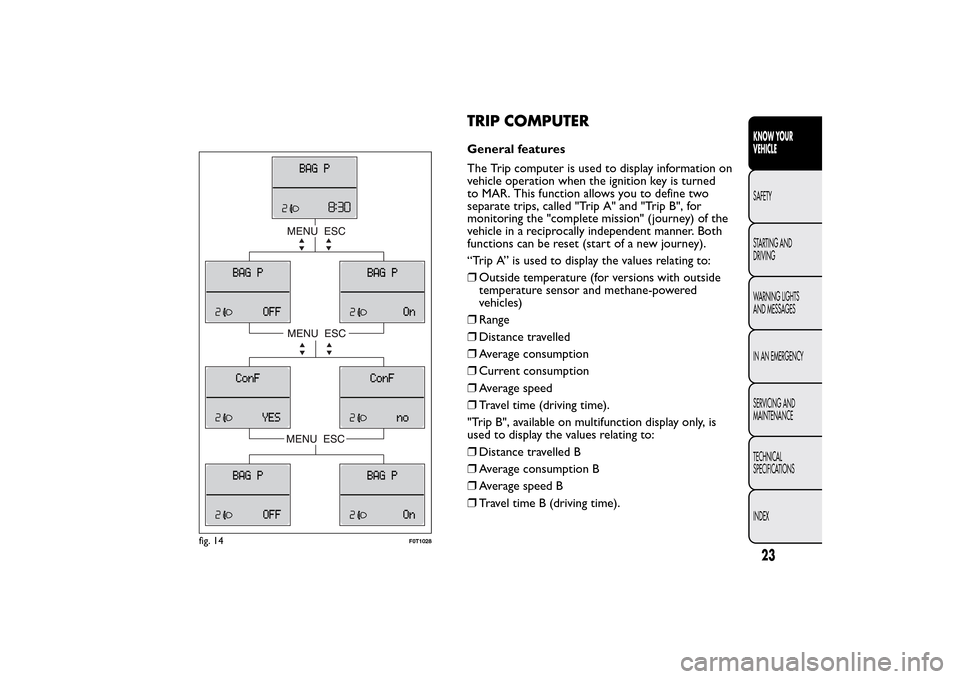
TRIP COMPUTERGeneral features
The Trip computer is used to display information on
vehicle operation when the ignition key is turned
to MAR. This function allows you to define two
separate trips, called "Trip A" and "Trip B", for
monitoring the "complete mission" (journey) of the
vehicle in a reciprocally independent manner. Both
functions can be reset (start of a new journey).
“Trip A” is used to display the values relating to:
❒Outside temperature (for versions with outside
temperature sensor and methane-powered
vehicles)
❒Range
❒Distance travelled
❒Average consumption
❒Current consumption
❒Average speed
❒Travel time (driving time).
"Trip B", available on multifunction display only, is
used to display the values relating to:
❒Distance travelled B
❒Average consumption B
❒Average speed B
❒Travel time B (driving time).
fig. 14
F0T1028
23KNOW YOUR
VEHICLESAFETY
STARTING AND
DRIVING
WARNING LIGHTS
AND MESSAGES
IN AN EMERGENCY
SERVICING AND
MAINTENANCE
TECHNICAL
SPECIFICATIONS
INDEX
Page 81 of 231
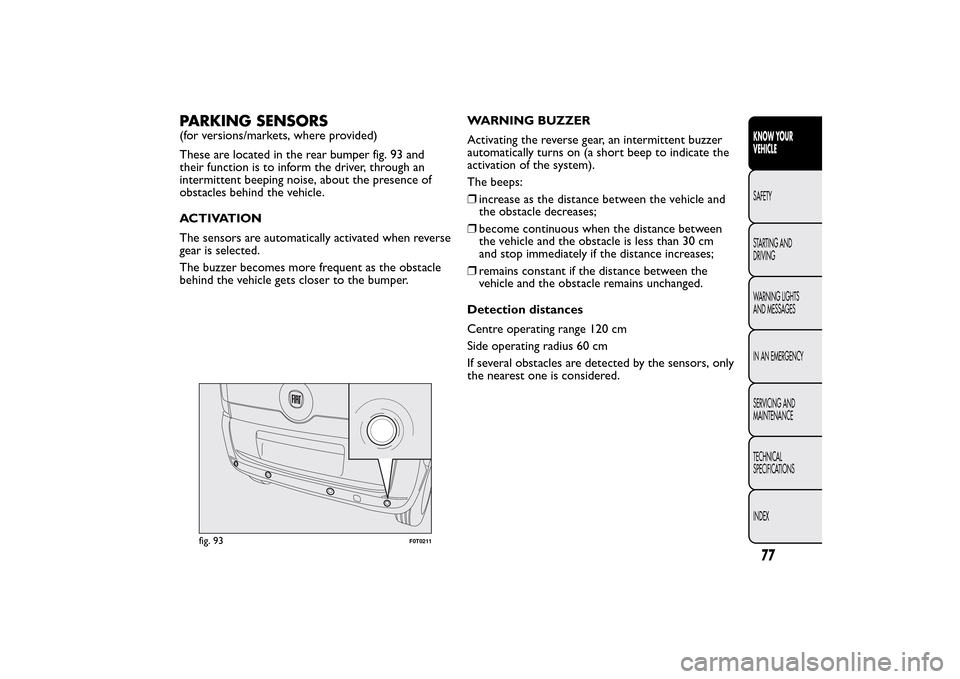
PARKING SENSORS(for versions/markets, where provided)
These are located in the rear bumper fig. 93 and
their function is to inform the driver, through an
intermittent beeping noise, about the presence of
obstacles behind the vehicle.
ACTIVATION
The sensors are automatically activated when reverse
gear is selected.
The buzzer becomes more frequent as the obstacle
behind the vehicle gets closer to the bumper.WARNING BUZZER
Activating the reverse gear, an intermittent buzzer
automatically turns on (a short beep to indicate the
activation of the system).
The beeps:
❒increase as the distance between the vehicle and
the obstacle decreases;
❒become continuous when the distance between
the vehicle and the obstacle is less than 30 cm
and stop immediately if the distance increases;
❒remains constant if the distance between the
vehicle and the obstacle remains unchanged.
Detection distances
Centre operating range 120 cm
Side operating radius 60 cm
If several obstacles are detected by the sensors, only
the nearest one is considered.
fig. 93
F0T0211
77KNOW YOUR
VEHICLESAFETY
STARTING AND
DRIVING
WARNING LIGHTS
AND MESSAGES
IN AN EMERGENCY
SERVICING AND
MAINTENANCE
TECHNICAL
SPECIFICATIONS
INDEX
Page 82 of 231
FAILURE INDICATIONS
Parking sensor failures are indicated, when engaging
reverse gear, by a three-second beep.
The sensor must be free of mud, dirt , snow
or ice in order for the system to work. Be
careful not to scratch or damage the
sensors while cleaning them. Avoid using dr y,
rough or hard cloths.The sensors should be
washed using clean water with the addition of car
shampoo if necessary.When using special
washing equipment such as high pressure jets or
steam cleaning, clean the sensors very quickly
keeping the jet more than 10 cm away.
OPERATION WITH TRAILER
The operation of the sensors is automatically
deactivated when the plug for the electric cable for
the trailer is inserted in the vehicle tow hook socket.
The sensors are automatically enabled again when
the trailer cable plug is removed.GENERAL WARNINGS
❒During parking manoeuvres, pay the utmost
attention to any obstacles that could be located
above or below the sensors.
❒Sometimes, objects located very near the rear of
the vehicle are not detected and could therefore
damage the vehicle or be damaged themselves.
❒The signals sent out by the sensors can be altered
by dirt, snow or ice deposited on the sensors or
by ultrasound systems (e.g. truck pneumatic brakes
or pneumatic drills) near the vehicle.
❒The parking sensors work properly with the swing
doors closed. If they are open, they can cause the
system to send false signals: always close the
rear doors.
WARNING
The ultimate responsibility when
parking and carrying out other
dangerous manoeuvres still rests with the
driver.When parking, make sure that no-one is
standing in the area, especially children or
animals. Parking sensors are designed to assist
drivers; however, you must always concentrate
fully during potentially dangerous manoeuvres,
even if carried out at low speeds.
78KNOW YOUR
VEHICLE
SAFETY
STARTING AND
DRIVING
WARNING LIGHTS
AND MESSAGES
IN AN EMERGENCY
SERVICING AND
MAINTENANCE
TECHNICAL
SPECIFICATIONS
INDEX
Page 131 of 231
GENERIC FAILURE INDICATION
(amber)
The warning light turns on in the following
circumstances:
Engine oil pressure sensor failure
The warning light turns on when an engine oil
pressure sensor failure is detected.
Go to a Fiat Dealership to have the fault fixed as
soon as possible.
Exterior lights fault
(for versions/markets, where provided)
See exterior lights warning light section.
Fuel cut-off inertia switch tripped
The warning light switches on when the fuel cut-off
inertia switch is tripped.
The display will show a dedicated message.
Parking sensor failure
(for versions/markets, where provided)
See parking sensor warning light section.
BRAKE PAD WEAR (amber)
The warning light goes on if the front brake pads are
worn. In this case replace them as soon as possible.
A specific message is displayed on certain versions.PARKING SENSOR FAULT (yellow)
(for versions/markets, where provided)
The warning light turns on when a parking sensor
fault is detected.
On certain versions warning light
comes on
instead.
In this case, contact a Fiat Dealership.
A specific message is displayed on certain versions.
SIDE/TAIL LIGHTS (green) -
FOLLOW ME HOME (green)
Side lights/tail lights
The warning light comes on when the side/taillights
are turned on.
127KNOW YOUR
VEHICLE
SAFETY
STARTING AND
DRIVINGWARNING LIGHTS
AND MESSAGESIN AN EMERGENCY
SERVICING AND
MAINTENANCE
TECHNICAL
SPECIFICATIONS
INDEX
Page 164 of 231
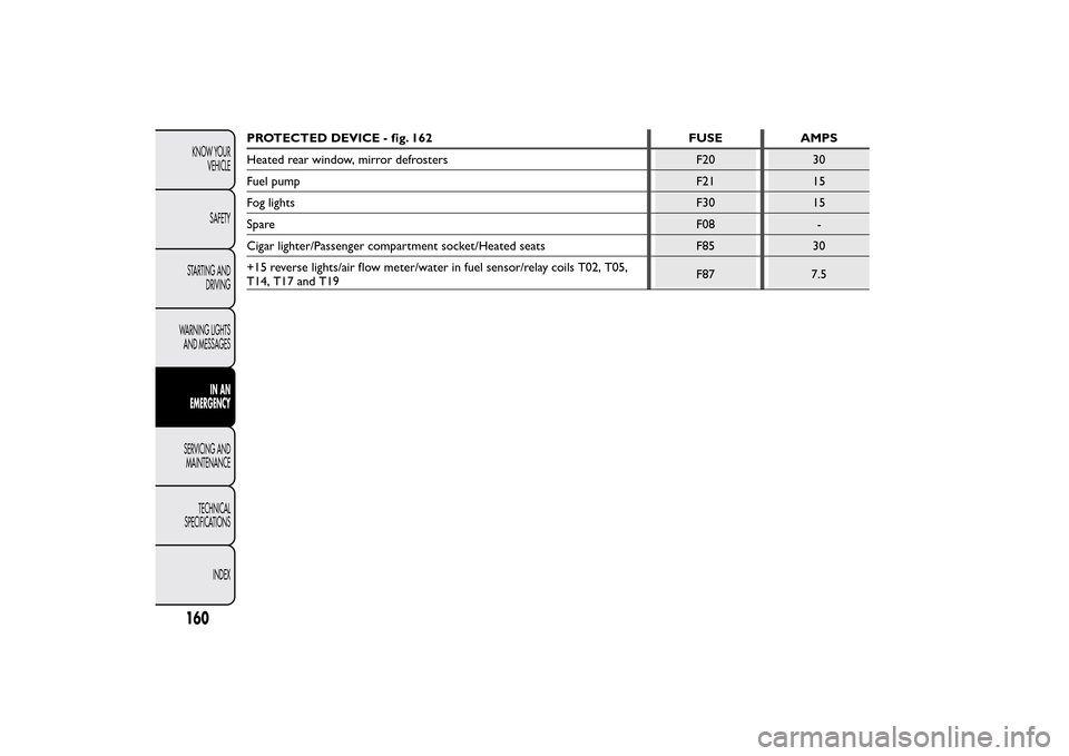
PROTECTED DEVICE - fig. 162 FUSE AMPS
Heated rear window, mirror defrosters F20 30
Fuel pump F21 15
Fog lights F30 15
SpareF08 -
Cigar lighter/Passenger compartment socket/Heated seats F85 30
+15 reverse lights/air flow meter/water in fuel sensor/relay coils T02, T05,
T14, T17 and T19F87 7.5
160KNOW YOUR
VEHICLE
SAFETY
STARTING AND
DRIVING
WARNING LIGHTS
AND MESSAGES
IN AN
EMERGENCY
SERVICING AND
MAINTENANCE
TECHNICAL
SPECIFICATIONS
INDEX
Page 166 of 231
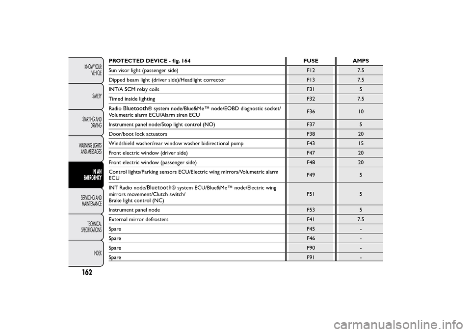
PROTECTED DEVICE - fig. 164 FUSE AMPS
Sun visor light (passenger side) F12 7.5
Dipped beam light (driver side)/Headlight corrector F13 7.5
INT/A SCM relay coils F31 5
Timed inside lighting F32 7.5
Radio
Bluetooth
®system node/Blue&Me™ node/EOBD diagnostic socket/
Volumetric alarm ECU/Alarm siren ECUF36 10
Instrument panel node/Stop light control (NO) F37 5
Door/boot lock actuators F38 20
Windshield washer/rear window washer bidirectional pump F43 15
Front electric window (driver side) F47 20
Front electric window (passenger side) F48 20
Control lights/Parking sensors ECU/Electric wing mirrors/Volumetric alarm
ECUF49 5
INT Radio node/Bluetooth
®system ECU/Blue&Me™ node/Electric wing
mirrors movement/Clutch switch/
Brake light control (NC)F51 5
Instrument panel node F53 5
External mirror defrosters F41 7.5
SpareF45 -
SpareF46 -
SpareF90 -
SpareF91 -
162KNOW YOUR
VEHICLE
SAFETY
STARTING AND
DRIVING
WARNING LIGHTS
AND MESSAGES
IN AN
EMERGENCY
SERVICING AND
MAINTENANCE
TECHNICAL
SPECIFICATIONS
INDEX
Page 227 of 231
Jump starting............................... 129Keys
– Key without remote
control ..................................... 6
– Key with remote control..... 7
– Ordering additional
remote controls .................... 8Left direction indicator
warning light ............................. 128
Lifting the vehicle....................... 165
Light beam direction .................. 68
Low battery charge warning
light ............................................. 121
Low engine oil level ................... 122
Low engine oil pressure
warning light.............................. 122M
ain beam headlights ............... 41
Maintenance and care -
regular checks........................... 171
Maintenance and care -
Scheduled Servicing ................. 168
Maintenance and care -
scheduled servicing plan......... 169
Manual climate control
system ......................................... 38Manual deactivation of
passenger front airbag and
side bag ...................................... 103
MSR system.................................. 73
Multifunction display
– Control buttons .................... 15
– Setup menu............................. 16
– Standard screen ..................... 14
N
umber plate lights (bulb
replacement)............................. 151
Number plate lights................... 151
O
ddment tray ............................. 49
Ordering additional remote
controls ....................................... 8
Parking......................................... 111
Parking lights ................................ 41
Parking sensor fault warning
light ............................................. 127
Parking sensors ........................... 77
Parking sensors (warning
light) ............................................ 127
Particulate filter (DPF) .............. 84
Partition ........................................ 29
Passenger air bag/side bag
off warning light ....................... 119
Passenger air bag/side bag
(warning light)........................... 119Passenger compartment
fuse box ..................................... 161
Passenger compartment
fuse box table ........................... 161
Performance................................ 203
Pollen filter .................................. 180
Power steering fluid .................. 179
Pressure check and
correction.................................. 141
Pretensioners............................... 87
Prolonged vehicle inactivity ..... 117
Protecting the environment ..... 84
Radio ............................................. 79
Radio transmitters and
mobile phones ........................... 80
Rear ceiling light ......................... 153
Rear fog lights (changing a
bulb) ............................................ 149
Rear fog lights .............................. 48
– Warning light ......................... 128
Rear fog lights warning light .... 128
Rear light clusters (changing
a bulb)......................................... 149
Rear light clusters ...................... 149
Rear side windows ..................... 51
Rear-view mirrors
– Interior rear-view mirror..... 32
223KNOW YOUR
VEHICLE
SAFETY
STARTING AND
DRIVING
WARNING LIGHTS
AND MESSAGES
IN AN EMERGENCY
SERVICING AND
MAINTENANCE
TECHNICAL
SPECIFICATIONSINDEX