FIAT QUBO 2016 1.G Owners Manual
Manufacturer: FIAT, Model Year: 2016, Model line: QUBO, Model: FIAT QUBO 2016 1.GPages: 231, PDF Size: 5.02 MB
Page 131 of 231
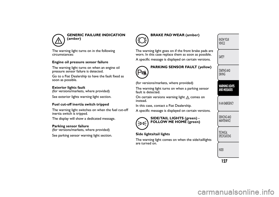
GENERIC FAILURE INDICATION
(amber)
The warning light turns on in the following
circumstances:
Engine oil pressure sensor failure
The warning light turns on when an engine oil
pressure sensor failure is detected.
Go to a Fiat Dealership to have the fault fixed as
soon as possible.
Exterior lights fault
(for versions/markets, where provided)
See exterior lights warning light section.
Fuel cut-off inertia switch tripped
The warning light switches on when the fuel cut-off
inertia switch is tripped.
The display will show a dedicated message.
Parking sensor failure
(for versions/markets, where provided)
See parking sensor warning light section.
BRAKE PAD WEAR (amber)
The warning light goes on if the front brake pads are
worn. In this case replace them as soon as possible.
A specific message is displayed on certain versions.PARKING SENSOR FAULT (yellow)
(for versions/markets, where provided)
The warning light turns on when a parking sensor
fault is detected.
On certain versions warning light
comes on
instead.
In this case, contact a Fiat Dealership.
A specific message is displayed on certain versions.
SIDE/TAIL LIGHTS (green) -
FOLLOW ME HOME (green)
Side lights/tail lights
The warning light comes on when the side/taillights
are turned on.
127KNOW YOUR
VEHICLE
SAFETY
STARTING AND
DRIVINGWARNING LIGHTS
AND MESSAGESIN AN EMERGENCY
SERVICING AND
MAINTENANCE
TECHNICAL
SPECIFICATIONS
INDEX
Page 132 of 231
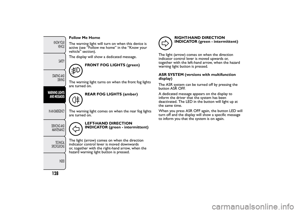
Follow Me Home
The warning light will turn on when this device is
active (see “Follow me home” in the “Know your
vehicle” section).
The display will show a dedicated message.
FRONT FOG LIGHTS (green)
The warning light turns on when the front fog lights
are turned on.REAR FOG LIGHTS (amber)
The warning light comes on when the rear fog lights
are turned on.LEFT-HAND DIRECTION
INDICATOR (green - intermittent)
The light (arrow) comes on when the direction
indicator control lever is moved downwards
or, together with the right-hand arrow, when the
hazard warning light button is pressed.
RIGHT-HAND DIRECTION
INDICATOR (green - intermittent)
The light (arrow) comes on when the direction
indicator control lever is moved upwards or,
together with the left-hand arrow, when the hazard
warning light button is pressed.
ASR SYSTEM (versions with multifunction
display)
The ASR system can be turned off by pressing the
button ASR OFF.
A dedicated message appears on the display to
inform the driver that the system has been
deactivated. The LED in the button will light up at
the same time.
When you press ASR OFF again, the button LED will
turn off and the display will show a specific message
to inform you that the system is on again.
128KNOW YOUR
VEHICLE
SAFETY
STARTING AND
DRIVING
WARNING LIGHTS
AND MESSAGESIN AN EMERGENCY
SERVICING AND
MAINTENANCE
TECHNICAL
SPECIFICATIONS
INDEX
Page 133 of 231
IN AN EMERGENCY
In an emergency, we recommend that you call the freephone number found in the Warranty
Booklet.You can also go to the www.fiat.com website to find your nearest Fiat Dealership.STARTING THE ENGINEGo to a Fiat Dealership immediately if warning light
comes on steady on the instrument panel.
JUMP STARTING
If the battery is flat, the engine may be started using
an auxiliary battery with capacity either the same
or a little higher than the flat one.
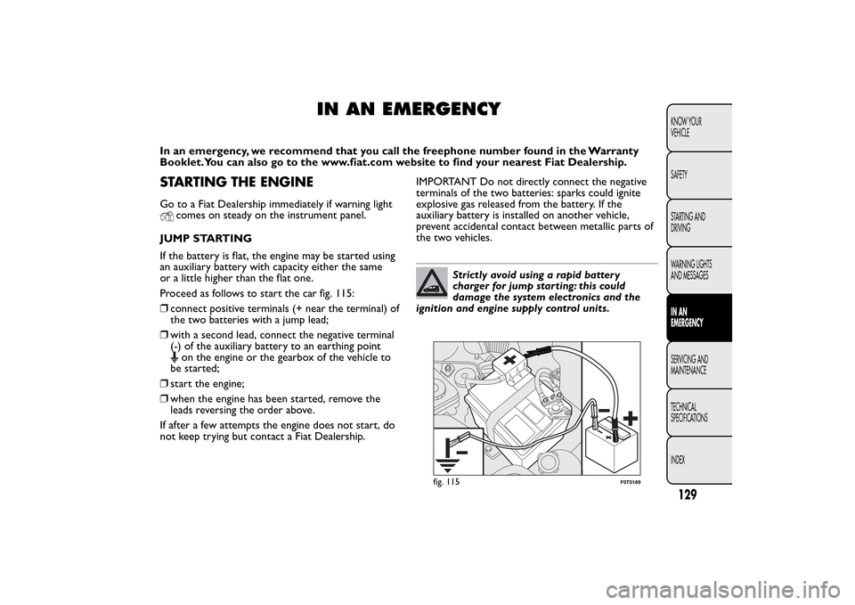
Proceed as follows to start the car fig. 115:
❒connect positive terminals (+ near the terminal) of
the two batteries with a jump lead;
❒with a second lead, connect the negative terminal
(-) of the auxiliary battery to an earthing pointon the engine or the gearbox of the vehicle to
be started;
❒start the engine;
❒when the engine has been started, remove the
leads reversing the order above.
If after a few attempts the engine does not start, do
not keep trying but contact a Fiat Dealership.IMPORTANT Do not directly connect the negative
terminals of the two batteries: sparks could ignite
explosive gas released from the battery. If the
auxiliary battery is installed on another vehicle,
prevent accidental contact between metallic parts of
the two vehicles.
Strictly avoid using a rapid battery
charger for jump starting: this could
damage the system electronics and the
ignition and engine supply control units.
fig. 115
F0T0189
129KNOW YOUR
VEHICLE
SAFETY
STARTING AND
DRIVING
WARNING LIGHTS
AND MESSAGESIN AN
EMERGENCYSERVICING AND
MAINTENANCE
TECHNICAL
SPECIFICATIONS
INDEX
Page 134 of 231
WARNING
This procedure must be performed by
experts because incorrect actions may
cause considerable electrical discharge.
Furthermore, batter y fluid is poisonous and
corrosive: avoid contact with skin and eyes.
Keep naked flames and lit cigarettes away from
the battery. Do not create sparks.
BUMP STARTING
Never bump start the engine by pushing, towing or
driving downhill. This could cause fuel to flow into
the catalytic converter and damage it beyond repair.
IMPORTANT Remember that the brake booster
and the power steering system are not active until
the engine is started, so you will need to apply much
more force to the brake pedal or steering wheel.
CHANGING A TYREThe vehicle is originally equipped with the Fix&Go
automatic quick tyre repair kit (see instructions
in the next chapter). As an alternative, the vehicle
may have a normal-sized spare wheel.
Changing the wheel and correct use of the jack and
spare wheel require some precautions, which are
listed below.
WARNING
The spare wheel (for versions/markets,
where provided) is specific for your
vehicle.Therefore, it must not be used on other
models. Do not use spare wheels of other
models on your vehicle.The spare wheel must
be used only in an emergency. Use of the spare
wheel must kept to the minimum necessar y.
130KNOW YOUR
VEHICLE
SAFETY
STARTING AND
DRIVING
WARNING LIGHTS
AND MESSAGES
IN AN
EMERGENCY
SERVICING AND
MAINTENANCE
TECHNICAL
SPECIFICATIONS
INDEX
Page 135 of 231
WARNING
Use your hazard lights, warning triangle,
etc . to show that your vehicle is
stationary according to the regulations in force.
Passengers should get out of the vehicle,
particularly if it is heavily loaded, and wait for
the wheel to be changed away from the traffic .
If you are on a slope or uneven surface, place
wedges or other suitable objects under the
wheels to secure the vehicle. Have the standard
wheel repaired and refitted as soon as possible.
Do not apply grease to the bolt threads before
fitting: they could unscrew themselves.
WARNING
Use the jack only to replace wheels on
the vehicle with which it is supplied
or on other vehicles of the same model. Never
use the jack for other purposes, such as lifting
other models. Never use the jack to carr y out
repairs under the vehicle. Incorrect positioning
of the jack may cause the raised vehicle to
fall. Do not use the jack for loads higher than
the one shown on its label.
WARNING
Incorrect hub cap assembly may cause it
to come off when the car is moving.
Never tamper with the inflation valve. Never
introduce tools of any kind between rim and
tyre. Check tyre and spare wheel pressures
regularly, complying with the values given in the
"Technical specifications" chapter.
Important notes:
❒the jack weighs 1.76 kg;
❒the jack requires no adjustment;
❒the jack cannot be repaired; if it breaks, it must be
replaced with a new one of the same type;
❒no tool other than the cranking handle may be
fitted on the jack.
To change a wheel proceed as follows:
❒stop the vehicle in a position where it is not a
danger for other traffic and where you can replace
the wheel safely. The ground should be flat and
solid;
❒stop the engine off and pull up the handbrake;
❒engage first gear or reverse;
❒wear the reflective safety jacket (compulsory by
law) before getting out of the vehicle;
131KNOW YOUR
VEHICLE
SAFETY
STARTING AND
DRIVING
WARNING LIGHTS
AND MESSAGESIN AN
EMERGENCYSERVICING AND
MAINTENANCE
TECHNICAL
SPECIFICATIONS
INDEX
Page 136 of 231
❒indicate that the vehicle is parked up by using the
devices required by law in the country in which
you are travelling (e.g. warning triangle, hazard
lights etc.);
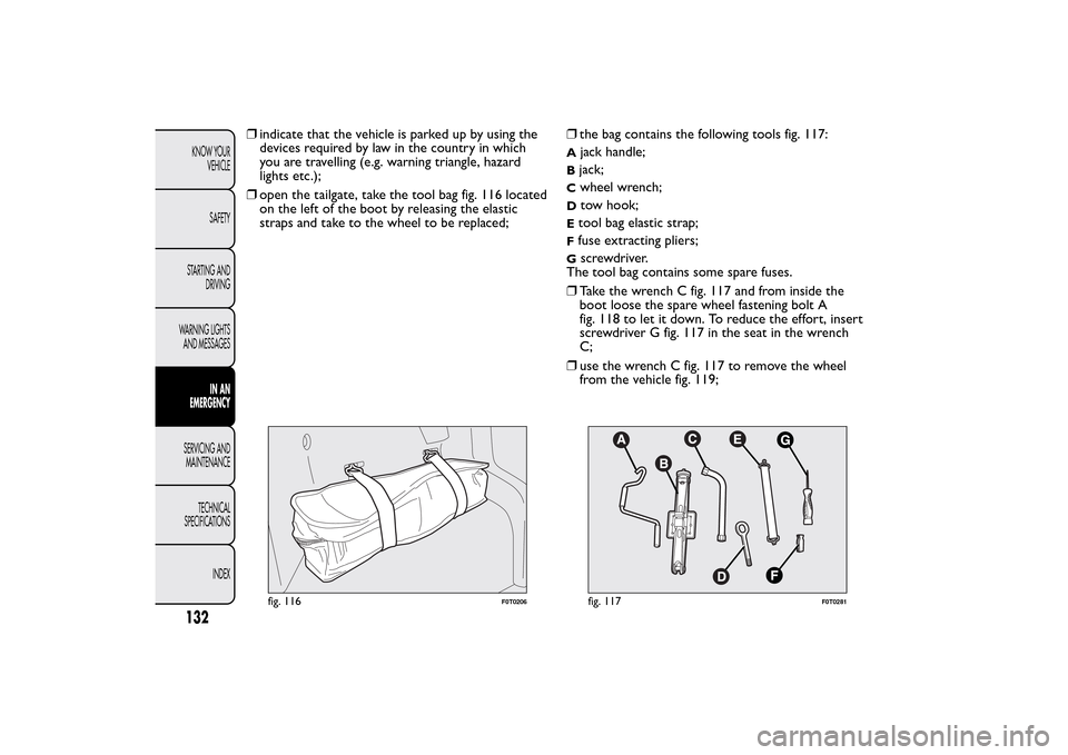
❒open the tailgate, take the tool bag fig. 116 located
on the left of the boot by releasing the elastic
straps and take to the wheel to be replaced;❒the bag contains the following tools fig. 117:
A
jack handle;
Bjack;C
wheel wrench;
D
tow hook;
Etool bag elastic strap;Ffuse extracting pliers;G
screwdriver.
The tool bag contains some spare fuses.
❒Take the wrench C fig. 117 and from inside the
boot loose the spare wheel fastening bolt A
fig. 118 to let it down. To reduce the effort, insert
screwdriver G fig. 117 in the seat in the wrench
C;
❒use the wrench C fig. 117 to remove the wheel
from the vehicle fig. 119;
fig. 116
F0T0206
fig. 117
F0T0281
132KNOW YOUR
VEHICLE
SAFETY
STARTING AND
DRIVING
WARNING LIGHTS
AND MESSAGES
IN AN
EMERGENCY
SERVICING AND
MAINTENANCE
TECHNICAL
SPECIFICATIONS
INDEX
Page 137 of 231
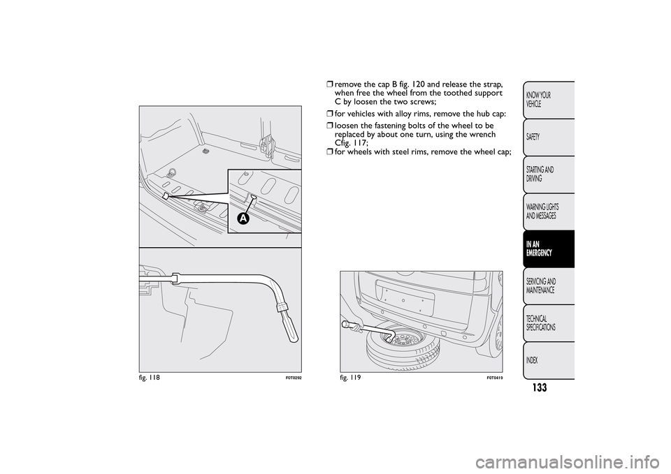
❒remove the cap B fig. 120 and release the strap,
when free the wheel from the toothed support
C by loosen the two screws;
❒for vehicles with alloy rims, remove the hub cap:
❒loosen the fastening bolts of the wheel to be
replaced by about one turn, using the wrench
Cfig. 117;
❒for wheels with steel rims, remove the wheel cap;
A
fig. 118
F0T0292
fig. 119
F0T0419
133KNOW YOUR
VEHICLE
SAFETY
STARTING AND
DRIVING
WARNING LIGHTS
AND MESSAGESIN AN
EMERGENCYSERVICING AND
MAINTENANCE
TECHNICAL
SPECIFICATIONS
INDEX
Page 138 of 231
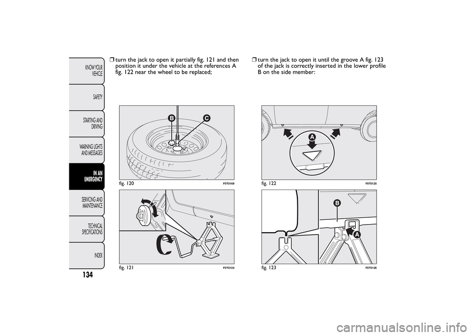
❒turn the jack to open it partially fig. 121 and then
position it under the vehicle at the references A
fig. 122 near the wheel to be replaced;❒turn the jack to open it until the groove A fig. 123
of the jack is correctly inserted in the lower profile
B on the side member:
fig. 120
F0T0169
fig. 121
F0T0124
fig. 122
F0T0125
fig. 123
F0T0126
134KNOW YOUR
VEHICLE
SAFETY
STARTING AND
DRIVING
WARNING LIGHTS
AND MESSAGES
IN AN
EMERGENCY
SERVICING AND
MAINTENANCE
TECHNICAL
SPECIFICATIONS
INDEX
Page 139 of 231
❒warn anybody nearby that the vehicle is about to
be lifted. They must stay clear and not touch the
vehicle until it is back on the ground.
❒operate the jack and lift the vehicle until the wheel
is several centimetres off the ground. When
turning the crank, ensure that it rotates freely in
order to avoid grazing your hands against the
ground. The moving components of the jack
(screws and joints) can also cause injuries, so do
not touch them. If you become soiled with the
lubricating grease, wash it off thoroughly;❒fully loosen the fastening bolts and remove the
wheel;
❒make sure the contact surfaces between spare
wheel and hub are clean so that the fastening bolts
will not come loose;
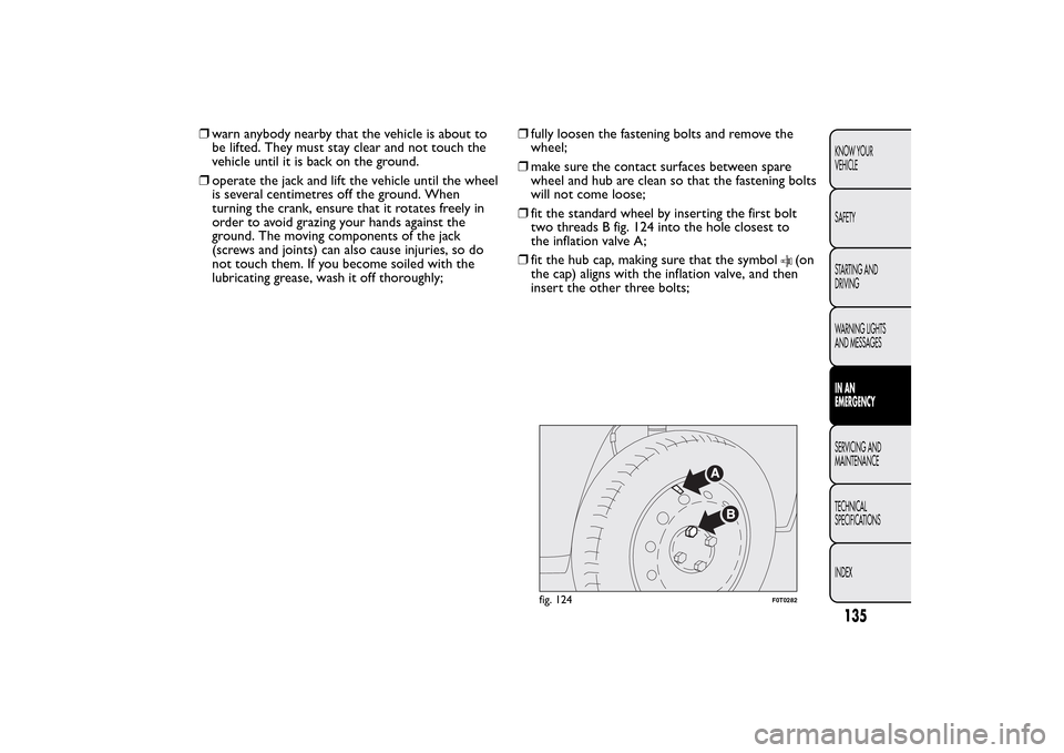
❒fit the standard wheel by inserting the first bolt
two threads B fig. 124 into the hole closest to
the inflation valve A;
❒fit the hub cap, making sure that the symbol
(on
the cap) aligns with the inflation valve, and then
insert the other three bolts;
fig. 124
F0T0282
135KNOW YOUR
VEHICLE
SAFETY
STARTING AND
DRIVING
WARNING LIGHTS
AND MESSAGESIN AN
EMERGENCYSERVICING AND
MAINTENANCE
TECHNICAL
SPECIFICATIONS
INDEX
Page 140 of 231
❒tighten the bolts using the wrench provided;
❒for vehicles with alloy rim, fit the hub cap;
❒turn the jack handle to lower the vehicle, and
remove the jack;
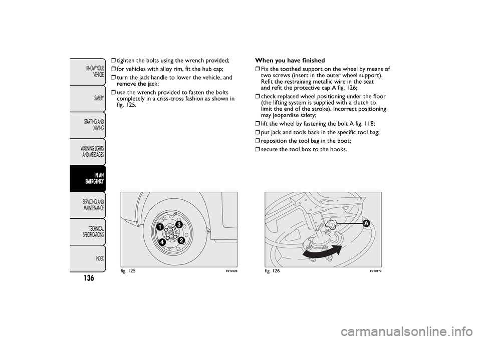
❒use the wrench provided to fasten the bolts
completely in a criss-cross fashion as shown in
fig. 125.When you have finished
❒Fix the toothed support on the wheel by means of
two screws (insert in the outer wheel support).
Refit the restraining metallic wire in the seat
and refit the protective cap A fig. 126;
❒check replaced wheel positioning under the floor
(the lifting system is supplied with a clutch to
limit the end of the stroke). Incorrect positioning
may jeopardise safety;
❒lift the wheel by fastening the bolt A fig. 118;
❒put jack and tools back in the specific tool bag;
❒reposition the tool bag in the boot;
❒secure the tool box to the hooks.
fig. 125
F0T0128
fig. 126
F0T0170
136KNOW YOUR
VEHICLE
SAFETY
STARTING AND
DRIVING
WARNING LIGHTS
AND MESSAGES
IN AN
EMERGENCY
SERVICING AND
MAINTENANCE
TECHNICAL
SPECIFICATIONS
INDEX