mirror controls FIAT SCUDO 2008 2.G Owners Manual
[x] Cancel search | Manufacturer: FIAT, Model Year: 2008, Model line: SCUDO, Model: FIAT SCUDO 2008 2.GPages: 210, PDF Size: 3.32 MB
Page 5 of 210
4
SAFETY
DEVICES
CORRECT USE
OF THE
VEHICLE
WARNING
LIGHTS AND
MESSAGES
IN AN
EMERGENCY
VEHICLE
MAINTENANCE
TECHNICAL
SPECIFICATIONS
INDEX
DASHBOARD
AND CONTROLSDASHBOARD ...................................................................... 5
SYMBOLS ............................................................................... 6
THE FIAT CODE SYSTEM ................................................. 6
THE KEYS .............................................................................. 7
ALARM ................................................................................... 10
IGNITION DEVICE ............................................................. 12
INSTRUMENT PANEL ........................................................ 13
INSTRUMENTS .................................................................... 14
DISPLAY.................................................................................. 15
MAINTENANCE INDICATOR ........................................ 16
TRIP COMPUTER................................................................. 17
FRONT SEATS ..................................................................... 17
REAR SEATS .......................................................................... 20
SEAT ARRANGEMENTS .................................................... 22
HEAD RESTRAINTS ........................................................... 23
STEERING WHEEL .............................................................. 24
REARVIEW MIRRORS ........................................................ 25
HEATING AND VENTILATION ..................................... 27
MANUAL CLIMATE CONTROL SYSTEM .................... 31
AUTOMATIC TWO-ZONE CLIMATE
CONTROL SYSTEM ........................................................... 37
AUTOMATIC THREE-ZONE CLIMATE
CONTROL SYSTEM ........................................................... 45
EXTERNAL LIGHTS ............................................................ 47WINDOW WASHING ...................................................... 50
CRUISE CONTROL SPEED REGULATOR.................... 54
“LIMIT” SPEED RESTRICTOR .......................................... 57
CEILING LIGHTS ................................................................. 60
CONTROLS .......................................................................... 61
FUEL CUT-OFF SWITCH .................................................. 64
INTERIOR EQUIPMENT..................................................... 65
DOORS .................................................................................. 69
SLIDING LUGGAGE COVER............................................ 73
POWER WINDOWS/WINDOW WINDERS .............. 74
BONNET ............................................................................... 76
ROOF RACK/SKI RACK .................................................... 77
PNEUMATIC SUSPENSIONS............................................. 78
LOAD RECOMMENDATIONS......................................... 79
HEADLIGHTS ....................................................................... 81
ABS SYSTEM ......................................................................... 82
ESP SYSTEM .......................................................................... 84
EOBD SYSTEM ..................................................................... 87
PARKING SENSORS ........................................................... 88
SOUND SYSTEM ................................................................. 89
ACCESSORIES PURCHASED BY THE OWNER ......... 90
AT THE FILLING STATION ............................................. 91
PROTECTING THE ENVIRONMENT ........................... 92
D D
A A
S S
H H
B B
O O
A A
R R
D D
A A
N N
D D
C C
O O
N N
T T
R R
O O
L L
S S
Page 16 of 210
15
SAFETY
DEVICES
CORRECT USE
OF THE
VEHICLE
WARNING
LIGHTS AND
MESSAGES
IN AN
EMERGENCY
VEHICLE
MAINTENANCE
TECHNICAL
SPECIFICATIONS
INDEX
DASHBOARD
AND CONTROLS
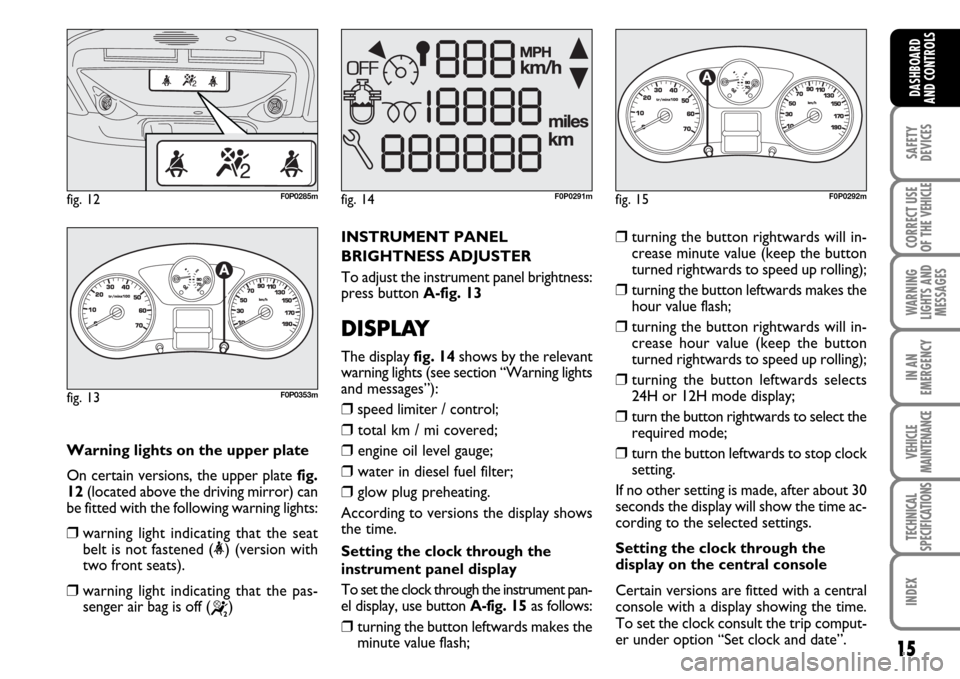
Warning lights on the upper plate
On certain versions, the upper plate fig.
12(located above the driving mirror) can
be fitted with the following warning lights:
❒warning light indicating that the seat
belt is not fastened (<) (version with
two front seats).
❒warning light indicating that the pas-
senger air bag is off (
“)
fig. 12F0P0285m
INSTRUMENT PANEL
BRIGHTNESS ADJUSTER
To adjust the instrument panel brightness:
press button A-fig. 13
DISPLAY
The display fig. 14shows by the relevant
warning lights (see section “Warning lights
and messages”):
❒speed limiter / control;
❒total km / mi covered;
❒engine oil level gauge;
❒water in diesel fuel filter;
❒glow plug preheating.
According to versions the display shows
the time.
Setting the clock through the
instrument panel display
To set the clock through the instrument pan-
el display, use button A-fig. 15as follows:
❒turning the button leftwards makes the
minute value flash;
❒turning the button rightwards will in-
crease minute value (keep the button
turned rightwards to speed up rolling);
❒turning the button leftwards makes the
hour value flash;
❒turning the button rightwards will in-
crease hour value (keep the button
turned rightwards to speed up rolling);
❒turning the button leftwards selects
24H or 12H mode display;
❒turn the button rightwards to select the
required mode;
❒turn the button leftwards to stop clock
setting.
If no other setting is made, after about 30
seconds the display will show the time ac-
cording to the selected settings.
Setting the clock through the
display on the central console
Certain versions are fitted with a central
console with a display showing the time.
To set the clock consult the trip comput-
er under option “Set clock and date”.
fig. 14F0P0291mfig. 15
1/2
F0P0292m
fig. 13
1/2
F0P0353m
Page 26 of 210
25
SAFETY
DEVICES
CORRECT USE
OF THE
VEHICLE
WARNING
LIGHTS AND
MESSAGES
IN AN
EMERGENCY
VEHICLE
MAINTENANCE
TECHNICAL
SPECIFICATIONS
INDEX
DASHBOARD
AND CONTROLS
REARVIEW MIRRORS
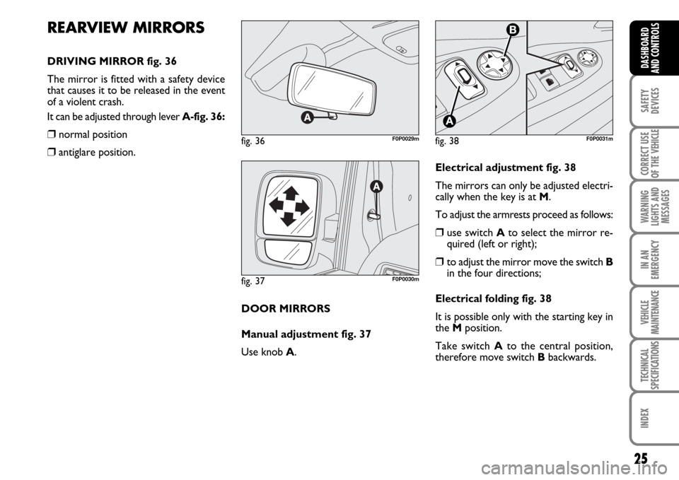
DRIVING MIRROR fig. 36
The mirror is fitted with a safety device
that causes it to be released in the event
of a violent crash.
It can be adjusted through lever A-fig. 36:
❒normal position
❒antiglare position.
fig. 36F0P0029m
fig. 37F0P0030m
DOOR MIRRORS
Manual adjustment fig. 37
Use knob A.
fig. 38F0P0031m
Electrical adjustment fig. 38
The mirrors can only be adjusted electri-
cally when the key is at M.
To adjust the armrests proceed as follows:
❒use switch Ato select the mirror re-
quired (left or right);
❒to adjust the mirror move the switch B
in the four directions;
Electrical folding fig. 38
It is possible only with the starting key in
the Mposition.
Take switch Ato the central position,
therefore move switch Bbackwards.
Page 27 of 210
26
SAFETY
DEVICES
CORRECT USE
OF THE
VEHICLE
WARNING
LIGHTS AND
MESSAGES
IN AN
EMERGENCY
VEHICLE
MAINTENANCE
TECHNICAL
SPECIFICATIONS
INDEX
DASHBOARD
AND
CONTROLS
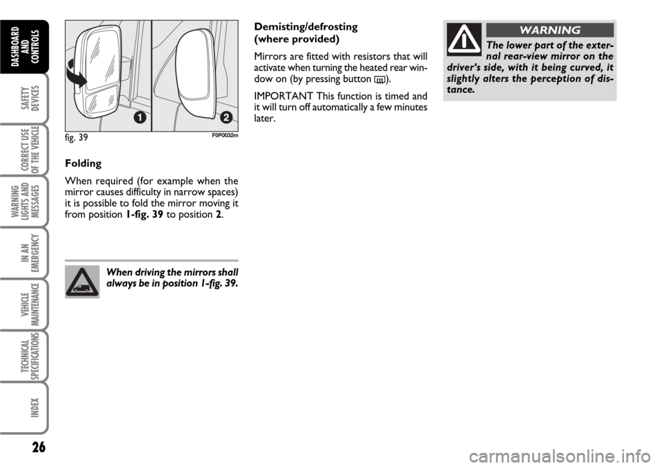
Folding
When required (for example when the
mirror causes difficulty in narrow spaces)
it is possible to fold the mirror moving it
from position 1-fig. 39to position 2.
When driving the mirrors shall
always be in position 1-fig. 39.
The lower part of the exter-
nal rear-view mirror on the
driver’s side, with it being curved, it
slightly alters the perception of dis-
tance.
WARNINGDemisting/defrosting
(where provided)
Mirrors are fitted with resistors that will
activate when turning the heated rear win-
dow on (by pressing button
().
IMPORTANT This function is timed and
it will turn off automatically a few minutes
later.
fig. 39F0P0032m
Page 31 of 210
30
SAFETY
DEVICES
CORRECT USE
OF THE
VEHICLE
WARNING
LIGHTS AND
MESSAGES
IN AN
EMERGENCY
VEHICLE
MAINTENANCE
TECHNICAL
SPECIFICATIONS
INDEX
DASHBOARD
AND
CONTROLS
FRONT WINDOW FAST
DEMISTING/
DEFROSTING (WINDSCREEN
AND SIDE WINDOWS)
Proceed as follows:
❒turn slider Cto red section;
❒turn air recirculation off (if on);
❒turn slider Ato -;
❒
turn slider Bto 4 -p(max. fan
speed).
After demisting/defrosting, operate the
controls to restore the required comfort.Window demisting
In the event of considerable outside mois-
ture and/or rain and/or considerable dif-
ferences in temperature inside and outside
the passenger compartment, perform the
following preventive demisting procedure:
❒turn slider Cto red section;
❒turn air recirculation off by pressing
button D(if off);
❒turn slider Ato -or to ∏if the win-
dows do not demist;
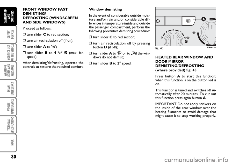
❒turn slider Bto 2ndspeed.HEATED REAR WINDOW AND
DOOR MIRROR
DEMISTING/DEFROSTING
(where provided) fig. 45
Press button Ato start this function;
when this function is on the button led is
on.
This function is timed and switches off au-
tomatically after 20 minutes. To cut out
this function press again button A.
IMPORTANT Do not apply stickers on
the inside of the rear window over the
heating filaments to avoid damage that
might cause it to stop working properly.
fig. 45F0P0037m
Page 36 of 210
35
SAFETY
DEVICES
CORRECT USE
OF THE
VEHICLE
WARNING
LIGHTS AND
MESSAGES
IN AN
EMERGENCY
VEHICLE
MAINTENANCE
TECHNICAL
SPECIFICATIONS
INDEX
DASHBOARD
AND CONTROLS
Window demisting
In the event of considerable outside mois-
ture and/or rain and/or considerable dif-
ferences in temperature inside and outside
the passenger compartment, perform the
following preventive demisting procedure:
❒turn slider Cto red section;
❒turn air recirculation off by pressing
button D(if on);
❒turn slider Ato -or to ®if the win-
dows do not demist;
❒turn slider Bto 2ndspeed.
IMPORTANT The climate control system
is very useful to prevent window misting
up in presence of high humidity since it de-
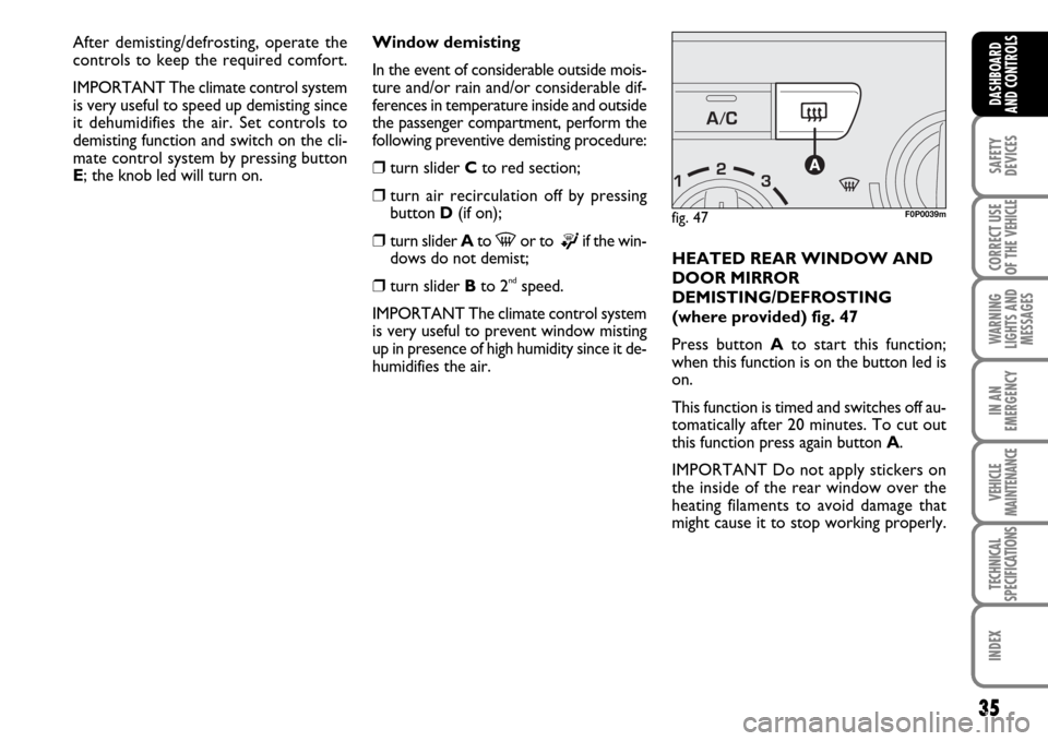
humidifies the air.HEATED REAR WINDOW AND
DOOR MIRROR
DEMISTING/DEFROSTING
(where provided) fig. 47
Press button Ato start this function;
when this function is on the button led is
on.
This function is timed and switches off au-
tomatically after 20 minutes. To cut out
this function press again button A.
IMPORTANT Do not apply stickers on
the inside of the rear window over the
heating filaments to avoid damage that
might cause it to stop working properly.
fig. 47F0P0039m
After demisting/defrosting, operate the
controls to keep the required comfort.
IMPORTANT The climate control system
is very useful to speed up demisting since
it dehumidifies the air. Set controls to
demisting function and switch on the cli-
mate control system by pressing button
E; the knob led will turn on.
Page 40 of 210

39
SAFETY
DEVICES
CORRECT USE
OF THE
VEHICLE
WARNING
LIGHTS AND
MESSAGES
IN AN
EMERGENCY
VEHICLE
MAINTENANCE
TECHNICAL
SPECIFICATIONS
INDEX
DASHBOARD
AND CONTROLS
During fully automatic operation, the on-
ly manual settings required are the fol-
lowing:
❒Ωair recirculation, to keep it always
on or off;
❒-to speed up demisting/defrosting
of windscreen, side windows, rear win-
dow and door mirrors;
❒(to demist/defrost heated rear win-
dow and door mirrors;
❒πto select air distribution during ven-
tilation.
During full automatic system operation,
you can change at any time set tempera-
tures, air distribution and fan speed by us-
ing the relevant buttons or knobs: the sys-
tem will automatically change its settings
to adjust to the new requirements.Air temperature adjusting knobs
M - I
Turning the knobs clockwise or counter-
clockwise, respectively increases or de-
creases the temperature of the air required
respectively in the front left zone (knob M)
and in the right zone (knob I) f the passen-
ger compartment. Since the system controls
two zones of the passenger compartment,
it is possible to personalise required tem-
peratures (driver and passenger) with a
maximum difference of 7 °C.
The temperatures set are shown on the dis-
play near the relevant knobs. Pressing but-
ton AUTOwill activate automatic opera-
tion in order to have two separate ventila-
tion temperatures between driver and pas-
senger’s side.
With automatic operation on, pressing again
button AUTOwill align the temperature
on the passenger’s side with that on the dri-
ver’s side.
Turn the knobs fully clockwise or counter-
clockwise to engage respectively HI(max-
imum heating) or LO(maximum cooling).
To deactivate these two functions, just
turn the temperature knob and set the re-
quired temperature.Front air distribution button D
Pressing this button it is possible to
choose manually one of the seven possi-
ble air distributions to the passenger com-
partment (right or left side):
æAir flow to the windscreen and front
side window vents to demist or de-
frost them.
øAir flow at central and side dash-
board vents to ventilate the chest and
the face during the hot season.
¿Air flow towards the front and rear
lower parts of the passenger com-
partment. Due to the natural ten-
dency of heat to spread upwards, this
type of distribution allows heating of
the passenger compartment in the
shortest time, also giving a prompt
feeling of warmth.
Page 44 of 210

43
SAFETY
DEVICES
CORRECT USE
OF THE
VEHICLE
WARNING
LIGHTS AND
MESSAGES
IN AN
EMERGENCY
VEHICLE
MAINTENANCE
TECHNICAL
SPECIFICATIONS
INDEX
DASHBOARD
AND CONTROLS
Fast window demisting/defrosting
button C
Press this button: the climate control sys-
tem will automatically switch on all the
functions required for fast windscreen and
front side window demisting/defrosting,
that is:
❒switches on climate control compressor
when climatic conditions are suitable;
❒air recirculation off;
❒maximum air temperature HIon both
areas;
❒activates proper fan speed according to
engine coolant temperature to limit the
flow into the passenger compartment of
air not warm enough to demist the win-
dows;
❒directs air flow to windscreen and front
side windows vents;
❒turns heated rear window on.
IMPORTANT Fast demisting/defrosting
function stays on for about 3 minutes,
since engine coolant temperature reach-
es the proper temperature.When the max. demisting/defrosting func-
tion is on, the button led and the heated
rear window button led are on.
When the max. demisting/defrosting func-
tion is on, the only manual operations pos-
sible are manual adjustment of the fan
speed and switching heated rear window
off. Pressing the max. demisting/defrost-
ing button or the air recirculation buttons
or compressor off button or the AUTO
button, the system switches off the max.
demisting/defrosting function and restores
the operating conditions of the system pri-
or to turning it on.Heated rear window and door
mirror demisting/defrosting button
(where provided) F
Press this button to activate heated rear
window demisting/defrosting.
When this function is on, the button led
is on.
This function is timed and switches off au-
tomatically after about 20 minutes or by
pressing again the button or by turning the
engine off. It will not be switched on au-
tomatically when restarting the engine.
IMPORTANT Do not apply stickers on the
inside of the rear window over the heat-
ing filaments to avoid damage that might
cause it to stop working properly.
Page 52 of 210
51
SAFETY
DEVICES
CORRECT USE
OF THE
VEHICLE
WARNING
LIGHTS AND
MESSAGES
IN AN
EMERGENCY
VEHICLE
MAINTENANCE
TECHNICAL
SPECIFICATIONS
INDEX
DASHBOARD
AND CONTROLS
The rain sensor (fitted on certain versions
only), is an electronic device coupled to
the windscreen wiper with the purpose of
adjusting automatically, during the inter-
mittent operation, the frequency of the
windscreen wiper strokes as to the rain
intensity.
The rain sensor will activate automatical-
ly when moving the stalk to AUTO; its
range varies gradually from windscreen
wiper off (no wipe) when the windscreen
is dry, to wiper at first continuous speed
with heavy rain.
The activation of the rain sensor is sig-
nalled by a control acquisition “stroke”. RAIN SENSOR
(where provided)
The rain sensor is located behind the dri-
ving mirror in contact with the windscreen
and has the purpose of adjusting auto-
matically, during the intermittent opera-
tion, the frequency of the windscreen
wiper strokes as to the rain intensity.
IMPORTANT Keep clean the glass in the
sensor area.
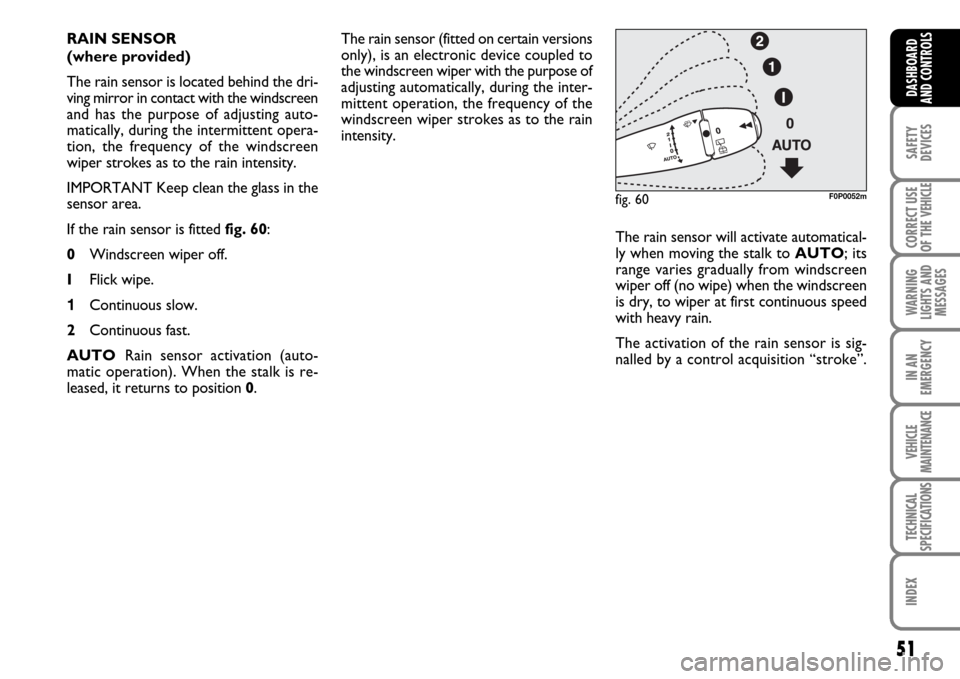
If the rain sensor is fitted fig. 60:
0Windscreen wiper off.
IFlick wipe.
1Continuous slow.
2Continuous fast.
AUTORain sensor activation (auto-
matic operation). When the stalk is re-
leased, it returns to position 0.
fig. 60F0P0052m
Page 69 of 210
68
SAFETY
DEVICES
CORRECT USE
OF THE
VEHICLE
WARNING
LIGHTS AND
MESSAGES
IN AN
EMERGENCY
VEHICLE
MAINTENANCE
TECHNICAL
SPECIFICATIONS
INDEX
DASHBOARD
AND
CONTROLS
IMPORTANT Do not use the ashtray as
waste paper basket: it might set on fire in
contact with cigarette stubs.
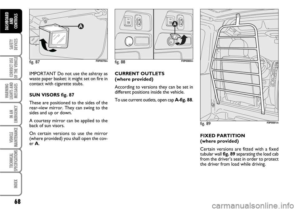
SUN VISORS fig. 87
These are positioned to the sides of the
rear-view mirror. They can swing to the
sides and up or down.
A courtesy mirror can be applied to the
back of sun visors.
On certain versions to use the mirror
(where provided) you shall open the cov-
er A.
fig. 87F0P0079mfig. 88F0P0080m
fig. 89F0P0081m
CURRENT OUTLETS
(where provided)
According to versions they can be set in
different positions inside the vehicle.
To use current outlets, open cap A-fig. 88.
FIXED PARTITION
(where provided)
Certain versions are fitted with a fixed
tubular wall fig. 89separating the load cab
from the driver’s seat in order to protect
the driver from load while driving.