seats FIAT SCUDO 2008 2.G Owners Manual
[x] Cancel search | Manufacturer: FIAT, Model Year: 2008, Model line: SCUDO, Model: FIAT SCUDO 2008 2.GPages: 210, PDF Size: 3.32 MB
Page 5 of 210
4
SAFETY
DEVICES
CORRECT USE
OF THE
VEHICLE
WARNING
LIGHTS AND
MESSAGES
IN AN
EMERGENCY
VEHICLE
MAINTENANCE
TECHNICAL
SPECIFICATIONS
INDEX
DASHBOARD
AND CONTROLSDASHBOARD ...................................................................... 5
SYMBOLS ............................................................................... 6
THE FIAT CODE SYSTEM ................................................. 6
THE KEYS .............................................................................. 7
ALARM ................................................................................... 10
IGNITION DEVICE ............................................................. 12
INSTRUMENT PANEL ........................................................ 13
INSTRUMENTS .................................................................... 14
DISPLAY.................................................................................. 15
MAINTENANCE INDICATOR ........................................ 16
TRIP COMPUTER................................................................. 17
FRONT SEATS ..................................................................... 17
REAR SEATS .......................................................................... 20
SEAT ARRANGEMENTS .................................................... 22
HEAD RESTRAINTS ........................................................... 23
STEERING WHEEL .............................................................. 24
REARVIEW MIRRORS ........................................................ 25
HEATING AND VENTILATION ..................................... 27
MANUAL CLIMATE CONTROL SYSTEM .................... 31
AUTOMATIC TWO-ZONE CLIMATE
CONTROL SYSTEM ........................................................... 37
AUTOMATIC THREE-ZONE CLIMATE
CONTROL SYSTEM ........................................................... 45
EXTERNAL LIGHTS ............................................................ 47WINDOW WASHING ...................................................... 50
CRUISE CONTROL SPEED REGULATOR.................... 54
“LIMIT” SPEED RESTRICTOR .......................................... 57
CEILING LIGHTS ................................................................. 60
CONTROLS .......................................................................... 61
FUEL CUT-OFF SWITCH .................................................. 64
INTERIOR EQUIPMENT..................................................... 65
DOORS .................................................................................. 69
SLIDING LUGGAGE COVER............................................ 73
POWER WINDOWS/WINDOW WINDERS .............. 74
BONNET ............................................................................... 76
ROOF RACK/SKI RACK .................................................... 77
PNEUMATIC SUSPENSIONS............................................. 78
LOAD RECOMMENDATIONS......................................... 79
HEADLIGHTS ....................................................................... 81
ABS SYSTEM ......................................................................... 82
ESP SYSTEM .......................................................................... 84
EOBD SYSTEM ..................................................................... 87
PARKING SENSORS ........................................................... 88
SOUND SYSTEM ................................................................. 89
ACCESSORIES PURCHASED BY THE OWNER ......... 90
AT THE FILLING STATION ............................................. 91
PROTECTING THE ENVIRONMENT ........................... 92
D D
A A
S S
H H
B B
O O
A A
R R
D D
A A
N N
D D
C C
O O
N N
T T
R R
O O
L L
S S
Page 16 of 210
15
SAFETY
DEVICES
CORRECT USE
OF THE
VEHICLE
WARNING
LIGHTS AND
MESSAGES
IN AN
EMERGENCY
VEHICLE
MAINTENANCE
TECHNICAL
SPECIFICATIONS
INDEX
DASHBOARD
AND CONTROLS
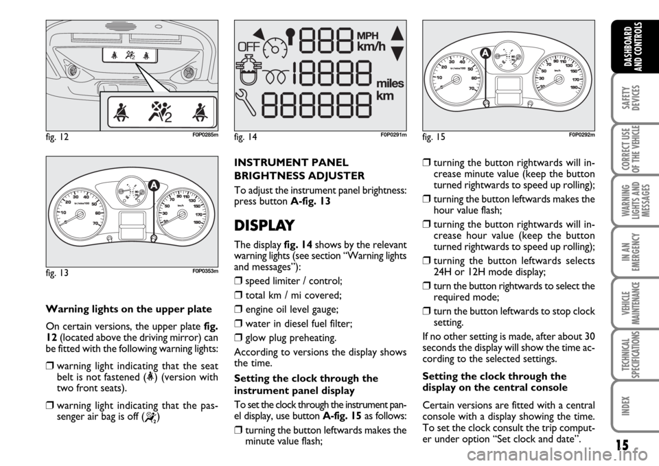
Warning lights on the upper plate
On certain versions, the upper plate fig.
12(located above the driving mirror) can
be fitted with the following warning lights:
❒warning light indicating that the seat
belt is not fastened (<) (version with
two front seats).
❒warning light indicating that the pas-
senger air bag is off (
“)
fig. 12F0P0285m
INSTRUMENT PANEL
BRIGHTNESS ADJUSTER
To adjust the instrument panel brightness:
press button A-fig. 13
DISPLAY
The display fig. 14shows by the relevant
warning lights (see section “Warning lights
and messages”):
❒speed limiter / control;
❒total km / mi covered;
❒engine oil level gauge;
❒water in diesel fuel filter;
❒glow plug preheating.
According to versions the display shows
the time.
Setting the clock through the
instrument panel display
To set the clock through the instrument pan-
el display, use button A-fig. 15as follows:
❒turning the button leftwards makes the
minute value flash;
❒turning the button rightwards will in-
crease minute value (keep the button
turned rightwards to speed up rolling);
❒turning the button leftwards makes the
hour value flash;
❒turning the button rightwards will in-
crease hour value (keep the button
turned rightwards to speed up rolling);
❒turning the button leftwards selects
24H or 12H mode display;
❒turn the button rightwards to select the
required mode;
❒turn the button leftwards to stop clock
setting.
If no other setting is made, after about 30
seconds the display will show the time ac-
cording to the selected settings.
Setting the clock through the
display on the central console
Certain versions are fitted with a central
console with a display showing the time.
To set the clock consult the trip comput-
er under option “Set clock and date”.
fig. 14F0P0291mfig. 15
1/2
F0P0292m
fig. 13
1/2
F0P0353m
Page 18 of 210
17
SAFETY
DEVICES
CORRECT USE
OF THE
VEHICLE
WARNING
LIGHTS AND
MESSAGES
IN AN
EMERGENCY
VEHICLE
MAINTENANCE
TECHNICAL
SPECIFICATIONS
INDEX
DASHBOARD
AND CONTROLS
Distance to cover
This value shows the distance to be cov-
ered yet, under active navigation condi-
tion.
Trip distance
This value shows the distance covered
from the start of the journey, after reset-
ting (Reset).
Average consumption
This value shows the average consump-
tion from the start of the journey, after
resetting (Reset).
Average speed
This value shows the vehicle average
speed calculated from the start of the
journey, after resetting (Reset).
TRIP COMPUTER
The trip computer enables to display in se-
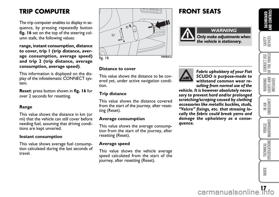
quence, by pressing repeatedly button
fig. 16set on the top of the steering col-
umn stalk, the following values:
range, instant consumption, distance
to cover, trip 1 (trip distance, aver-
age consumption, average speed)
and trip 2 (trip distance, average
consumption, average speed).
This information is displayed on the dis-
play of the infotelematic CONNECT sys-
tem.
Reset: press button shown in fig. 16for
over 2 seconds for resetting.
Range
This value shows the distance in km (or
mi) that the vehicle can still cover before
needing fuel, assuming that driving condi-
tions are kept unvaried.
Instant consumption
This value shows average fuel consump-
tion calculated during the last seconds of
travel.
fig. 16F0P0041m
FRONT SEATS
Only make adjustments when
the vehicle is stationary.
WARNING
Fabric upholstery of your Fiat
SCUDO is purpose-made to
withstand common wear re-
sulting from normal use of the
vehicle. It is however absolutely neces-
sary to prevent hard and/or prolonged
scratching/scraping caused by clothing
accessories like metallic buckles, studs,
“Velcro” fixings, etc. that stressing lo-
cally the fabric could break yarns and
damage the upholstery as a conse-
quence.
Page 19 of 210
18
SAFETY
DEVICES
CORRECT USE
OF THE
VEHICLE
WARNING
LIGHTS AND
MESSAGES
IN AN
EMERGENCY
VEHICLE
MAINTENANCE
TECHNICAL
SPECIFICATIONS
INDEX
DASHBOARD
AND
CONTROLS
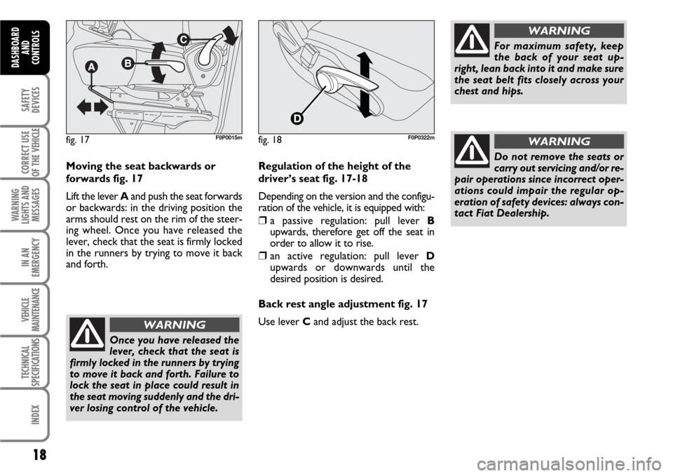
Moving the seat backwards or
forwards fig. 17
Lift the lever Aand push the seat forwards
or backwards: in the driving position the
arms should rest on the rim of the steer-
ing wheel. Once you have released the
lever, check that the seat is firmly locked
in the runners by trying to move it back
and forth.
Once you have released the
lever, check that the seat is
firmly locked in the runners by trying
to move it back and forth. Failure to
lock the seat in place could result in
the seat moving suddenly and the dri-
ver losing control of the vehicle.
WARNING
For maximum safety, keep
the back of your seat up-
right, lean back into it and make sure
the seat belt fits closely across your
chest and hips.
WARNING
Regulation of the height of the
driver’s seat fig. 17-18
Depending on the version and the configu-
ration of the vehicle, it is equipped with:
❒a passive regulation: pull lever B
upwards, therefore get off the seat in
order to allow it to rise.
❒an active regulation: pull lever D
upwards or downwards until the
desired position is desired.
Back rest angle adjustment fig. 17
Use lever C and adjust the back rest.
Do not remove the seats or
carry out servicing and/or re-
pair operations since incorrect oper-
ations could impair the regular op-
eration of safety devices: always con-
tact Fiat Dealership.
WARNINGfig. 17F0P0015mfig. 18F0P0322m
Page 20 of 210
19
SAFETY
DEVICES
CORRECT USE
OF THE
VEHICLE
WARNING
LIGHTS AND
MESSAGES
IN AN
EMERGENCY
VEHICLE
MAINTENANCE
TECHNICAL
SPECIFICATIONS
INDEX
DASHBOARD
AND CONTROLS
fig. 18/aF0P0016m
fig. 19
AB
F0P0017m
fig. 20F0P0018m
fig. 21F0P0019m
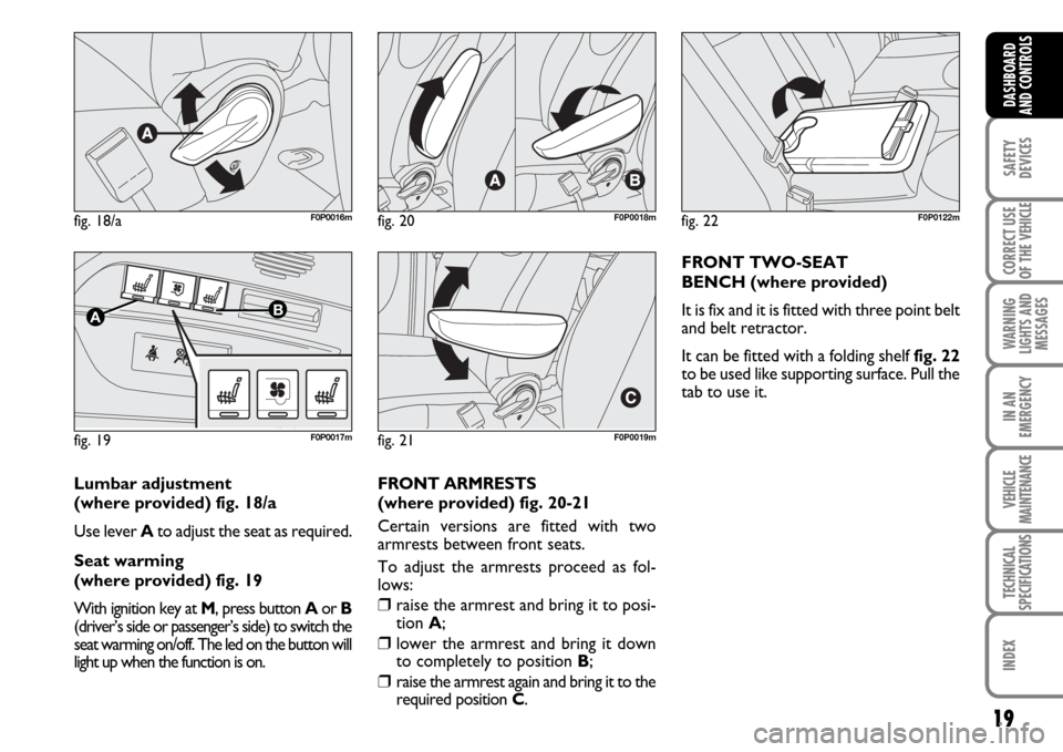
Lumbar adjustment
(where provided) fig. 18/a
Use lever Ato adjust the seat as required.
Seat warming
(where provided) fig. 19
With ignition key at M, press button Aor B
(driver’s side or passenger’s side) to switch the
seat warming on/off. The led on the button will
light up when the function is on.FRONT ARMRESTS
(where provided) fig. 20-21
Certain versions are fitted with two
armrests between front seats.
To adjust the armrests proceed as fol-
lows:
❒raise the armrest and bring it to posi-
tion A;
❒lower the armrest and bring it down
to completely to position B;
❒raise the armrest again and bring it to the
required position C.
fig. 22F0P0122m
FRONT TWO-SEAT
BENCH (where provided)
It is fix and it is fitted with three point belt
and belt retractor.
It can be fitted with a folding shelf fig. 22
to be used like supporting surface. Pull the
tab to use it.
Page 21 of 210
20
SAFETY
DEVICES
CORRECT USE
OF THE
VEHICLE
WARNING
LIGHTS AND
MESSAGES
IN AN
EMERGENCY
VEHICLE
MAINTENANCE
TECHNICAL
SPECIFICATIONS
INDEX
DASHBOARD
AND
CONTROLS
FOLDING, REMOVING AND
REFITTING THE REAR BENCH
SEAT
To remove and then to re-
fit the bench seat, keep
the back rest firmly lowered and
flattened against the cushion to
prevent any contact between the
seat articulation mechanisms.
WARNING
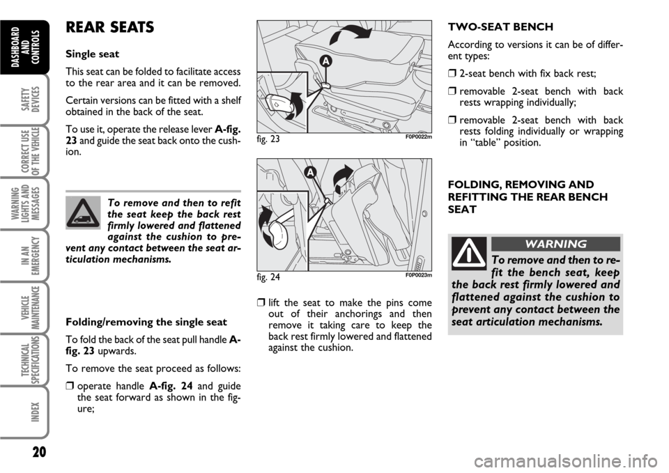
REAR SEATS
Single seat
This seat can be folded to facilitate access
to the rear area and it can be removed.
Certain versions can be fitted with a shelf
obtained in the back of the seat.
To use it, operate the release lever A-fig.
23and guide the seat back onto the cush-
ion.
Folding/removing the single seat
To fold the back of the seat pull handle A-
fig. 23upwards.
To remove the seat proceed as follows:
❒operate handle A-fig. 24and guide
the seat forward as shown in the fig-
ure;
❒lift the seat to make the pins come
out of their anchorings and then
remove it taking care to keep the
back rest firmly lowered and flattened
against the cushion.
fig. 23F0P0022m
fig. 24F0P0023m
To remove and then to refit
the seat keep the back rest
firmly lowered and flattened
against the cushion to pre-
vent any contact between the seat ar-
ticulation mechanisms.
TWO-SEAT BENCH
According to versions it can be of differ-
ent types:
❒2-seat bench with fix back rest;
❒removable 2-seat bench with back
rests wrapping individually;
❒removable 2-seat bench with back
rests folding individually or wrapping
in “table” position.
Page 22 of 210
21
SAFETY
DEVICES
CORRECT USE
OF THE
VEHICLE
WARNING
LIGHTS AND
MESSAGES
IN AN
EMERGENCY
VEHICLE
MAINTENANCE
TECHNICAL
SPECIFICATIONS
INDEX
DASHBOARD
AND CONTROLS
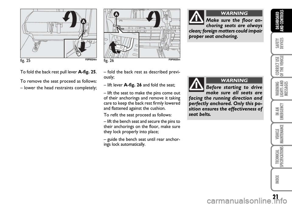
To fold the back rest pull lever A-fig. 25.
To remove the seat proceed as follows:
– lower the head restraints completely;
fig. 25F0P0024mfig. 26F0P0025m
– fold the back rest as described previ-
ously;
– lift leverA-fig. 26and fold the seat;
– lift the seat to make the pins come out
of their anchorings and remove it taking
care to keep the back rest firmly lowered
and flattened against the cushion.
To refit the seat proceed as follows:
– lift the bench seat and secure the pins to
their anchorings on the floor, make sure
they lock properly into place;
– guide the bench seat until rear anchor-
ings lock automatically.
Make sure the floor an-
choring seats are always
clean; foreign matters could impair
proper seat anchoring.
WARNING
Before starting to drive
make sure all seats are
facing the running direction and
perfectly anchored. Only this po-
sition ensures the effectiveness of
seat belts.
WARNING
Page 23 of 210
22
SAFETY
DEVICES
CORRECT USE
OF THE
VEHICLE
WARNING
LIGHTS AND
MESSAGES
IN AN
EMERGENCY
VEHICLE
MAINTENANCE
TECHNICAL
SPECIFICATIONS
INDEX
DASHBOARD
AND
CONTROLS
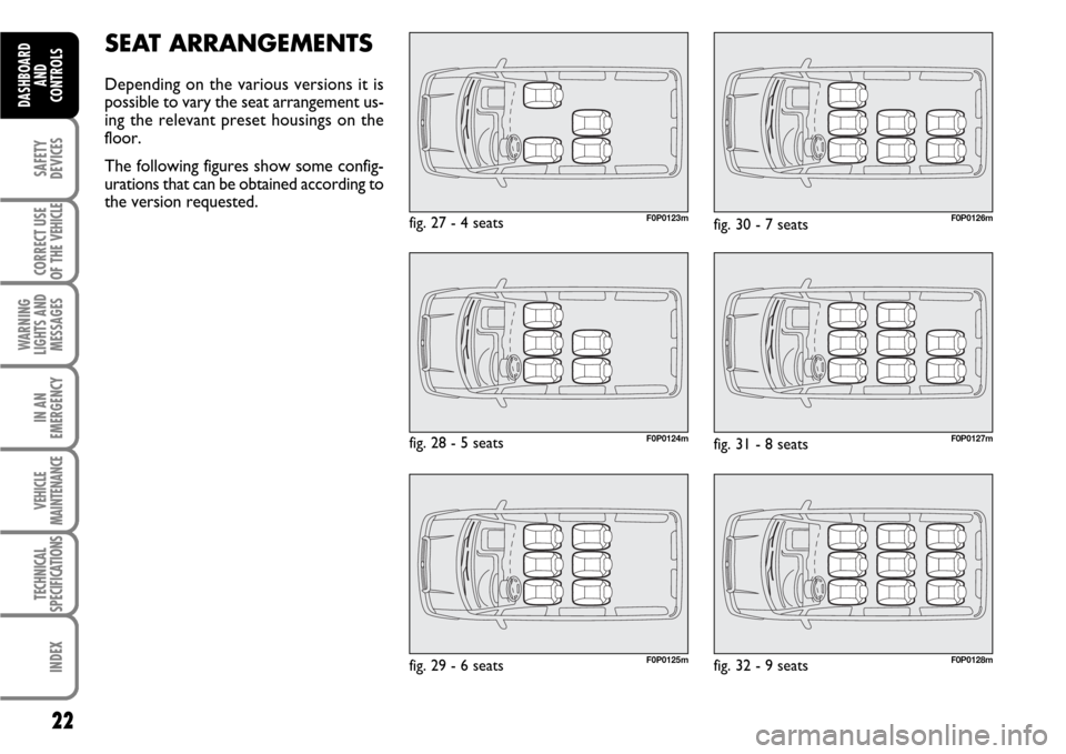
SEAT ARRANGEMENTS
Depending on the various versions it is
possible to vary the seat arrangement us-
ing the relevant preset housings on the
floor.
The following figures show some config-
urations that can be obtained according to
the version requested.
F0P0123mfig. 27 - 4 seats
F0P0124m
F0P0125m
fig. 28 - 5 seats
fig. 29 - 6 seats
F0P0126m
F0P0127m
F0P0128m
fig. 30 - 7 seats
fig. 31 - 8 seats
fig. 32 - 9 seats
Page 28 of 210
27
SAFETY
DEVICES
CORRECT USE
OF THE
VEHICLE
WARNING
LIGHTS AND
MESSAGES
IN AN
EMERGENCY
VEHICLE
MAINTENANCE
TECHNICAL
SPECIFICATIONS
INDEX
DASHBOARD
AND CONTROLS
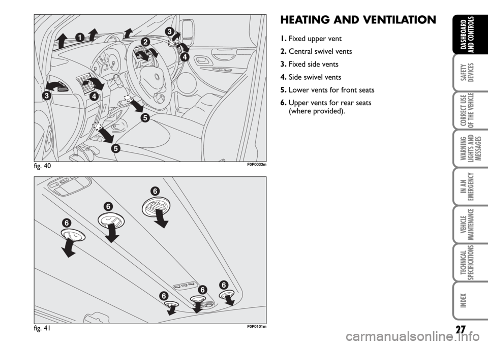
HEATING AND VENTILATION
1.Fixed upper vent
2.Central swivel vents
3.Fixed side vents
4.Side swivel vents
5. Lower vents for front seats
6.Upper vents for rear seats
(where provided).
fig. 40F0P0033m
fig. 41F0P0101m
Page 72 of 210
71
SAFETY
DEVICES
CORRECT USE
OF THE
VEHICLE
WARNING
LIGHTS AND
MESSAGES
IN AN
EMERGENCY
VEHICLE
MAINTENANCE
TECHNICAL
SPECIFICATIONS
INDEX
DASHBOARD
AND CONTROLS
fig. 94F0P0087mfig. 95F0P0602mfig. 96F0P0293m
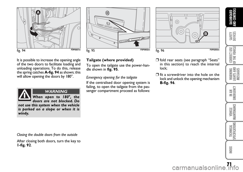
It is possible to increase the opening angle
of the two doors to facilitate loading and
unloading operations. To do this, release
the spring catches A-fig. 94as shown; this
will allow opening the doors by 180°.
When open to 180°, the
doors are not blocked. Do
not use this system when the vehicle
is parked on a slope or when it is
windy.
WARNING
Closing the double doors from the outside
After closing both doors, turn the key to
1-fig. 92.Tailgate (where provided)
To open the tailgate use the power-han-
dle shown in fig. 95.
Emergency opening for the tailgate
If the centralised door opening system is
failing, to open the tailgate from the pas-
senger compartment proceed as follows:
❒fold rear seats (see paragraph “Seats”
in this section) to reach the internal
lock;
❒fit a screwdriver into the hole on the
lock and unlock the opening mechanism
B-fig. 96.