sensor FIAT STILO 2006 1.G Owners Manual
[x] Cancel search | Manufacturer: FIAT, Model Year: 2006, Model line: STILO, Model: FIAT STILO 2006 1.GPages: 274, PDF Size: 4.76 MB
Page 5 of 274
4
SAFETY
DEVICES
CORRECT USE
OF THE CAR
WARNING
LIGHTS AND
MESSAGES
IN AN
EMERGENCY
CAR
MAINTENANCE
TECHNICAL
SPECIFICATIONS
INDEX
DASHBOARD
AND CONTROLSDASHBOARD ........................................................................ 5
INSTRUMENT PANEL ......................................................... 6
SYMBOLS ................................................................................. 8
THE FIAT CODE SYSTEM ................................................... 8
THE KEYS ................................................................................ 10
ALARM ..................................................................................... 17
IGNITION SWITCH.............................................................. 20
INSTRUMENTS ....................................................................... 21
MULTIFUNCTION DISPLAY ............................................. 23
TRIP COMPUTER ................................................................. 34
SEATS ........................................................................................ 37
HEAD RESTRAINTS .............................................................. 41
STEERING WHEEL ............................................................... 42
REARVIEW MIRRORS ........................................................... 43
HEATING/CLIMATE CONTROL SYSTEM .................... 44
HEATING AND VENTILATION ....................................... 46
MANUAL CLIMATE CONTROL SYSTEM .................... 48
AUTOMATIC TWO-ZONE
CLIMATE CONTROL SYSTEM ......................................... 51
EXTERNAL LIGHTS .............................................................. 57
WINDOW WASHING......................................................... 60CRUISE CONTROL ............................................................. 64
CEILING LIGHTS .................................................................. 67
CONTROLS ........................................................................... 68
INTERIOR FITTINGS ............................................................ 70
“SKYWINDOW”(BLADE SUNROOF) ........................... 74
DOORS .................................................................................... 79
POWER WINDOWS ........................................................... 80
BOOT ........................................................................................ 81
BONNET .................................................................................. 92
ROOF RACK/SKI RACK ..................................................... 93
HEADLIGHTS .......................................................................... 94
ABS SYSTEM ........................................................................... 95
ESP SYSTEM ............................................................................ 97
EOBD SYSTEM ....................................................................... 99
SOUND SYSTEM .................................................................... 100
ACCESSORIES PURCHASED BY THE OWNER ......... 101
“DUALDRIVE” ELECTRIC POWER
STEERING SYSTEM .............................................................. 102
PARKING SENSORS ............................................................ 103
AT THE FILLING STATION .............................................. 105
PROTECTING THE ENVIRONMENT ............................ 108
D D
A A
S S
H H
B B
O O
A A
R R
D D
A A
N N
D D
C C
O O
N N
T T
R R
O O
L L
S S
Page 14 of 274
13
SAFETY
DEVICES
CORRECT USE
OF THE CAR
WARNING
LIGHTS AND
MESSAGES
IN AN
EMERGENCY
CAR
MAINTENANCE
TECHNICAL
SPECIFICATIONS
INDEX
DASHBOARD
AND CONTROLS
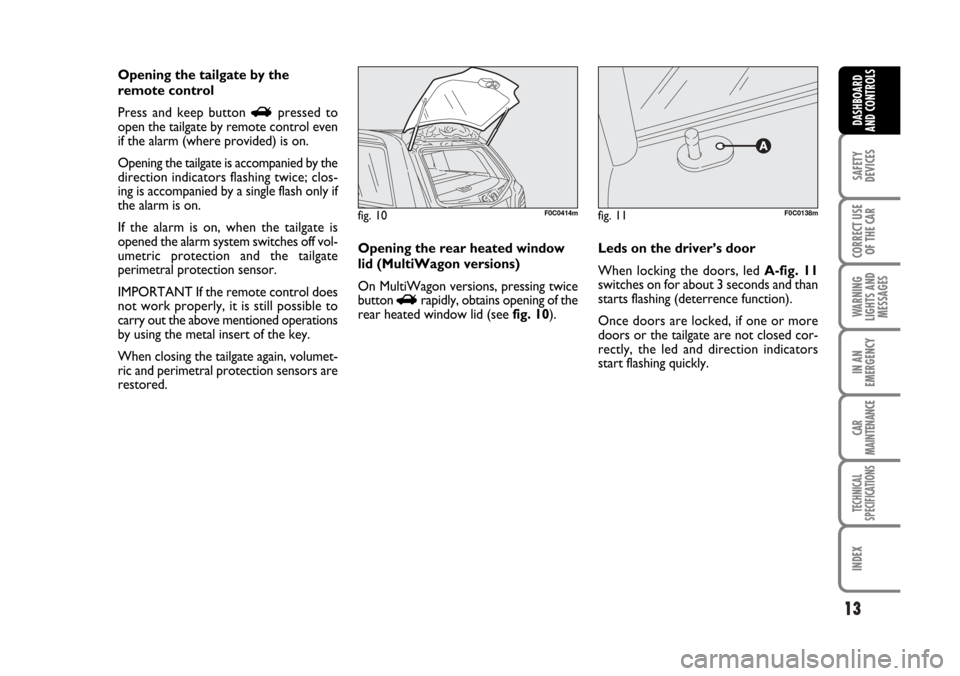
Opening the tailgate by the
remote control
Press and keep button
Rpressed to
open the tailgate by remote control even
if the alarm (where provided) is on.
Opening the tailgate is accompanied by the
direction indicators flashing twice; clos-
ing is accompanied by a single flash only if
the alarm is on.
If the alarm is on, when the tailgate is
opened the alarm system switches off vol-
umetric protection and the tailgate
perimetral protection sensor.
IMPORTANT If the remote control does
not work properly, it is still possible to
carry out the above mentioned operations
by using the metal insert of the key.
When closing the tailgate again, volumet-
ric and perimetral protection sensors are
restored. Leds on the driver’s door
When locking the doors, led A-fig. 11
switches on for about 3 seconds and than
starts flashing (deterrence function).
Once doors are locked, if one or more
doors or the tailgate are not closed cor-
rectly, the led and direction indicators
start flashing quickly.
fig. 11F0C0138m
Opening the rear heated window
lid (MultiWagon versions)
On MultiWagon versions, pressing twice
button
Rrapidly, obtains opening of the
rear heated window lid (see fig. 10).
fig. 10F0C0414m
Page 18 of 274

17
SAFETY
DEVICES
CORRECT USE
OF THE CAR
WARNING
LIGHTS AND
MESSAGES
IN AN
EMERGENCY
CAR
MAINTENANCE
TECHNICAL
SPECIFICATIONS
INDEX
DASHBOARD
AND CONTROLS
ALARM
(where provided)
The alarm function is provided in addition
to all remote control functions previous-
ly described and it is controlled by the re-
ceiver located under the dashboard, next
to the fuse box.
WHEN THE ALARM IS
TRIGGERED
The alarm comes into action in the fol-
lowing cases:
❒ unlawful opening of one of the doors,
bonnet or boot (perimetral protec-
tion);
❒attempt to start the engine (turning the
ignition key to MAR);
❒ battery cable cutting;
❒ presence of moving bodies in the pas-
senger’s compartment (volumetric pro-
tection);
❒ abnormal raising/sloping of the car. Depending on the markets, the cutting in
of the alarm causes operation of the siren
and direction indicators (for about 26 sec-
onds). The ways of operating and the num-
ber of cycles may vary depending on the
markets.
A maximum number of sound/sight cycles
is however envisaged.
Volumetric and anti-raising protections
can be cut off by operating the front ceil-
ing light controls (see paragraphs “Volu-
metric protection sensors” and “Anti-rais-
ing sensor” on the following pages).
IMPORTANT The engine immobiliser
function is guaranteed by the Fiat CODE
system, which is automatically activated
when the ignition key is removed.HOW TO ACTIVATE THE
ALARM
With the doors, bonnet and boot shut and
the ignition key in the STOPposition or
with the key removed, point the key with
remote control in the direction of the car,
then press and release the button
Á.
With the exception of certain markets,
the system sounds a “beep” and the doors
are locked.
Engagement of the alarm is preceded by
a self-diagnostic test. If a fault is detected
the system sounds a further warning
“beep” and the display shows the relevant
message (see section “Warning lights and
messages”).
In this case, switch the alarm system off by
pressing button
Ë, check that the doors,
bonnet and tailgate are properly shut, then
switch the alarm on again by pressing but-
ton
Á.
Otherwise, the door, bonnet or tailgate
that is not shut properly will be excluded
from the alarm system control.
Page 19 of 274
18
SAFETY
DEVICES
CORRECT USE
OF THE CAR
WARNING
LIGHTS AND
MESSAGES
IN AN
EMERGENCY
CAR
MAINTENANCE
TECHNICAL
SPECIFICATIONS
INDEX
DASHBOARD
AND CONTROLS
If the doors, bonnet and boot are shut
correctly and the control signal is repeat-
ed, the system self-diagnostics has de-
tected a system operating fault. It is there-
fore necessary to contact Fiat Dealership.
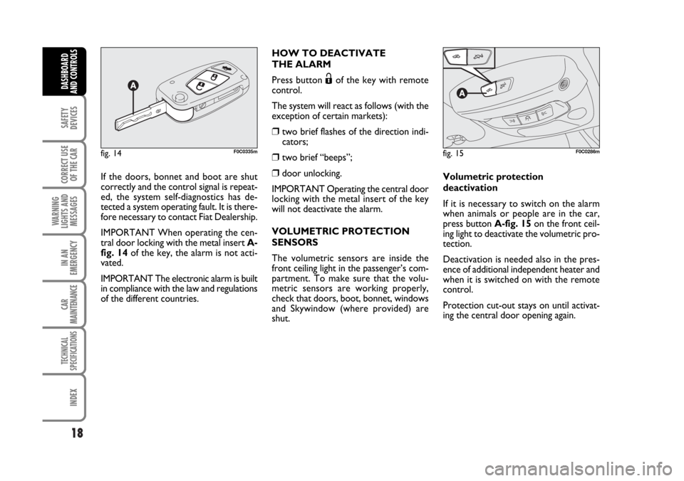
IMPORTANT When operating the cen-
tral door locking with the metal insert A-
fig. 14of the key, the alarm is not acti-
vated.
IMPORTANT The electronic alarm is built
in compliance with the law and regulations
of the different countries.HOW TO DEACTIVATE
THE ALARM
Press button
Ëof the key with remote
control.
The system will react as follows (with the
exception of certain markets):
❒ two brief flashes of the direction indi-
cators;
❒ two brief “beeps”;
❒door unlocking.
IMPORTANT Operating the central door
locking with the metal insert of the key
will not deactivate the alarm.
VOLUMETRIC PROTECTION
SENSORS
The volumetric sensors are inside the
front ceiling light in the passenger’s com-
partment. To make sure that the volu-
metric sensors are working properly,
check that doors, boot, bonnet, windows
and Skywindow (where provided) are
shut.Volumetric protection
deactivation
If it is necessary to switch on the alarm
when animals or people are in the car,
press button A-fig. 15 on the front ceil-
ing light to deactivate the volumetric pro-
tection.
Deactivation is needed also in the pres-
ence of additional independent heater and
when it is switched on with the remote
control.
Protection cut-out stays on until activat-
ing the central door opening again.
fig. 14F0C0335mfig. 15F0C0286m
Page 20 of 274
19
SAFETY
DEVICES
CORRECT USE
OF THE CAR
WARNING
LIGHTS AND
MESSAGES
IN AN
EMERGENCY
CAR
MAINTENANCE
TECHNICAL
SPECIFICATIONS
INDEX
DASHBOARD
AND CONTROLS
ANTI-RAISING SENSOR
The anti-raising sensor detects any ab-
normal car raising/sloping, even partial
(e.g.: attempt to remove a wheel).
This sensor can detect the smallest car
sideslip angle changes, both longitudinally
and transversally.
Sideslip angle changes lower than 0.5°/min.
(e.g.: slow tyre flattening) are not consid-
ered.
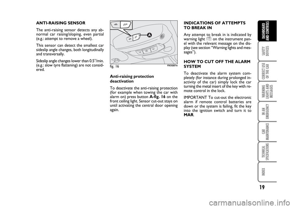
Anti-raising protection
deactivation
To deactivate the anti-raising protection
(for example when towing the car with
alarm on) press button A-fig. 16 on the
front ceiling light. Sensor cut-out stays on
until activating the central door opening
again.INDICATIONS OF ATTEMPTS
TO BREAK IN
Any attempt to break in is indicated by
warning light
Yon the instrument pan-
el with the relevant message on the dis-
play (see section “Warning lights and mes-
sages”).
HOW TO CUT OFF THE ALARM
SYSTEM
To deactivate the alarm system com-
pletely (for instance during prolonged in-
activity of the car) simply lock the car
turning the metal insert of the key with re-
mote control in the lock.
IMPORTANT To cut-out the electronic
alarm if remote control batteries are
down or the system is failing, fit the key
into the ignition switch and turn it to
MAR.
fig. 16F0C0287m
Page 27 of 274
26
SAFETY
DEVICES
CORRECT USE
OF THE CAR
WARNING
LIGHTS AND
MESSAGES
IN AN
EMERGENCY
CAR
MAINTENANCE
TECHNICAL
SPECIFICATIONS
INDEX
DASHBOARD
AND CONTROLS
Day
YearMonth
Español
English
Portuges
Deutsch
Français
Italiano
EXIT MENUTRIP B DATASET TIME
SET DATE
SEE RADIO
KEY
AUTOCLOSE
UNITS
LANGUAGE
BUZZER VOLUME BUTTON VOL. BELT BUZZER SERVICESPEED BEEP
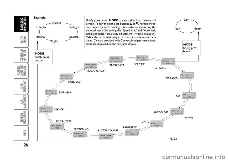
Briefly press button MODEto start surfing from the standard
screen. To surf the menu use buttons Õor Ô. For safety rea-
sons, when the car is running, it is possible to access only the
reduced menu (for setting the “Speed limit” and “Automatic
headlight sensor sensitivity adjustment” (where provided).
When the car is stationary access to the whole menu is en-
abled. On cars provided with Connect/Navigator many func-
tions are displayed on the navigator display.
MODE
briefly press
button
MODE
briefly press
button
Example:
fig. 22
HEADL. SENSOR
F0C2369g
Page 28 of 274

27
SAFETY
DEVICES
CORRECT USE
OF THE CAR
WARNING
LIGHTS AND
MESSAGES
IN AN
EMERGENCY
CAR
MAINTENANCE
TECHNICAL
SPECIFICATIONS
INDEX
DASHBOARD
AND CONTROLS
Speed limit (Speed Beep)
With this function it is possible to set the
car speed limit (km/h or mph); when this
limit is exceeded the driver is immediate-
ly alerted (see section “Warning lights and
messages”).
To set the speed limit, proceed as follows:
– briefly press button MODE, the display
will show wording (Speed Beep);
– press button
Õor Ôto select activa-
tion (On) or deactivation (Off) of the
speed limit;
– if selecting (On), press button
Õor Ôto select the required speed limit and then
press MODEto confirm.
NoteThe possible setting is between 30
and 250 km/h, or between 20 and 155
mph depending on the unit set previous-
ly (see paragraph “Distance unit (Dis-
tances)” described later. Every press on
button
Õ/Ôincreases/decreases by 5
units. Keeping the button Õ/Ôpressed
obtains the automatic fast increase or de-
crease. When you are near the required
setting complete adjustment by single
presses.
– briefly press button MODEto go back
to the menu screen or press the button
for long to go back to the standard screen
without storing settings.To abort the setting, proceed as follows:
– briefly press button MODE: (On) will
flash on the display;
– press button
Ô: (Off) will flash on the
display;
– briefly press button MODEto go back
to the menu screen or press the button
for long to go back to the standard screen
without storing settings.Automatic headlight sensor
sensitivity adjustment
(Headl. sensor) (where provided)
With this function it is possible to adjust
the light sensor sensitivity according to 3
levels (level 1 = min. level, level 2 = av-
erage level, level 3 = max. level); the high-
er the sensitivity is, the lower is the ex-
ternal light intensity required to switch on
the lights.
This operation can be performed also with
the car moving.
To set the light level required, proceed as
follows:
– briefly press button MODE, the previ-
ously set level will flash on the display;
– press button
Õor Ôto select the re-
quired level;
– briefly press button MODEto go back
to the menu screen or press the button
for long to go back to the standard screen
without storing settings.
Page 52 of 274
51
SAFETY
DEVICES
CORRECT USE
OF THE CAR
WARNING
LIGHTS AND
MESSAGES
IN AN
EMERGENCY
CAR
MAINTENANCE
TECHNICAL
SPECIFICATIONS
INDEX
DASHBOARD
AND CONTROLS
F0C0381mfig. 46
AUTOMATIC
TWO-ZONE CLIMATE
CONTROL SYSTEM
(where provided)
Description
The car is fitted with a two-zone climate
control system which makes it possible to
separately adjust the air temperature on
the driver’s side and on the passenger’s
side.
The system is fitted with the AQS func-
tion (Air Quality System) that turns on in-
side air recirculation automatically when
it detects the presence of outside pollut-
ed air (for example when driving in the
city, queues and tunnels).
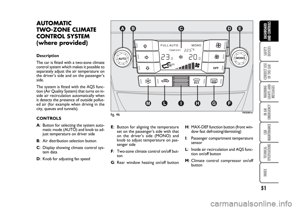
CONTROLS
A: Button for selecting the system auto-
matic mode (AUTO) and knob to ad-
just temperature on driver side
B: Air distribution selection button
C: Display showing climate control sys-
tem data
D: Knob for adjusting fan speedE: Button for aligning the temperature
set on the passenger’s side with that
on the driver’s side (MONO) and
knob to adjust temperature on pas-
senger side
F: Two-zone climate control on/off but-
ton
G: Rear window heating on/off buttonH: MAX-DEF function button (front win-
dow fast defrosting/demisting)
I: Passenger compartment temperature
sensor
L: Inside air recirculation and AQS func-
tion on/off button
M: Climate control compressor on/off
button
Page 60 of 274
59
SAFETY
DEVICES
CORRECT USE
OF THE CAR
WARNING
LIGHTS AND
MESSAGES
IN AN
EMERGENCY
CAR
MAINTENANCE
TECHNICAL
SPECIFICATIONS
INDEX
DASHBOARD
AND CONTROLS
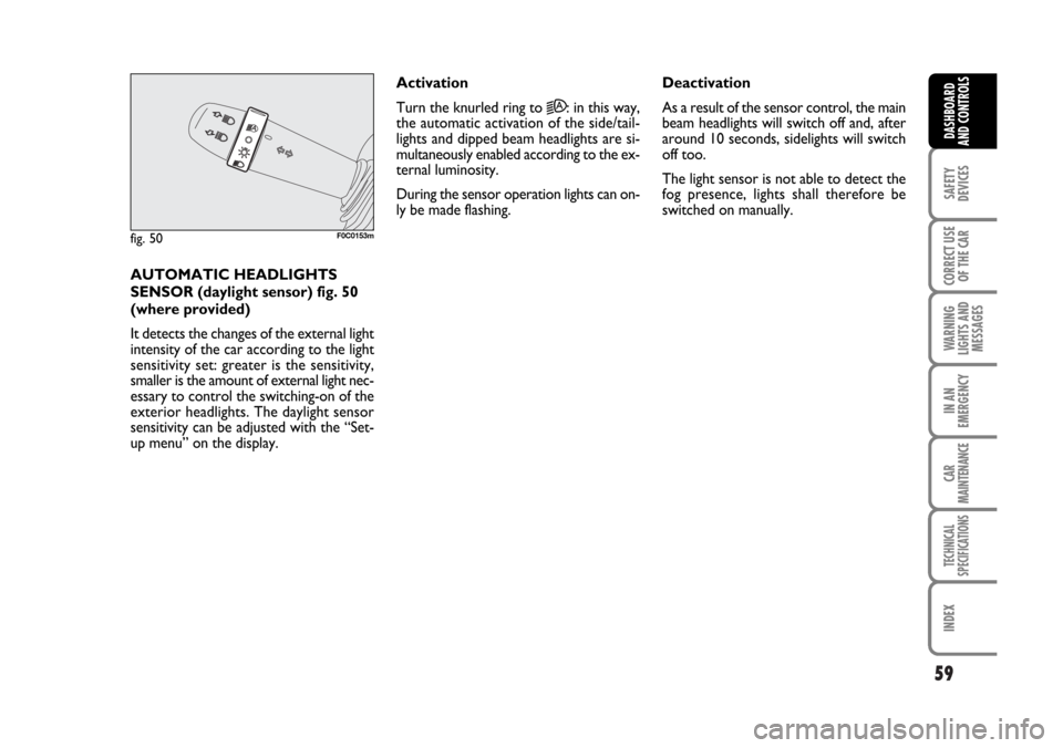
AUTOMATIC HEADLIGHTS
SENSOR (daylight sensor) fig. 50
(where provided)
It detects the changes of the external light
intensity of the car according to the light
sensitivity set: greater is the sensitivity,
smaller is the amount of external light nec-
essary to control the switching-on of the
exterior headlights. The daylight sensor
sensitivity can be adjusted with the “Set-
up menu” on the display.Activation
Turn the knurled ring to
2A: in this way,
the automatic activation of the side/tail-
lights and dipped beam headlights are si-
multaneously enabled according to the ex-
ternal luminosity.
During the sensor operation lights can on-
ly be made flashing. Deactivation
As a result of the sensor control, the main
beam headlights will switch off and, after
around 10 seconds, sidelights will switch
off too.
The light sensor is not able to detect the
fog presence, lights shall therefore be
switched on manually.
fig. 50F0C0153m
Page 62 of 274
61
SAFETY
DEVICES
CORRECT USE
OF THE CAR
WARNING
LIGHTS AND
MESSAGES
IN AN
EMERGENCY
CAR
MAINTENANCE
TECHNICAL
SPECIFICATIONS
INDEX
DASHBOARD
AND CONTROLS
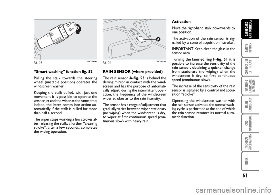
“Smart washing” function fig. 52
Pulling the stalk towards the steering
wheel (unstable position) operates the
windscreen washer.
Keeping the stalk pulled, with just one
movement it is possible to operate the
washer jet and the wiper at the same time;
indeed, the latter comes into action au-
tomatically if the stalk is pulled for more
than half a second.
The wiper stops working a few strokes af-
ter releasing the stalk; a further “cleaning
stroke”, after a few seconds, completes
the wiping operation.RAIN SENSOR (where provided)
The rain sensor A-fig. 53is behind the
driving mirror in contact with the wind-
screen and has the purpose of automati-
cally adjust, during the intermittent oper-
ation, the frequency of the windscreen
wiper strokes as to the rain intensity.
The sensor has a range of adjustment that
gradually varies between wiper stationary
(no wiping) when the windscreen is dry,
to wiper at first continuous speed (con-
tinuous slow) with heavy rain.Activation
Move the right-hand stalk downwards by
one position.
The activation of the rain sensor is sig-
nalled by a control acquisition “stroke”.
IMPORTANT Keep clean the glass in the
sensor area.
Turning the knurled ring F-fig. 51it is
possible to increase the sensitivity of the
rain sensor, obtaining a quicker change
from stationary (no wiping) when the
windscreen is dry, to first continuous
speed (continuous slow).
The increase of the sensitivity of the rain
sensor is signalled by a control and acqui-
sition “stroke”.
Operating the windscreen washer with
the rain sensor activated the normal wash-
ing cycle is performed at the end of which
the rain sensor resumes its normal auto-
matic function.
fig. 52F0C0049mfig. 53F0C0053m