wheel FIAT STRADA 2011 Owner handbook (in English)
[x] Cancel search | Manufacturer: FIAT, Model Year: 2011, Model line: STRADA, Model: FIAT STRADA 2011Pages: 195, PDF Size: 3.68 MB
Page 110 of 195
108
PARKING
Stop the engine, engage the
handbrake, engage 1st gear uphill or
reverse downhill and leave the
wheels steered towards the edge of
the road or the pavement. If the
vehicle is parked on a steep slope, it
is advisable to block the wheels with
a wedge or stone.
Do not leave the ignition key at
MAR because this drains the battery.
Always extract the key when getting
out of the vehicle.
Never leave children
alone in the unattended
vehicle.
WARNING
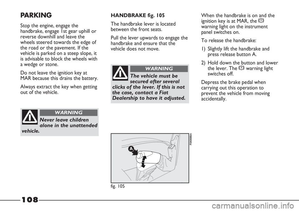
HANDBRAKE fig. 105
The handbrake lever is located
between the front seats.
Pull the lever upwards to engage the
handbrake and ensure that the
vehicle does not move.When the handbrake is on and the
ignition key is at MAR, the x
warning light on the instrument
panel switches on.
To release the handbrake:
1) Slightly lift the handbrake and
press release button A.
2) Hold down the button and lower
the lever. The xwarning light
switches off.
Depress the brake pedal when
carrying out this operation to
prevent the vehicle from moving
accidentally.
The vehicle must be
secured after several
clicks of the lever. If this is not
the case, contact a Fiat
Dealership to have it adjusted.
WARNING
fig. 105
F0X0086m
Page 111 of 195
109
SNOW TYRES
Fiat Dealerships will be happy to
provide advice concerning the most
suitable type of tyres for the
Customer’s requirements.
For the type of snow tyre to be
used, inflation pressures and the
specifications of the tyres, carefully
follow the instructions given in the
“Wheels” paragraph in the
“Technical Specifications” section.
The winter features of these tyres
are reduced considerably when the
tread depth is less than 4 mm. They
should be replaced in this case.
Due to snow tyre characteristics,
under normal conditions of use or
on long motorway journeys, the
performance of these tyres is lower
than that of standard tyres. Their
usage should therefore be restricted
in accordance with their type
approval.IMPORTANT When using snow
tyres with a maximum speed rating
lower than that of the vehicle
(increased by 5%), place a clearly
visible warning sign in the passenger
compartment warning other drivers
of the maximum speed rating of the
snow tyres used (as required by EC
directive).All four tyres should be
the same (brand and track) to
ensure greater safety when driving,
during braking and better
driveability.
Remember that it is inadvisable to
change the rotation direction of
tyres.
USING THE GEARBOX
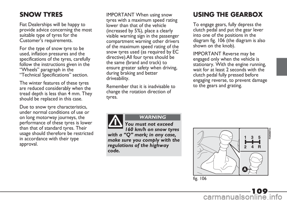
To engage gears, fully depress the
clutch pedal and put the gear lever
into one of the positions in the
diagram fig. 106 (the diagram is also
shown on the knob).
IMPORTANT Reverse may be
engaged only when the vehicle is
stationary. With the engine running,
wait for at least 2 seconds with the
clutch pedal fully pressed before
engaging reverse, to prevent damage
to the gears and grating.
You must not exceed
160 km/h on snow tyres
with a “Q” mark; in any case,
make sure you comply with the
regulations of the highway
code.
WARNING
fig. 106
F0X0087m
Page 116 of 195
114
TOWING TRAILERS
IMPORTANT
The vehicle must be equipped with a
type-approved tow hook and
adequate electrical system to tow
trailers.
Install any specific and/or additional
rear view mirrors as specified by the
Highway Code.
Remember that when towing a
trailer, steep hills are harder to
climb, stopping distances increase
and overtaking takes longer
depending on the overall weight.
Engage a low gear when driving
downhill, rather than constantly
using the brake.
The weight of the trailer on the
vehicle tow hook will reduce the
loading capacity of the vehicle by the
same amount.
To make sure that the maximum
towable weight is not exceeded, the
fully laden trailer weight, including
accessories and luggage, must be
taken into account.Do not exceed the speed limits
specific to each country you are
driving in, in the case of vehicles
towing trailers. In any case, the top
speed must not exceed 80 km/h.
The ABS system does
not control the braking
system of the trailer. Particular
caution is therefore required
on slippery surfaces.
WARNING
Never modify the
braking system of the
vehicle to control the trailer
brake. The trailer’s braking
system must be completely
independent from the
hydraulic system of the vehicle.
WARNING
SNOW CHAINS
The use of chains is subject to local
regulations.
Chains may be applied only to the
tyres of the drive wheels (front
wheels).
Use “spider” type reduced size snow
chains.
Keep your speed
down when snow
chains are fitted;
do not exceed 50 km/h.
Avoid potholes, steps and
pavements and avoid driving
long distances on roads not
covered with snow, to avoid
damaging the vehicle and the
road surface.
Page 120 of 195
118
BUMP STARTING
Never bump start the engine by
pushing, towing or driving downhill.
This could cause fuel to flow into
the catalytic converter and damage it
beyond repair.
IMPORTANT The brake servo and
power steering are not operational
until the engine has been started, so
you need to apply much more force
than usual to the brake pedal and
steering wheel.IF A TYRE IS
PUNCTURED
General instructions
To use the jack and
space-saver wheel
correctly, some
precautions are necessary,
described below.
Never use a quick
battery charger to start
the engine as this could
damage the electronic systems,
particularly the ignition and fuel
supply control units.
Incorrect positioning of
the jack may cause the
raised vehicle to fall. Do not
use the jack for loads greater
than that indicated on the jack
itself. The jack is only to be
used for replacing wheels on
the vehicle with which it is
provided. Never use the jack
for other purposes, such as
lifting other vehicles. Never use
the jack to carry out repairs
under the vehicle. Do not
grease the threads of bolts
before fitting them: they might
slip out.
WARNING
This procedure must be
performed by expert
personnel as incorrect actions
may cause high-intensity
electrical discharge.
Furthermore, battery fluid is
poisonous and corrosive: avoid
contact with skin and eyes.
Keep naked flames and lit
cigarettes away from the
battery. Do not create sparks.
WARNING
Page 121 of 195
119
If alloy wheels are
purchased to replace
the steel wheels, we
suggest that you retain 4
original bolts for use only with
the spare wheel. There is a risk
of damaging the wheel hubs.
Indicate the presence
of the stationary
vehicle in accordance with
current regulations: hazard
warning lights, warning triangle
etc. Passengers should get out
of the vehicle and wait until
replacement is concluded,
avoiding the risk of traffic. If
you are on a slope or uneven
surface, place wedges or other
suitable objects under the
wheels to secure the vehicle.
WARNINGCHANGING A WHEEL
Bear in mind that:
– the mass of the jack is 2.9 kg;
– the jack requires no adjustment;
– the jack cannot be repaired. It
must be replaced with an original
part if damaged;
– no tool other than the cranking
device illustrated in this section
may be fitted on the jack.
Never start the engine
when the vehicle is
jacked up.If a trailer is used,
detach the trailer before
raising the vehicle.
WARNING
Page 122 of 195
120
ACCESSING TOOLS, JACK
AND SPARE WHEEL
Fiat Strada, Short or
Extended Cab
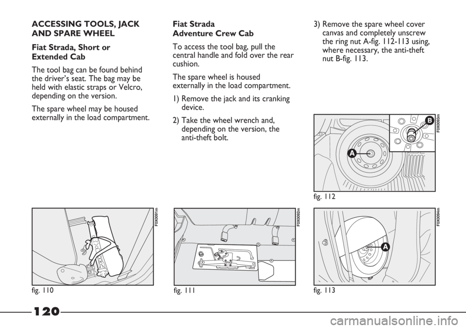
The tool bag can be found behind
the driver’s seat. The bag may be
held with elastic straps or Velcro,
depending on the version.
The spare wheel may be housed
externally in the load compartment.Fiat Strada
Adventure Crew Cab
To access the tool bag, pull the
central handle and fold over the rear
cushion.
The spare wheel is housed
externally in the load compartment.
1) Remove the jack and its cranking
device.
2) Take the wheel wrench and,
depending on the version, the
anti-theft bolt.3) Remove the spare wheel cover
canvas and completely unscrew
the ring nut A-fig. 112-113 using,
where necessary, the anti-theft
nut B-fig. 113.
fig. 113
F0X0094m
fig. 112
F0X0093m
fig. 110
F0X0091m
fig. 111
F0X0092m
Page 123 of 195
121
CHANGING THE WHEEL
1) Loosen the fixing bolts of the
wheel to be replaced by about
one turn.
2) With alloy wheels, shake the
vehicle to detach the rim from
the wheel hub more easily.
3) Turn the jack’s cranking device in
order to open it partially.
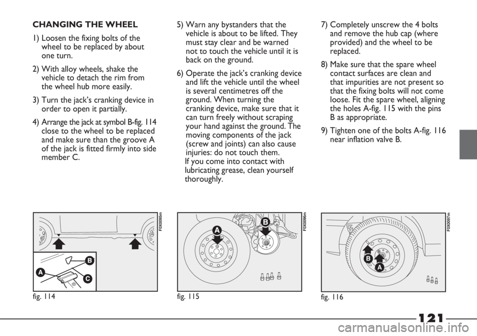
4) Arrange the jack at symbol B-fig. 114
close to the wheel to be replaced
and make sure than the groove A
of the jack is fitted firmly into side
member C.5) Warn any bystanders that the
vehicle is about to be lifted. They
must stay clear and be warned
not to touch the vehicle until it is
back on the ground.
6) Operate the jack’s cranking device
and lift the vehicle until the wheel
is several centimetres off the
ground. When turning the
cranking device, make sure that it
can turn freely without scraping
your hand against the ground. The
moving components of the jack
(screw and joints) can also cause
injuries: do not touch them.
If you come into contact with
lubricating grease, clean yourself
thoroughly.7) Completely unscrew the 4 bolts
and remove the hub cap (where
provided) and the wheel to be
replaced.
8) Make sure that the spare wheel
contact surfaces are clean and
that impurities are not present so
that the fixing bolts will not come
loose. Fit the spare wheel, aligning
the holes A-fig. 115 with the pins
B as appropriate.
9) Tighten one of the bolts A-fig. 116
near inflation valve B.
A
B
fig. 116
F0X0097m
fig. 114
F0X0095m
fig. 115
F0X0096m
Page 124 of 195
122
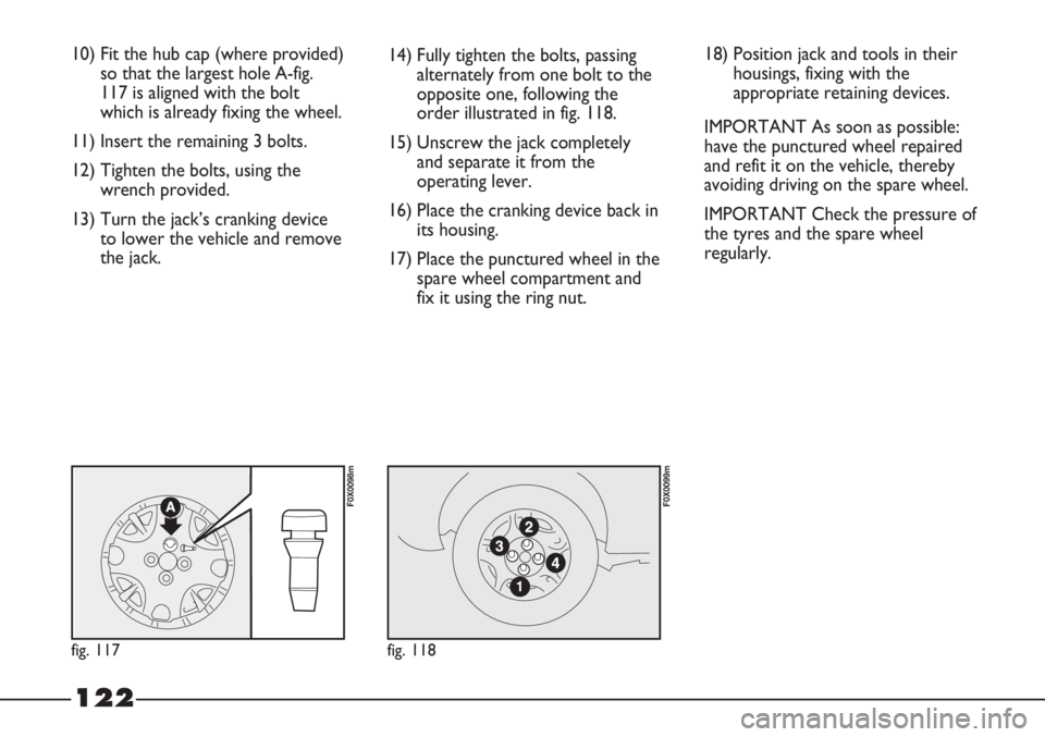
10) Fit the hub cap (where provided)
so that the largest hole A-fig.
117 is aligned with the bolt
which is already fixing the wheel.
11) Insert the remaining 3 bolts.
12) Tighten the bolts, using the
wrench provided.
13) Turn the jack’s cranking device
to lower the vehicle and remove
the jack.14) Fully tighten the bolts, passing
alternately from one bolt to the
opposite one, following the
order illustrated in fig. 118.
15) Unscrew the jack completely
and separate it from the
operating lever.
16) Place the cranking device back in
its housing.
17) Place the punctured wheel in the
spare wheel compartment and
fix it using the ring nut.
fig. 117
F0X0098m
fig. 118
F0X0099m
18) Position jack and tools in their
housings, fixing with the
appropriate retaining devices.
IMPORTANT As soon as possible:
have the punctured wheel repaired
and refit it on the vehicle, thereby
avoiding driving on the spare wheel.
IMPORTANT Check the pressure of
the tyres and the spare wheel
regularly.
Page 130 of 195
128
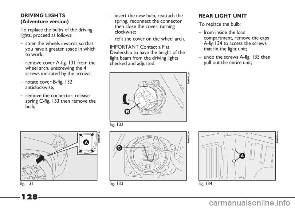
DRIVING LIGHTS
(Adventure version)
To replace the bulbs of the driving
lights, proceed as follows:
– steer the wheels inwards so that
you have a greater space in which
to work;
– remove cover A-fig. 131 from the
wheel arch, unscrewing the 4
screws indicated by the arrows;
– rotate cover B-fig. 132
anticlockwise;
– remove the connector, release
spring C-fig. 133 then remove the
bulb;
fig. 131
F0X0111m
fig. 132
F0X0112m
fig. 133
F0X0113m
fig. 134
F0X0114m
– insert the new bulb, reattach the
spring, reconnect the connector
then close the cover, turning
clockwise;
– refit the cover on the wheel arch.
IMPORTANT Contact a Fiat
Dealership to have the height of the
light beam from the driving lights
checked and adjusted.REAR LIGHT UNIT
To replace the bulb:
– from inside the load
compartment, remove the caps
A-fig.134 to access the screws
that fix the light unit;
– undo the screws A-fig. 135 then
pull out the entire unit;
Page 135 of 195
133
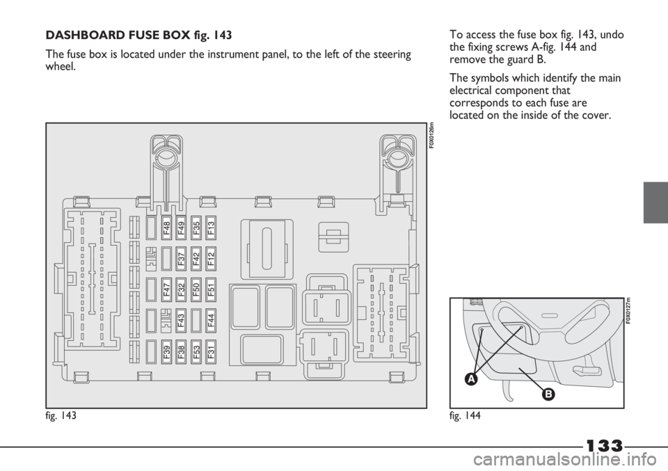
To access the fuse box fig. 143, undo
the fixing screws A-fig. 144 and
remove the guard B.
The symbols which identify the main
electrical component that
corresponds to each fuse are
located on the inside of the cover.
fig. 143
F0X0126m
fig. 144
F0X0127m
DASHBOARD FUSE BOX fig. 143
The fuse box is located under the instrument panel, to the left of the steering
wheel.