warning FIAT TALENTO 2017 Owner handbook (in English)
[x] Cancel search | Manufacturer: FIAT, Model Year: 2017, Model line: TALENTO, Model: FIAT TALENTO 2017Pages: 228, PDF Size: 4.47 MB
Page 135 of 228
149) 150)
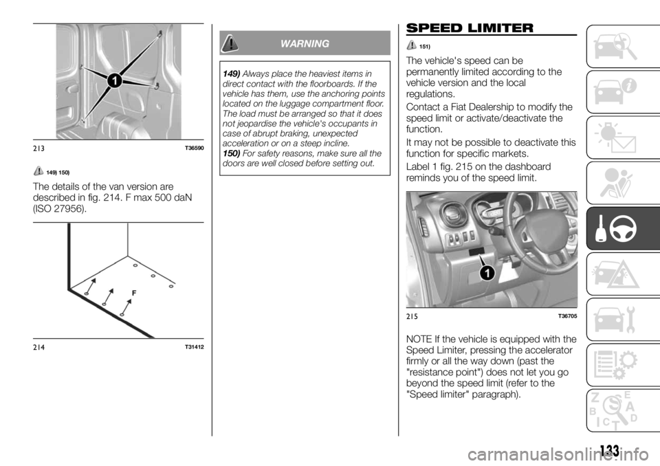
The details of the van version are
described in fig. 214. F max 500 daN
(ISO 27956).
WARNING
149)Always place the heaviest items in
direct contact with the floorboards. If the
vehicle has them, use the anchoring points
located on the luggage compartment floor.
The load must be arranged so that it does
not jeopardise the vehicle's occupants in
case of abrupt braking, unexpected
acceleration or on a steep incline.
150)For safety reasons, make sure all the
doors are well closed before setting out.
SPEED LIMITER
151)
The vehicle's speed can be
permanently limited according to the
vehicle version and the local
regulations.
Contact a Fiat Dealership to modify the
speed limit or activate/deactivate the
function.
It may not be possible to deactivate this
function for specific markets.
Label 1 fig. 215 on the dashboard
reminds you of the speed limit.
NOTE If the vehicle is equipped with the
Speed Limiter, pressing the accelerator
firmly or all the way down (past the
"resistance point") does not let you go
beyond the speed limit (refer to the
"Speed limiter" paragraph).
213T36590
214T31412
215T36705
133
Page 136 of 228
IMPORTANT In certain situations (for
example, a steep slope) the speed
limiter can be exceeded slightly,
because the device does not intervene
on the braking system.
WARNING
151)This function does not take the
driver's place. Nor does it allow the
vehicle's driving limits to be ignored,
encouraging faster driving. However, this
does not exempt the driver from normal
driving safety or from responsibility.
MINIMUM SPEED
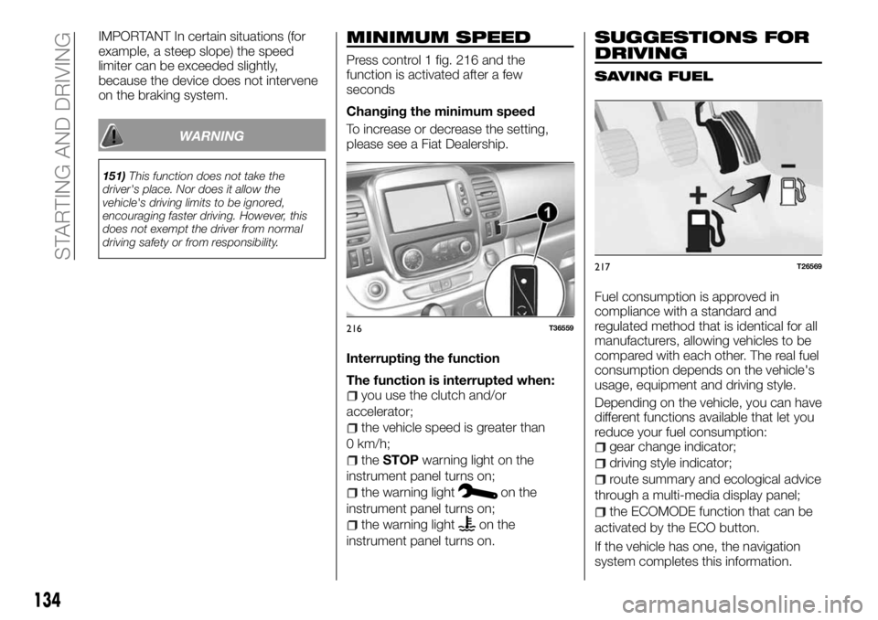
Press control 1 fig. 216 and the
function is activated after a few
seconds
Changing the minimum speed
To increase or decrease the setting,
please see a Fiat Dealership.
Interrupting the function
The function is interrupted when:
you use the clutch and/or
accelerator;
the vehicle speed is greater than
0 km/h;
theSTOPwarning light on the
instrument panel turns on;
the warning lighton the
instrument panel turns on;
the warning lighton the
instrument panel turns on.
SUGGESTIONS FOR
DRIVING
SAVING FUEL
Fuel consumption is approved in
compliance with a standard and
regulated method that is identical for all
manufacturers, allowing vehicles to be
compared with each other. The real fuel
consumption depends on the vehicle's
usage, equipment and driving style.
Depending on the vehicle, you can have
different functions available that let you
reduce your fuel consumption:
gear change indicator;
driving style indicator;
route summary and ecological advice
through a multi-media display panel;
the ECOMODE function that can be
activated by the ECO button.
If the vehicle has one, the navigation
system completes this information.
216T36559
217T26569
134
STARTING AND DRIVING
Page 137 of 228
Gear change indicators
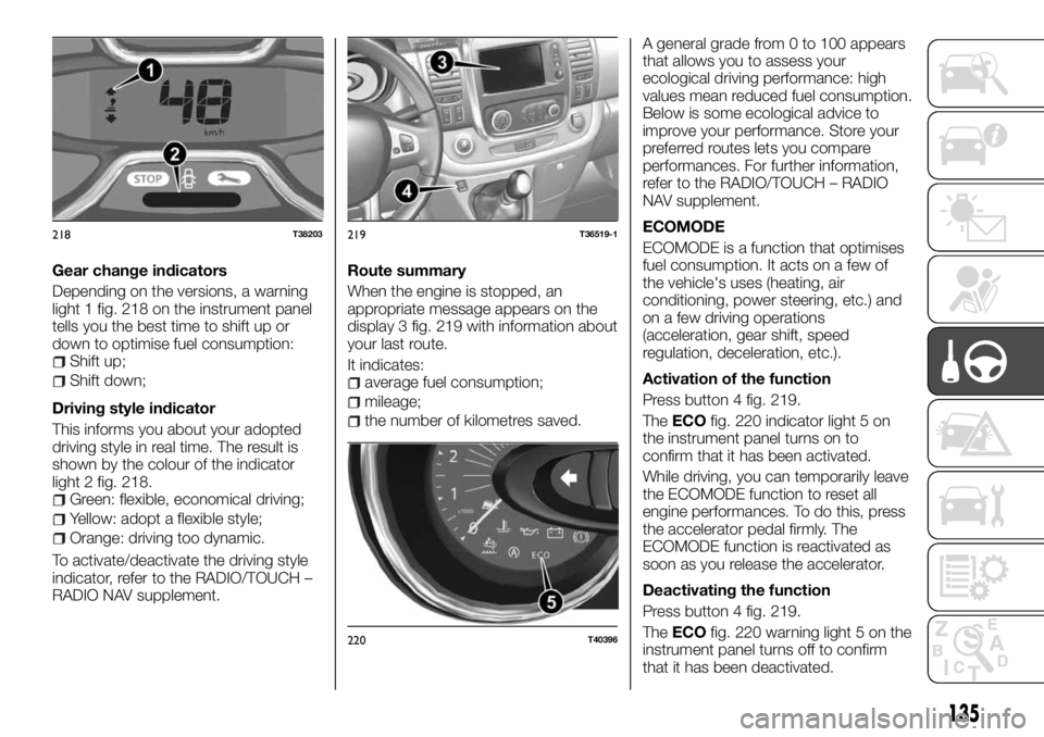
Depending on the versions, a warning
light 1 fig. 218 on the instrument panel
tells you the best time to shift up or
down to optimise fuel consumption:
Shift up;
Shift down;
Driving style indicator
This informs you about your adopted
driving style in real time. The result is
shown by the colour of the indicator
light 2 fig. 218.
Green: flexible, economical driving;
Yellow: adopt a flexible style;
Orange: driving too dynamic.
To activate/deactivate the driving style
indicator, refer to the RADIO/TOUCH –
RADIO NAV supplement.Route summary
When the engine is stopped, an
appropriate message appears on the
display 3 fig. 219 with information about
your last route.
It indicates:
average fuel consumption;
mileage;
the number of kilometres saved.A general grade from 0 to 100 appears
that allows you to assess your
ecological driving performance: high
values mean reduced fuel consumption.
Below is some ecological advice to
improve your performance. Store your
preferred routes lets you compare
performances. For further information,
refer to the RADIO/TOUCH – RADIO
NAV supplement.
ECOMODE
ECOMODE is a function that optimises
fuel consumption. It acts on a few of
the vehicle's uses (heating, air
conditioning, power steering, etc.) and
on a few driving operations
(acceleration, gear shift, speed
regulation, deceleration, etc.).
Activation of the function
Press button 4 fig. 219.
TheECOfig. 220 indicator light 5 on
the instrument panel turns on to
confirm that it has been activated.
While driving, you can temporarily leave
the ECOMODE function to reset all
engine performances. To do this, press
the accelerator pedal firmly. The
ECOMODE function is reactivated as
soon as you release the accelerator.
Deactivating the function
Press button 4 fig. 219.
TheECOfig. 220 warning light 5 on the
instrument panel turns off to confirm
that it has been deactivated.
218T38203219T36519-1
220T40396
135
Page 139 of 228
IN AN EMERGENCY
A punctured tyre or a burnt-out bulb?
At times, a problem may interfere with
our journey.
The pages on emergencies can help
you to deal with critical situations
independently and with calm.
In an emergency we recommend that
you call the toll free phone number
found in the Warranty Booklet.
It is also possible to call the national or
international universal freephone
number to search for the nearest Fiat
Dealership.HAZARD WARNING LIGHTS.....139
REPLACING AN INTERNAL BULB .139
REPLACING AN EXTERNAL BULB .140
PASSENGER COMPARTMENT
FUSES...................144
IN THE EVENT OF A PUNCTURE . .148
CHANGING A WHEEL.........148
TYRE INFLATION KIT..........151
JUMP STARTING............153
BATTERY RECHARGING.......154
TOWING THE VEHICLE........155
137
Page 140 of 228

HAZARD WARNING
LIGHTS
CONTROL
Press button 2 fig. 223. This
simultaneously activates the four
flashing arrows and those on the side. It
must be used only in case of danger to
warn other drivers that you have had to
stop in an unusual or prohibited place
or in special driving or traffic conditions.
Depending on the trim, in case you
stop abruptly, the emergency lights can
go on automatically. You can turn them
off by pressing the button 2
fig. 223 once.
REPLACING AN
INTERNAL BULB
152) 153) 154) 155)
Courtesy lights
Remove the lens from the courtesy light
concerned (1 fig. 224, 2 and 3 fig. 225,
6 and 7 fig. 226 ) using a screwdriver.
Pull the bulb downwards to remove
from its housing.
Type of bulb: W6W
Replace the bulb and reposition the
press-fit lens.
Vehicles with reading light
Type of bulb 2 fig. 227: pin type, 10W
Type of reading light bulb 3 fig. 227:
W5W
223T36520
224T36566
225T36567
226T36631
227T38811
138
IN AN EMERGENCY
Page 141 of 228
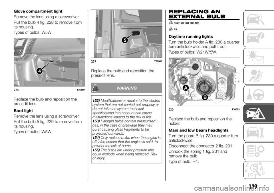
Glove compartment light
Remove the lens using a screwdriver.
Pull the bulb 4 fig. 228 to remove from
its housing.
Types of bulbs: W5W
Replace the bulb and reposition the
press-fit lens.
Boot light
Remove the lens using a screwdriver.
Pull the bulb 5 fig. 229 to remove from
its housing.
Types of bulbs: W5WReplace the bulb and reposition the
press-fit lens.
WARNING
152)Modifications or repairs to the electric
system that are not carried out properly or
do not take the system technical
specifications into account can cause
malfunctions leading to the risk of fire.
153)Halogen bulbs contain pressurised
gas, in the case of breakage they may
burst causing glass fragments to be
projected outwards.
154)Only replace bulbs when the engine is
off. Also ensure that the engine is cold, to
prevent the risk of burns.
155)The bulbs are under pressure and
could explode when being replaced. Risk
of injury.
REPLACING AN
EXTERNAL BULB
156) 157) 158) 159) 160)
29)
Daytime running lights
Turn the bulb holder A fig. 230 a quarter
turn anticlockwise and pull it out.
Types of bulbs: W21W/5W.
Replace the bulb and reposition the
holder.
Main and low beam headlights
Turn the guard B fig. 230 a quarter turn
anticlockwise.
Disconnect the connector 2 fig. 231.
Unhook the spring 1 fig. 231 and
remove the bulb.
Type of bulb: H4.
228T36569
229T36568
230T36663
139
Page 144 of 228
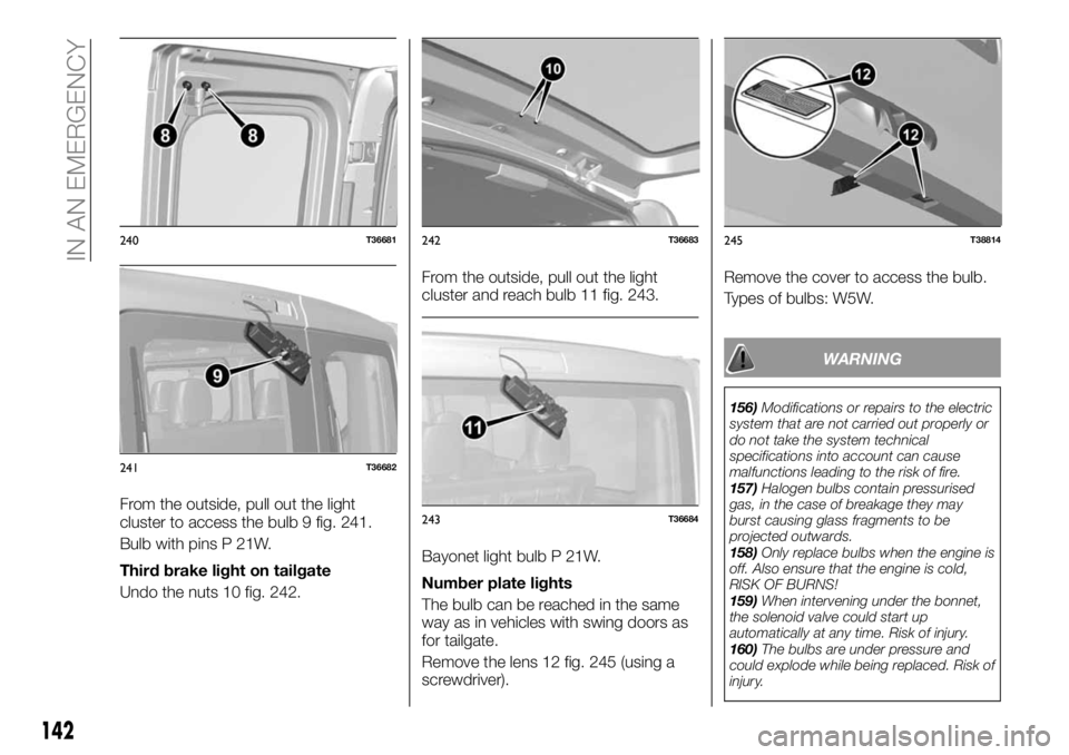
From the outside, pull out the light
cluster to access the bulb 9 fig. 241.
Bulb with pins P 21W.
Third brake light on tailgate
Undo the nuts 10 fig. 242.From the outside, pull out the light
cluster and reach bulb 11 fig. 243.
Bayonet light bulb P 21W.
Number plate lights
The bulb can be reached in the same
way as in vehicles with swing doors as
for tailgate.
Remove the lens 12 fig. 245 (using a
screwdriver).Remove the cover to access the bulb.
Types of bulbs: W5W.
WARNING
156)Modifications or repairs to the electric
system that are not carried out properly or
do not take the system technical
specifications into account can cause
malfunctions leading to the risk of fire.
157)Halogen bulbs contain pressurised
gas, in the case of breakage they may
burst causing glass fragments to be
projected outwards.
158)Only replace bulbs when the engine is
off. Also ensure that the engine is cold,
RISK OF BURNS!
159)When intervening under the bonnet,
the solenoid valve could start up
automatically at any time. Risk of injury.
160)The bulbs are under pressure and
could explode while being replaced. Risk of
injury.
240T36681
241T36682
242T36683
243T36684
245T38814
142
IN AN EMERGENCY
Page 147 of 228
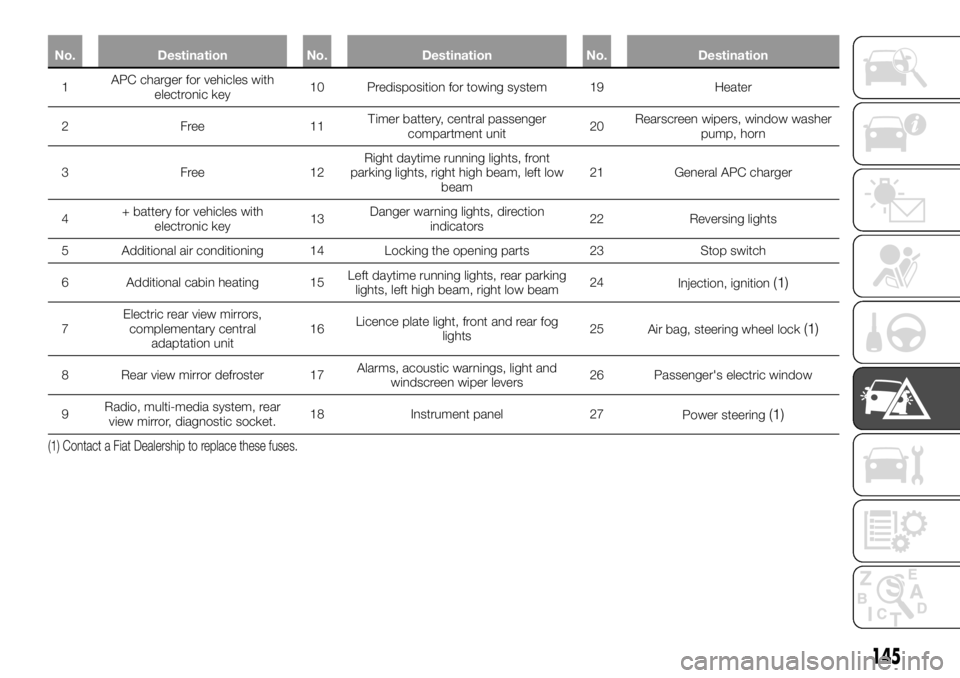
No. Destination No. Destination No. Destination
1APCcharger for vehicles with
electronic key10 Predisposition for towing system 19 Heater
2Free11Timer battery, central passenger
compartment unit20Rearscreen wipers, window washer
pump, horn
3Free12Right daytime running lights, front
parking lights, right high beam, left low
beam21 General APC charger
4+ battery for vehicles with
electronic key13Danger warning lights, direction
indicators22 Reversing lights
5 Additional air conditioning 14 Locking the opening parts 23 Stop switch
6 Additional cabin heating 15Left daytime running lights, rear parking
lights, left high beam, right low beam24
Injection, ignition
(1)
7Electric rear view mirrors,
complementary central
adaptation unit16Licence plate light, front and rear fog
lights25
Air bag, steering wheel lock(1)
8 Rear view mirror defroster 17Alarms, acoustic warnings, light and
windscreen wiper levers26 Passenger's electric window
9Radio, multi-media system, rear
view mirror, diagnostic socket.18 Instrument panel 27
Power steering
(1)
(1) Contact a Fiat Dealership to replace these fuses.
145
Page 148 of 228
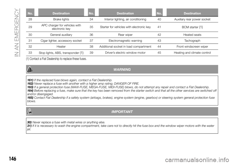
No. Destination No. Destination No. Destination
28 Brake lights 34 Interior lighting, air conditioning 40 Auxiliary rear power socket
29APCcharger for vehicles with
electronic key35 Starter for vehicles with electronic key 41
BCM starter
(1)
30 General auxiliary 36 Rear wiper 42 Heated seats
31 Cigar lighter, accessory socket 37 Electromagnetic warning 43 Tachograph
32 Heater 38 Additional socket in load compartment 44 Front windscreen wiper
33
Stop lights, ABS, transponder
(1)39 Driver’s electric window motor 45 Heating and climate control
(1) Contact a Fiat Dealership to replace these fuses.
WARNING
161)If the replaced fuse blows again, contact a Fiat Dealership.
162)Never replace a fuse with another with a higher amp rating; DANGER OF FIRE.
163)If a general protection fuse (MAXI-FUSE, MEGA-FUSE, MIDI-FUSE) blows, do not attempt any repair and contact a Fiat Dealership.
164)Before replacing a fuse, make sure that the key has been removed from the starter switch and that all the other services are switched off
and/or disengaged.
165)Contact Fiat Dealership if a safety system (airbags, brakes), engine system (engine, gearbox) or steering system general protection fuse
blows.
IMPORTANT
30)Never replace a fuse with metal wires or anything else.
31)If it is necessary to wash the engine compartment, take care not to directly hit the fuse box and the window wiper motors with the water
jet.
146
IN AN EMERGENCY
Page 151 of 228
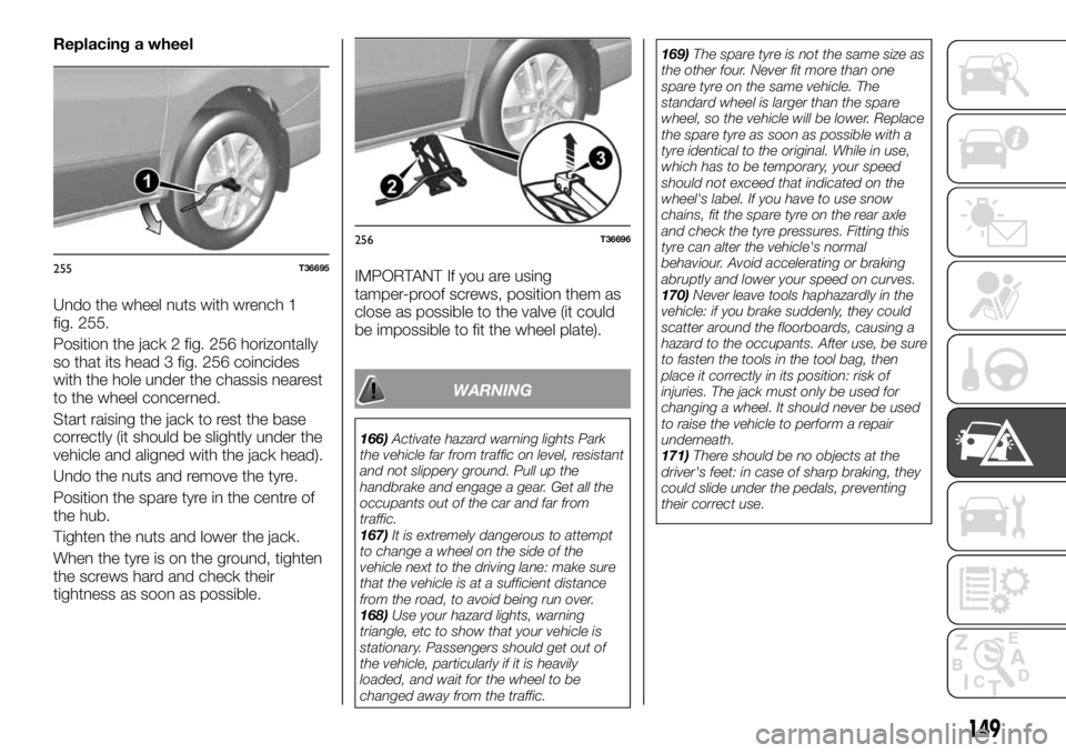
Replacing a wheel
Undo the wheel nuts with wrench 1
fig. 255.
Position the jack 2 fig. 256 horizontally
so that its head 3 fig. 256 coincides
with the hole under the chassis nearest
to the wheel concerned.
Start raising the jack to rest the base
correctly (it should be slightly under the
vehicle and aligned with the jack head).
Undo the nuts and remove the tyre.
Position the spare tyre in the centre of
the hub.
Tighten the nuts and lower the jack.
When the tyre is on the ground, tighten
the screws hard and check their
tightness as soon as possible.IMPORTANT If you are using
tamper-proof screws, position them as
close as possible to the valve (it could
be impossible to fit the wheel plate).
WARNING
166)Activate hazard warning lights Park
the vehicle far from traffic on level, resistant
and not slippery ground. Pull up the
handbrake and engage a gear. Get all the
occupants out of the car and far from
traffic.
167)It is extremely dangerous to attempt
to change a wheel on the side of the
vehicle next to the driving lane: make sure
that the vehicle is at a sufficient distance
from the road, to avoid being run over.
168)Use your hazard lights, warning
triangle, etc to show that your vehicle is
stationary. Passengers should get out of
the vehicle, particularly if it is heavily
loaded, and wait for the wheel to be
changed away from the traffic.169)The spare tyre is not the same size as
the other four. Never fit more than one
spare tyre on the same vehicle. The
standard wheel is larger than the spare
wheel, so the vehicle will be lower. Replace
the spare tyre as soon as possible with a
tyre identical to the original. While in use,
which has to be temporary, your speed
should not exceed that indicated on the
wheel's label. If you have to use snow
chains, fit the spare tyre on the rear axle
and check the tyre pressures. Fitting this
tyre can alter the vehicle's normal
behaviour. Avoid accelerating or braking
abruptly and lower your speed on curves.
170)Never leave tools haphazardly in the
vehicle: if you brake suddenly, they could
scatter around the floorboards, causing a
hazard to the occupants. After use, be sure
to fasten the tools in the tool bag, then
place it correctly in its position: risk of
injuries. The jack must only be used for
changing a wheel. It should never be used
to raise the vehicle to perform a repair
underneath.
171)There should be no objects at the
driver's feet: in case of sharp braking, they
could slide under the pedals, preventing
their correct use.
255T36695
256T36696
149