lock FIAT TALENTO 2020 Owner handbook (in English)
[x] Cancel search | Manufacturer: FIAT, Model Year: 2020, Model line: TALENTO, Model: FIAT TALENTO 2020Pages: 236, PDF Size: 4.86 MB
Page 104 of 236
FITTING A CHILD
RESTRAINT SYSTEM
WITH SEAT BELTS
135) 136)
The seat belt must be adjusted to
ensure it works in case of abrupt
braking or collision. Comply with the
belt direction indicated by the child
restraint system manufacturer.
Check that the seat belt is fastened
correctly.
Check that the child seat is correctly
locked in place by moving it left/right
and forwards/backwards: the seat
should remain firmly in place. Make sure
that the child restraint system is not
installed crosswise and is not resting
against a window.
102
SAFETY
Page 127 of 236
WARNING
127)To prevent opening the door from the inside, use the safety device (refer to the "Child safety” paragraph in the “Knowing your vehicle”
chapter).
128)A collision at 50 Km/h is the equivalent of falling 10 meters. Never hold a child in your arms or on your knees, in case of an accident you
would never be able to hold him even if you have your seat bets fastened. If the vehicle has been involved in a road accident, replace the child
restraint system, and check the seat belts and ISOFIX anchorages.
129)Never leave the vehicle unguarded with the electronic key and a child, a handicapped person or an animal inside, even for a short time.
This could result in your own safety or that of others who could start the engine, setting in motion equipment such as the electric windows or
even locking the doors. Moreover, in hot and/or sunny weather, the vehicle's interior temperature will increase rapidly. Risk of death or serious
injury.
130)Never leave a child alone in the vehicle. Make sure the child always has his/her seat belt fastened and correctly adjusted. Avoid too
heavy clothing that causes the belts to be loose. Never allow the child to put his/her head or arm out the window. Make sure the child is
seated correctly throughout the trip. especially when asleep.
131)Make sure the child seat or his/her feet do not prevent the front seat from locking into place correctly. Refer to the "Front seat"
paragraph in the "Knowing your vehicle” chapter. Make sure that the child seat installed in the vehicle is not at risk of coming out of its
housing. If you have to remove the head rest, make sure it is positioned so it is not thrown about in case of abrupt braking or collision. Always
fasten the child seat even if you are not using it so it is not thrown about in case of abrupt braking or collision.
132)RISK OF DEATH OR SERIOUS INJURY: before installing a rear-facing child restraint system in the front passenger seat, check that the
air bag has been correctly deactivated (refer to the "Passenger side airbag and child restraint systems" paragraph in this chapter).
133)Install the child seat preferably in one of the rear seats.
134)Never install a child seat on the rear centre seat. RISK OF DEATH OR SERIOUS INJURY.
135)Do not use child seats that could unlock the belt holding it in place: the child seat base must not rest on the seat belt buckle and/or
housing.
136)The seat belt must never be loose or twisted. Never pass the shoulder belt under your arm or behind your back. Check that the belt has
not been damaged by sharp edges. If the seat belt is not working normally, it will not protect the child. Contact a Fiat Dealership. Do not use
this seat until the belt has been repaired.
137)Using a child seat inappropriate for this vehicle will not properly protect the child. You risk causing him/her serious injury or death.
138)Do not modify any of the elements of the original safety system: seat belts, ISOFIX, seats and related fastening.
139)Check that the backrest of the forward-facing child restraint system is touching the backrest of the vehicle seat. In that case, the child
restraint system may not rest on the vehicle seat cushion.
140)The ISOFIX anchorages have been designed exclusively for child restraint systems with the ISOFIX system. Never fasten other child
restraint systems, nor seat belts or other objects to these anchorages. Check that there are no obstacles at the level of the anchor points. If
the vehicle has been involved in a road accident, have the ISOFIX anchorages checked and replace the child restraint system.
141)Never install a child restraint system with support feet on the central rear seat. Risk of death or serious injury.
125
Page 128 of 236
ACTIVE SAFETY
SYSTEMS
Depending on the version, they can
consist of:
by the anti-lock braking system
(ABS);
electronic stability control (ESC) with
understeering and traction control
system;
driving with a trailer assistance;
emergency brake assistance;
road grip control;
assisted departure on inclines.
ABS (Anti-lock Braking
System)
142) 143) 144) 145)
In case of sharp braking, the ABS
avoids wheel locking, so it manages the
braking distance and maintains vehicle
control.
In these conditions you can carry out
manoeuvres while braking fully.
Moreover, this system optimises the
braking distance, especially on slippery
surfaces (wet roadbed, etc.).
Every time you activate this device, you
know because the brake pedal shakes.
The ABS never improves the "physical"
performance associated with grip
between the wheel and the road. The
rules of the road must be respected
(safety distance between vehicles, etc.).IMPORTANT In an emergency, we
advise you to apply strong, continuous
pressure to the brake pedal. You do not
need to pump it. The ABS will modulate
the force applied to the brakes.
Irregular operation:
andlit on the instrument
panel accompanied by the dedicated
message on the display indicate
deactivation of the ABS, of the ESC
and of the emergency servo brake.
Braking is always guaranteed;
andSTOPlit on the
instrument panel, along with the
dedicated message on the display,
indicates that there is a fault in the
brake system.
In both cases, contact a Fiat
Dealership.
ESC (Electronic Stability
Control) SYSTEM
146) 147)
Electronic stability control ESC
This system helps maintain control of
the vehicle in "critical" driving conditions
(avoiding an obstacle, loss of grip in a
curve, etc.).
Operating principle
A sensor on the steering wheel
recognises the driving trajectory that the
driver set.
Other sensors installed in the vehicle
measure the real trajectory.The system compares the driver's
adherence to the effective trajectory,
correcting it if necessary, braking a few
wheels and/or reducing engine power if
the system was activated and its
warning light
flashes on the
instrument panel.
Understeering control
This system optimises the ESC action
in case of noticeable understeer (loss of
front grip).
Traction Control System
This system limits the drive wheels
slipping and helps control the vehicle
when starting out, accelerating or
decelerating.
Operating principle
Thanks to the sensor in the wheels, the
system measures and compares the
drive wheel rotation speed, detecting
immediately loss of grip. If a wheel
starts sliding, the system intervenes by
braking to re-stabilise the drive that is
compatible with the level of road grip.
The system also acts on the engine
speed, adapting it to wheel road grip,
independently of the driver's use of the
accelerator.
Irregular operation
When the system detects an
operational irregularity, the dedicated
message appears on the display and
the warning lights
andturn
on.
126
SAFETY
Page 135 of 236
RemarksIf the vehicle does not start, a
dedicated message appears on the
instrument panel;
In some cases, you will need to
move the steering wheel while pressing
the ignition button 1 to unlock the
steering wheel column; You will be
warned with message to this effect;
When starting the engine in very cold
weather (less than -10°C): keep the
clutch pressed until the engine starts.
Accessory function
When the engine starts, you can
access a few functions (radio,
navigation system, windscreen wipers,
etc.).
To make the other functions available,
with the key in the passenger
compartment or inserted in the key
reader 2 fig. 211, press button
1 without pressing on the pedals.
Irregular operation
The electronic key with easy access will
not function in the following instances:
The electronic key might have dead
batteries
In the vicinity of a device functioning
on the same frequency (screen cell
phone, video games, etc.);
The vehicle is located in an area
known for a high presence of
electro-magnetic waves.A message to this effect appears in the
instrument panel.
Insert the electronic key in the reader 2
fig. 211 as far as it will go.
STOPPING THE ENGINE
153) 154)
24) 25)
Vehicles with an electronic key
The vehicle needs to be stopped.
With the electronic key in the reader 2
fig. 211 or in the detection area 3
fig. 212, press button 1 fig. 211: the
engine turns off. The steering wheel
lock locks when the driver's door opens
or when the vehicle is locked.
If the key is not in the passenger
compartment when you try to turn the
engine off, a dedicated message
appears on the instrument panel: press
button 1 fig. 211 for more than
2 seconds.
After turning the engine off, a few
accessories still on (radio, etc.) continue
functioning for about 10 minutes.
When you open the driver's door, the
accessories turn off.
WARNING
149)Do not start the vehicle on an incline
with the gear in neutral. The power steering
might not activate. Risk of accident.150)It is dangerous to run the engine in
enclosed areas. The engine takes in
oxygen and releases carbon dioxide,
carbon monoxide and other toxic gases.
151)The brake servo is not active until the
engine is started, so you would need to
apply much more force than usual to the
brake pedal.
152)Do not start the engine by pushing,
towing or driving downhill. These
manoeuvres may damage the catalytic
converter.
153)Do not remove the key from the
starter device or the electronic key from the
reader before effectively stopping the
vehicle; stopping the engine means
deleting various aids: When the engine is
stopped, the power brakes, power steering
and safety devices like the air bags and
pre-tensioners no longer work.
154)Especially when you leave the car
with the electronic key in your pocket,
make sure the engine is effectively
stopped.
IMPORTANT
24)When the engine is stopped, never
leave the ignition device in the "M" position
to prevent useless current absorption from
draining the battery.
25)A quick burst on the accelerator before
turning off the engine serves absolutely no
practical purpose; it wastes fuel and is
especially damaging to turbocharged
engines.
133
Page 136 of 236
USING THE
GEARBOX
155)
26)
To engage reverse (vehicle
stopped)
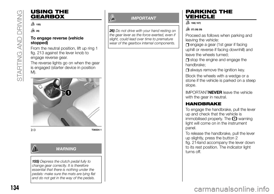
From the neutral position, lift up ring 1
fig. 213 against the lever knob to
engage reverse gear.
The reverse lights go on when the gear
is engaged (starter device in position
M).
WARNING
155)Depress the clutch pedal fully to
change gear correctly. It is therefore
essential that there is nothing under the
pedals: make sure the mats are lying flat
and do not get in the way of the pedals.
IMPORTANT
26)Do not drive with your hand resting on
the gear lever as the force exerted, even if
slight, could lead over time to premature
wear of the gearbox internal components.
PARKING THE
VEHICLE
156) 157)
27) 28) 29)
Proceed as follows when parking and
leaving the vehicle:
engage a gear (1st gear if facing
uphill or reverse if facing downhill) and
leave the wheels turned;
stop the engine and engage the
handbrake;
always remove the ignition key.
Block the wheels with a wedge or a
stone if the vehicle is parked on a steep
slope.
IMPORTANTNEVERleave the vehicle
with the gear in neutral.
HANDBRAKE
To engage the handbrake, pull the lever
up and check that the vehicle is
immobilised properly. The
warning
light will come on in the instrument
panel.
To release the handbrake, pull the lever
up slightly, press the button 2
fig. 214and accompany the lever down
to its rest position. The indicator light
turns off.
213T36534-1
134
STARTING AND DRIVING
Page 147 of 236
REPLACING AN
EXTERNAL BULB
167) 168) 169) 170) 171)
30)
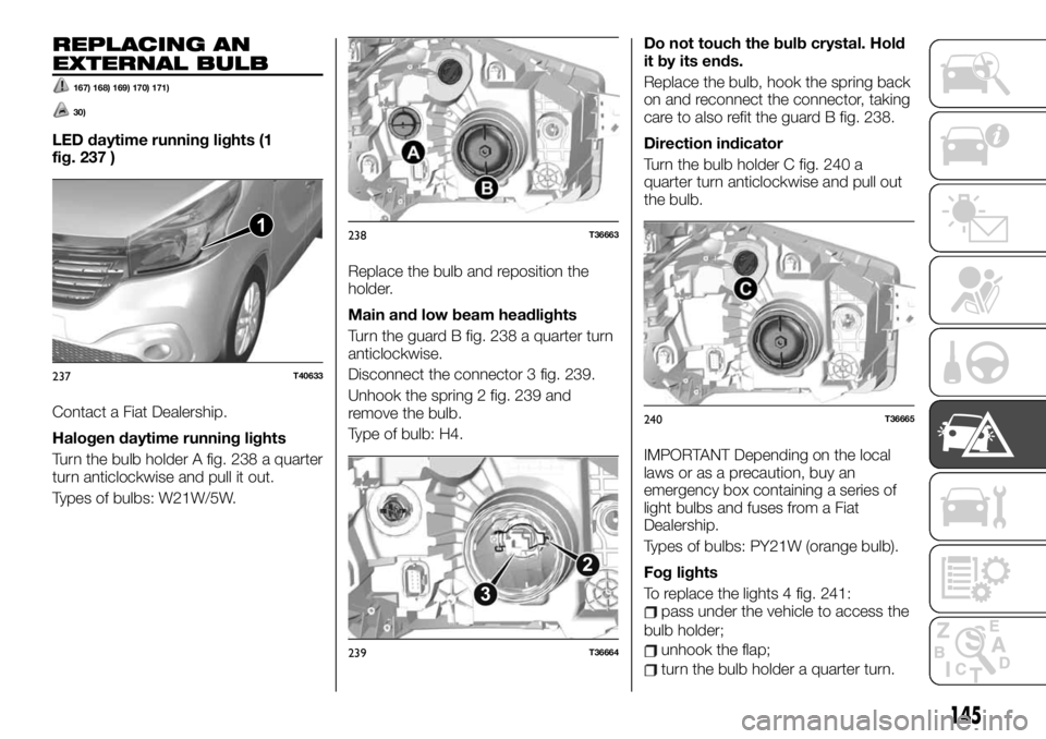
LED daytime running lights (1
fig. 237 )
Contact a Fiat Dealership.
Halogen daytime running lights
Turn the bulb holder A fig. 238 a quarter
turn anticlockwise and pull it out.
Types of bulbs: W21W/5W.Replace the bulb and reposition the
holder.
Main and low beam headlights
Turn the guard B fig. 238 a quarter turn
anticlockwise.
Disconnect the connector 3 fig. 239.
Unhook the spring 2 fig. 239 and
remove the bulb.
Type of bulb: H4.Do not touch the bulb crystal. Hold
it by its ends.
Replace the bulb, hook the spring back
on and reconnect the connector, taking
care to also refit the guard B fig. 238.
Direction indicator
Turn the bulb holder C fig. 240 a
quarter turn anticlockwise and pull out
the bulb.
IMPORTANT Depending on the local
laws or as a precaution, buy an
emergency box containing a series of
light bulbs and fuses from a Fiat
Dealership.
Types of bulbs: PY21W (orange bulb).
Fog lights
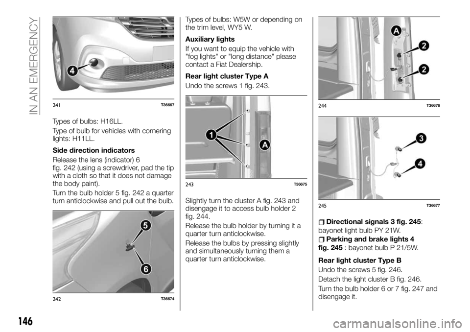
To replace the lights 4 fig. 241:
pass under the vehicle to access the
bulb holder;
unhook the flap;
turn the bulb holder a quarter turn.
1
237T40633
238T36663
2
3
239T36664
240T36665
145
Page 148 of 236
Types of bulbs: H16LL.
Type of bulb for vehicles with cornering
lights: H11LL.
Side direction indicators
Release the lens (indicator) 6
fig. 242 (using a screwdriver, pad the tip
with a cloth so that it does not damage
the body paint).
Turn the bulb holder 5 fig. 242 a quarter
turn anticlockwise and pull out the bulb.Types of bulbs: W5W or depending on
the trim level, WY5 W.
Auxiliary lights
If you want to equip the vehicle with
"fog lights" or "long distance" please
contact a Fiat Dealership.
Rear light cluster Type A
Undo the screws 1 fig. 243.
Slightly turn the cluster A fig. 243 and
disengage it to access bulb holder 2
fig. 244.
Release the bulb holder by turning it a
quarter turn anticlockwise.
Release the bulbs by pressing slightly
and simultaneously turning them a
quarter turn anticlockwise.
Directional signals 3 fig. 245:
bayonet light bulb PY 21W.
Parking and brake lights 4
fig. 245: bayonet bulb P 21/5W.
Rear light cluster Type B
Undo the screws 5 fig. 246.
Detach the light cluster B fig. 246.
Turn the bulb holder 6 or 7 fig. 247 and
disengage it.
4
241T36667
5
6
242T36674
243T36675
244T36676
245T36677
146
IN AN EMERGENCY
Page 153 of 236
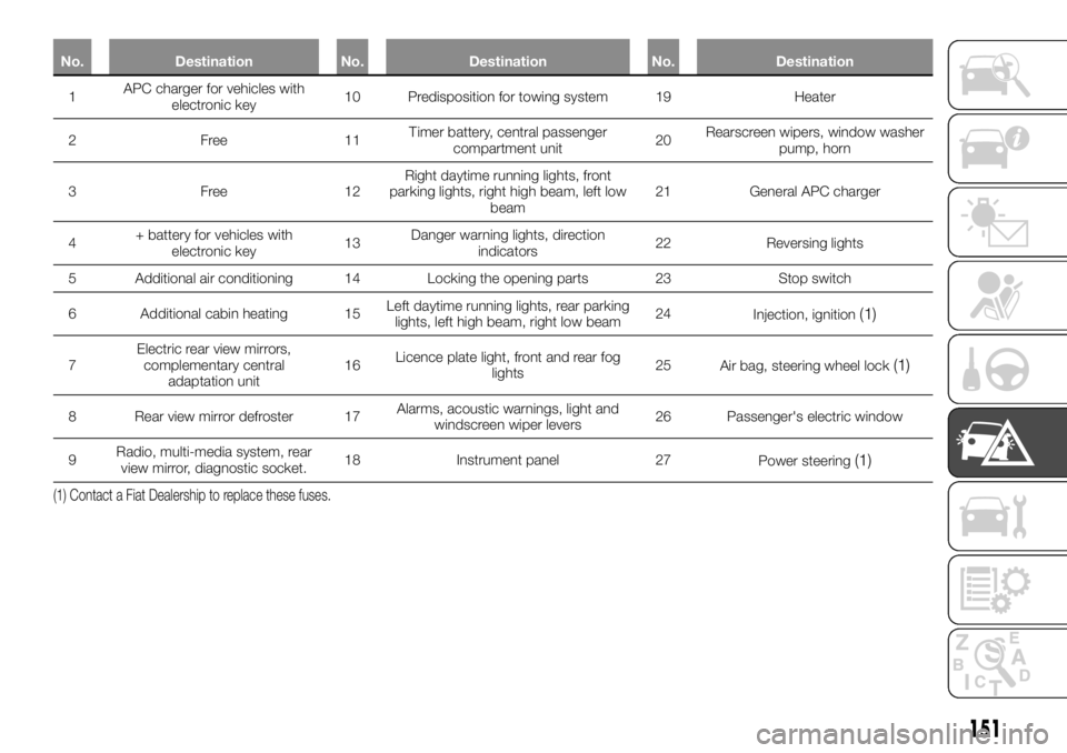
No. Destination No. Destination No. Destination
1APC charger forvehicles with
electronic key10 Predisposition for towing system 19 Heater
2Free11Timer battery, central passenger
compartment unit20Rearscreen wipers, window washer
pump, horn
3Free12Right daytime running lights, front
parking lights, right high beam, left low
beam21 General APC charger
4+ battery for vehicles with
electronic key13Danger warning lights, direction
indicators22 Reversing lights
5 Additional air conditioning 14 Locking the opening parts 23 Stop switch
6 Additional cabin heating 15Left daytime running lights, rear parking
lights, left high beam, right low beam24
Injection, ignition
(1)
7Electric rear view mirrors,
complementary central
adaptation unit16Licence plate light, front and rear fog
lights25
Air bag, steering wheel lock(1)
8 Rear view mirror defroster 17Alarms, acoustic warnings, light and
windscreen wiper levers26 Passenger's electric window
9Radio, multi-media system, rear
view mirror, diagnostic socket.18 Instrument panel 27
Power steering
(1)
(1) Contact a Fiat Dealership to replace these fuses.
151
Page 162 of 236
TOWING THE
VEHICLE
196) 197) 198)
41) 42) 43)
The steering wheel should not be
locked; the starter device has to be in
position "M" (ignition) to allow signalling
("Stop" lights, emergency lights). At
night the outside vehicle lighting must
remain on.
Detach the trailer where there is one.
Moreover, you have to comply with the
towing conditions, defined by the
regulations in force in the country you
are in.
Contact a Fiat Dealership.
Never use the gear or drive shafts to
tow the vehicle.
Use the rings exclusively for towing; in
no case must they be used to lift the
vehicle up, directly or indirectly.
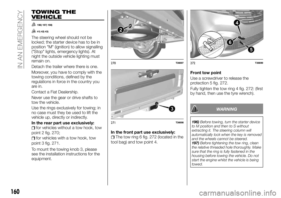
In the rear part use exclusively:
for vehicles without a tow hook, tow
point 2 fig. 270;
for vehicles with a tow hook, tow
point 3 fig. 271.
To mount the towing knob 3, please
see the installation instructions for the
equipment.In the front part use exclusively:The tow ring 6 fig. 272 (located in the
tool bag) and tow point 4.Front tow point
Use a screwdriver to release the
protection 5 fig. 272.
Fully tighten the tow ring 4 fig. 272: (first
by hand, then use the tyre wrench).
WARNING
196)Before towing, turn the starter device
to M position and then to S without
extracting it. The steering column will
automatically lock when the key is removed
and the wheels cannot be steered.
197)Before tightening the tow ring, clean
the relative threaded hole thoroughly. Make
sure that the ring is fully fastened in the
housing before towing the vehicle. Do not
start the engine whilst the vehicle is being
towed.
270T36697
271T36698
272T36699
160
IN AN EMERGENCY
Page 167 of 236
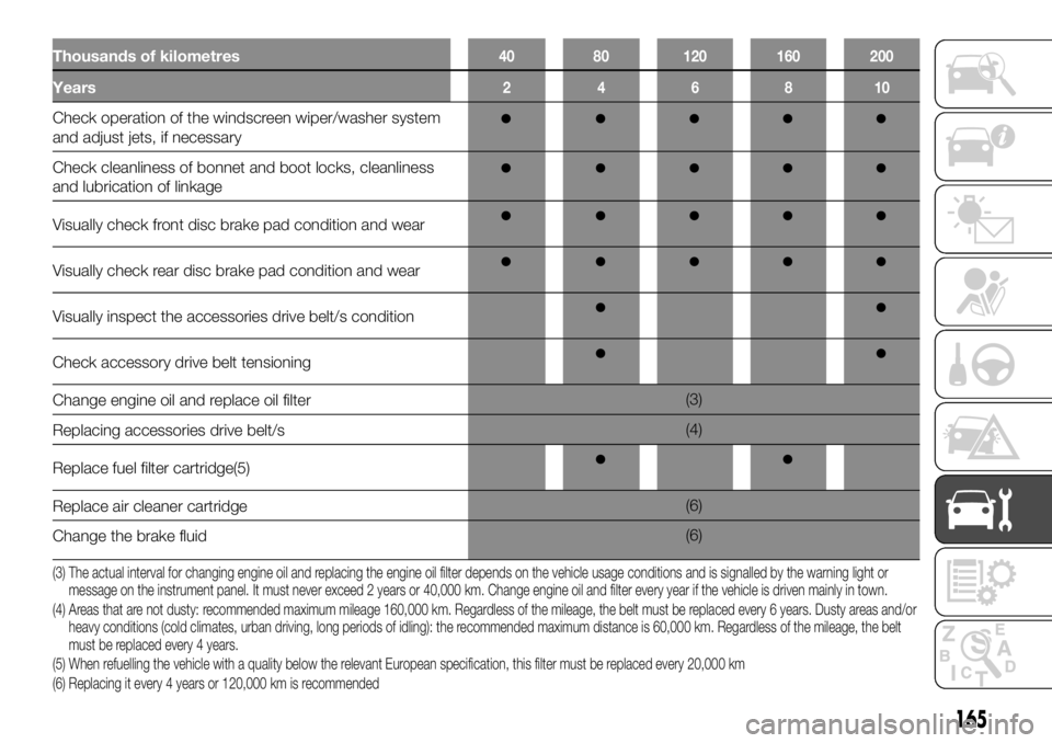
Thousands of kilometres40 80 120 160 200
Years246810
Check operation of the windscreen wiper/washer system
and adjust jets, if necessary
Check cleanliness of bonnet and boot locks, cleanliness
and lubrication of linkage
Visually check front disc brake pad condition and wear
Visually check rear disc brake pad condition and wear
Visually inspect the accessories drive belt/s condition
Check accessory drive belt tensioning
Change engine oil and replace oil filter(3)
Replacing accessories drive belt/s(4)
Replace fuel filter cartridge(5)
Replace air cleaner cartridge(6)
Change the brake fluid(6)
(3) The actual interval for changing engine oil and replacing the engine oil filter depends on the vehicle usage conditions and is signalled by the warning light or
message on the instrument panel. It must never exceed 2 years or 40,000 km. Change engine oil and filter every year if the vehicle is driven mainly in town.
(4) Areas that are not dusty: recommended maximum mileage 160,000 km. Regardless of the mileage, the belt must be replaced every 6 years. Dusty areas and/or
heavy conditions (cold climates, urban driving, long periods of idling): the recommended maximum distance is 60,000 km. Regardless of the mileage, the belt
must be replaced every 4 years.
(5) When refuelling the vehicle with a quality below the relevant European specification, this filter must be replaced every 20,000 km
(6) Replacing it every 4 years or 120,000 km is recommended
165