roof FIAT TALENTO 2020 Owner handbook (in English)
[x] Cancel search | Manufacturer: FIAT, Model Year: 2020, Model line: TALENTO, Model: FIAT TALENTO 2020Pages: 236, PDF Size: 4.86 MB
Page 2 of 236

We really know your vehicle because we invented,
designed and built it: we really know every single detail. At Fiat Professional Service authorised workshops you can find technicians directly trained by us, offering quality and pr\
ofessionalism for all service operations.
Fiat Professional workshops are always close to you for the regular serv\
icing operations, season checks and practical recommendations by our experts.
With Fiat Professional Genuine Parts you keep the reliability, comfort a\
nd performance features of your new vehicle unchanged in time: that's why you bought it for.
Always ask for Genuine Parts for the components used on our vehicles; we\
recommend them because they come from our steady commitment in research and development of highly innovative t\
echnologies. For all these reasons: rely on Genuine Parts,
because they are the only ones designed by Fiat Professional for your ve\
hicle.
WHY CHOOSING GENUINE PARTS
SAFETY: BRAKING
SYSTEMENVIRONMENT: PARTICULATE FILTERS,
CLIMATE CONTROL SYSTEM MAINTENANCECOMFORT:
SUSPENSION AND WINDSCREEN WIPERSPERFORMANCE:
SPARK PLUGS, INJECTORS AND BATTERIESLINEACCESSORI:
ROOF RACK BARS, WHEEL RIMS
COP TALENTO LUM GB.qxp 29/04/16 12:11 Pagina 2
Page 7 of 236
VEHICLE MODIFICATIONS / ALTERATIONS
WARNING
Any modification or alteration of the vehicle might seriously affect its safety and road holding, thus causing accidents, in which
the occupants could even be fatally injured.
ACCESSORIES PURCHASED BY THE OWNER
If after buying the vehicle, you decide to install electrical accessories that require a permanent electrical supply (e.g. radio,
satellite anti-theft system, etc.) or accessories that in any case burden the electrical supply, contact a Fiat Dealership, whose
personnel will check whether the vehicle's electrical system is able to withstand the load required, or whether it needs to be
integrated with a more powerful battery.
IMPORTANT Take care when fitting additional spoilers, alloy wheel rims or non-standard wheel hubs: they could reduce the
ventilation of the brakes and affect efficiency under sharp, repeated braking or on long descents. Make sure that nothing
obstructs the pedal stroke (mats, etc.).
INSTALLING ELECTRICAL/ELECTRONIC DEVICES
Electrical and electronic devices installed after buying the vehicle and available as after-sales must carry the following label:.
Fiat authorises the installation of transceivers provided that installation is carried out at a specialised centre, in a workmanlike
fashion and in compliance with manufacturer's specifications.
IMPORTANT Traffic authorities may not allow the vehicle on the road if devices are fitted that involve modifications to the
features of the vehicle. This may also cause lapse of the warranty in relation to faults caused by the change or either directly or
indirectly related to it.
Fiat shall not be liable for damage caused by the installation of accessories either not supplied or recommended by Fiat and/or
not installed in compliance with the provided instructions.
RADIO TRANSMITTERS AND MOBILE PHONES
Radio transmitter equipment (vehicle mobile phones, CB radios, amateur radio, etc.) cannot be used inside the car unless a
separate aerial is mounted on the roof of the vehicle.
Transmission and reception of these devices may be affected by the shielding effect of the vehicle body. As far as the use of
EC-approved mobile phones is concerned (GSM, GPRS, UMTS, LTE), follow the usage instructions provided by the mobile
phone Manufacturer.
IMPORTANT The use of such devices inside the passenger compartment (without an external aerial) may, in addition to
potential damage to the health of the passengers, cause malfunctions in the vehicle’s electronic systems, compromising the
safety of the vehicle.
5
Page 38 of 236
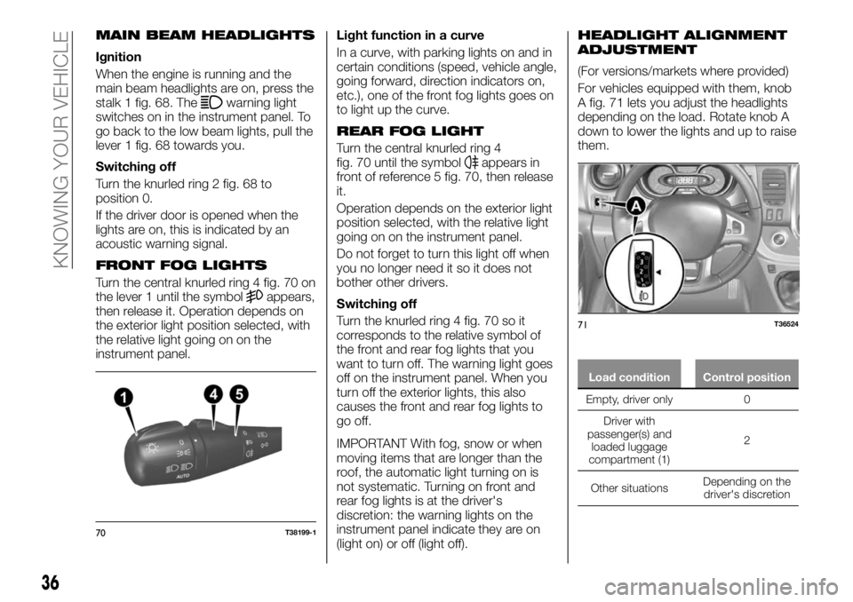
MAIN BEAM HEADLIGHTS
Ignition
When the engine is running and the
main beam headlights are on, press the
stalk 1 fig. 68. The
warning light
switches on in the instrument panel. To
go back to the low beam lights, pull the
lever 1 fig. 68 towards you.
Switching off
Turn the knurled ring 2 fig. 68 to
position 0.
If the driver door is opened when the
lights are on, this is indicated by an
acoustic warning signal.
FRONT FOG LIGHTS
Turn the central knurled ring 4 fig. 70 on
the lever 1 until the symbolappears,
then release it. Operation depends on
the exterior light position selected, with
the relative light going on on the
instrument panel.Light function in a curve
In a curve, with parking lights on and in
certain conditions (speed, vehicle angle,
going forward, direction indicators on,
etc.), one of the front fog lights goes on
to light up the curve.
REAR FOG LIGHT
Turn the central knurled ring 4
fig. 70 until the symbolappears in
front of reference 5 fig. 70, then release
it.
Operation depends on the exterior light
position selected, with the relative light
going on on the instrument panel.
Do not forget to turn this light off when
you no longer need it so it does not
bother other drivers.
Switching off
Turn the knurled ring 4 fig. 70 so it
corresponds to the relative symbol of
the front and rear fog lights that you
want to turn off. The warning light goes
off on the instrument panel. When you
turn off the exterior lights, this also
causes the front and rear fog lights to
go off.
IMPORTANT With fog, snow or when
moving items that are longer than the
roof, the automatic light turning on is
not systematic. Turning on front and
rear fog lights is at the driver's
discretion: the warning lights on the
instrument panel indicate they are on
(light on) or off (light off).
HEADLIGHT ALIGNMENT
ADJUSTMENT
(For versions/markets where provided)
For vehicles equipped with them, knob
A fig. 71 lets you adjust the headlights
depending on the load. Rotate knob A
down to lower the lights and up to raise
them.
Load condition Control position
Empty, driver only 0
Driver with
passenger(s) and
loaded
luggage
compartment (1)2
Other situationsDepending on the
driver's discretion
70T38199-1
71T36524
36
KNOWING YOUR VEHICLE
Page 70 of 236
MULTIMEDIA
EQUIPMENT
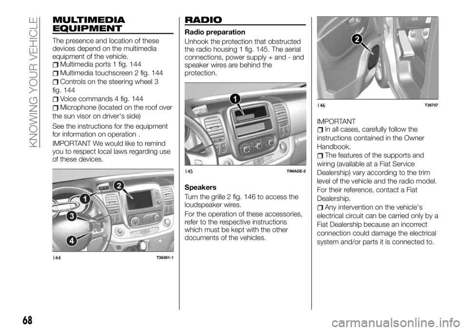
The presence and location of these
devices depend on the multimedia
equipment of the vehicle.
Multimedia ports 1 fig. 144
Multimedia touchscreen 2 fig. 144
Controls on the steering wheel 3
fig. 144
Voice commands 4 fig. 144
Microphone (located on the roof over
the sun visor on driver's side)
See the instructions for the equipment
for information on operation .
IMPORTANT We would like to remind
you to respect local laws regarding use
of these devices.
RADIO
Radio preparation
Unhook the protection that obstructed
the radio housing 1 fig. 145. The aerial
connections, power supply + and - and
speaker wires are behind the
protection.
Speakers
Turn the grille 2 fig. 146 to access the
loudspeaker wires.
For the operation of these accessories,
refer to the respective instructions
which must be kept with the other
documents of the vehicles.IMPORTANT
In all cases, carefully follow the
instructions contained in the Owner
Handbook.
The features of the supports and
wiring (available at a Fiat Service
Dealership) vary according to the trim
level of the vehicle and the radio model.
For their reference, contact a Fiat
Dealership.
Any intervention on the vehicle's
electrical circuit can be carried only by a
Fiat Dealership because an incorrect
connection could damage the electrical
system and/or parts it is connected to.
144T36591-1
145TIMAGE-2
146T36707
68
KNOWING YOUR VEHICLE
Page 143 of 236
Some advice for reducing fuel
consumption and thus helping
safeguard the environment:
If the vehicle has been parked in high
temperatures or in the sun, open up the
doors to let out the hot air before
leaving.
Do not leave the roof rack mounted if
not in use.
When transporting particularly large
objects, use a trailer if possible.
To tow a camper, use an approved
deflector and do not forget to adjust it.
Avoid "door to door" use of the
vehicle (short trips with prolonged
stops) because the engine never
reaches its ideal temperature.
141
Page 157 of 236
Replacing a wheel
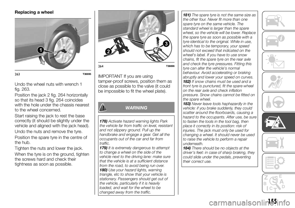
Undo the wheel nuts with wrench 1
fig. 263.
Position the jack 2 fig. 264 horizontally
so that its head 3 fig. 264 coincides
with the hole under the chassis nearest
to the wheel concerned.
Start raising the jack to rest the base
correctly (it should be slightly under the
vehicle and aligned with the jack head).
Undo the nuts and remove the tyre.
Position the spare tyre in the centre of
the hub.
Tighten the nuts and lower the jack.
When the tyre is on the ground, tighten
the screws hard and check their
tightness as soon as possible.IMPORTANT If you are using
tamper-proof screws, position them as
close as possible to the valve (it could
be impossible to fit the wheel plate).
WARNING
178)Activate hazard warning lights Park
the vehicle far from traffic on level, resistant
and not slippery ground. Pull up the
handbrake and engage a gear. Get all the
occupants out of the car and far from
traffic.
179)It is extremely dangerous to attempt
to change a wheel on the side of the
vehicle next to the driving lane: make sure
that the vehicle is at a sufficient distance
from the road, to avoid being run over.
180)Use your hazard lights, warning
triangle, etc to show that your vehicle is
stationary. Passengers should get out of
the vehicle, particularly if it is heavily
loaded, and wait for the wheel to be
changed away from the traffic.181)The spare tyre is not the same size as
the other four. Never fit more than one
spare tyre on the same vehicle. The
standard wheel is larger than the spare
wheel, so the vehicle will be lower. Replace
the spare tyre as soon as possible with a
tyre identical to the original. While in use,
which has to be temporary, your speed
should not exceed that indicated on the
wheel's label. If you have to use snow
chains, fit the spare tyre on the rear axle
and check the tyre pressures. Fitting this
tyre can alter the vehicle's normal
behaviour. Avoid accelerating or braking
abruptly and lower your speed on curves.
182)If snow chains must be used and a
front tyre is punctured, fit the spare wheel
on the rear axle and check inflation
pressure. Snow chains cannot be fitted on
the spare wheel.
183)Never leave tools haphazardly in the
vehicle: if you brake suddenly, they could
scatter around the floorboards, causing a
hazard to the occupants. After use, be sure
to fasten the tools in the tool bag, then
place it correctly in its position: risk of
injuries. The jack must only be used for
changing a wheel. It should never be used
to raise the vehicle to perform a repair
underneath.
184)There should be no objects at the
driver's feet: in case of sharp braking, they
could slide under the pedals, preventing
their correct use.
263T36695
264T36696
155
Page 193 of 236
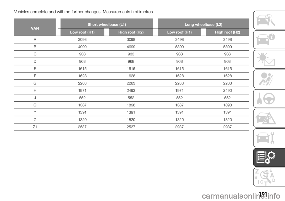
Vehicles complete and with no further changes. Measurements i millimetres
VANShort wheelbase (L1) Long wheelbase (L2)
Low roof (H1) High roof (H2) Low roof (H1) High roof (H2)
A 3098 3098 3498 3498
B
4999 4999 5399 5399
C 933 933 933 933
D 968 968 968 968
E 1615 1615 1615 1615
F 1628 1628 1628 1628
G 2283 2283 2283 2283
H 1971 2493 1971 2490
J 552 552 552 552
Q 1387 1898 1387 1898
Y 1391 1391 1391 1391
Z 1320 1820 1320 1820
Z1 2537 2537 2937 2937
191
Page 195 of 236

Vehicles complete and with no further changes. Measurements i millimetres
COMBI N1Short wheelbase (L1) Long wheelbase (L2)
Low roof (H1)
5/6 passengers
A 3098 3498
B 4999 5399
C 933 933
D 968 968
E 1615 1615
F 1628 1628
G 2283 2283
H 1971 1971
J 552 552
Q 1369 1369
Y 1391 1391
Z 1320 1320
Z1 1650 2050
193
Page 196 of 236
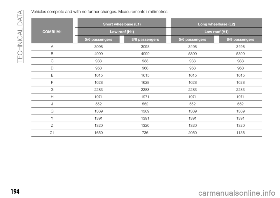
Vehicles complete and with no further changes. Measurements i millimetres
COMBI M1Short wheelbase (L1) Long wheelbase (L2)
Low roof (H1) Low roof (H1)
5/6 passengers 8/9 passengers 5/6 passengers 8/9 passengers
A 3098 3098 3498 3498
B 4999 4999 5399 5399
C 933 933 933 933
D 968 968 968 968
E 1615 1615 1615 1615
F 1628 1628 1628 1628
G 2283 2283 2283 2283
H 1971 1971 1971 1971
J 552 552 552 552
Q 1369 1369 1369 1369
Y 1391 1391 1391 1391
Z 1320 1320 1320 1320
Z1 1650 736 2050 1136
194
TECHNICAL DATA
Page 198 of 236
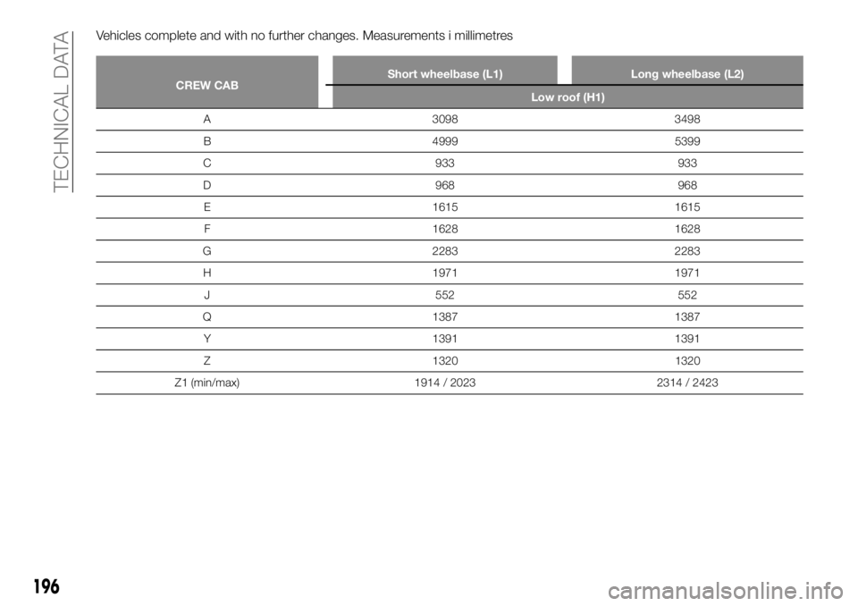
Vehicles complete and with no further changes. Measurements i millimetres
CREW CABShort wheelbase (L1) Long wheelbase (L2)
Low roof (H1)
A 3098 3498
B
4999 5399
C 933 933
D 968 968
E 1615 1615
F 1628 1628
G 2283 2283
H 1971 1971
J 552 552
Q 1387 1387
Y 1391 1391
Z 1320 1320
Z1 (min/max) 1914/ 2023 2314 / 2423
196
TECHNICAL DATA