steering FIAT TALENTO 2020 Owner handbook (in English)
[x] Cancel search | Manufacturer: FIAT, Model Year: 2020, Model line: TALENTO, Model: FIAT TALENTO 2020Pages: 236, PDF Size: 4.86 MB
Page 3 of 236
Dear Customer,
We would like to congratulate and thank you for choosing a Fiat Professional.
We have written this handbook to help you get to know all the features of your vehicle and use it in the best possible way.
Here you will find information, advice and important warnings regarding use of your vehicle and how to achieve the best
performance from the technical features of your Fiat Talento.
You are advised to read it right through before taking to the road for the first time, to become familiar with the controls and
above all with those concerning brakes, steering and gearbox; at the same time, you can understand the vehicle behaviour on
different road surfaces.
This document also provides a description of special features and tips, as well as essential information for the safe driving, care
and maintenance of your Fiat Talento over time.
In the attached Warranty Booklet you will also find a description of the Services that Fiat offers to its customers, the Warranty
Certificate and the detail of the terms and conditions for maintaining its validity.
We are sure that these will help you to get in touch with and appreciate your new vehicle and the service provided by the
people at Fiat Professional.
Enjoy reading. Happy motoring!
Page 5 of 236
USE OF THE OWNER HANDBOOK
OPERATING INSTRUCTIONS
Each time direction instructions (left/right or forwards/backwards) about the vehicle are given, these must be intended as
regarding an occupant in the driver's seat. Special cases not complying with this rule will be specified as appropriate in the text.
The figures in the Owner Handbook are provided by way of example only: this might imply that some details of the image do
not correspond to the actual arrangement of your vehicle. In addition, the Handbook has been conceived considering cars with
steering wheel on the left side; it is therefore possible that on cars with steering wheel on the right side, the position or
construction of some controls is not exactly mirror-like with respect to the figure.
To identify the chapter with the information needed you can consult the index at the end of this Owner Handbook.
Chapters can be rapidly identified with dedicated graphic tabs, at the side of each odd page. A few pages further there is a key
for getting to know the chapter order and the relevant symbols in the tabs. There is in any case a textual indication of the
current chapter at the side of each even page.
Page 13 of 236
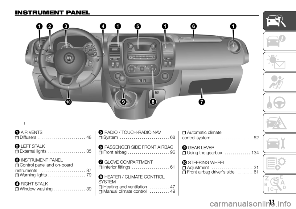
INSTRUMENT PANEL
AIR VENTSDiffusers........................ 48
LEFT STALKExternal lights................... 35
INSTRUMENT PANELControl panel and on-board
instruments....................... 87
Warning lights................... 79
RIGHT STALKWindow washing................ 39
RADIO / TOUCH-RADIO NAVSystem......................... 68
PASSENGER SIDE FRONT AIRBAGFront airbag..................... 96
GLOVE COMPARTMENTInterior fittings................... 61
HEATER / CLIMATE CONTROL
SYSTEM
Heating and ventilation.......... 47Manual climate control.......... 49
Automatic climate
control system..................... 52
GEAR LEVERUsing the gearbox............. 134
STEERING WHEELAdjustment..................... 31Front airbag driver's side........ 61
3
11
Page 14 of 236
KNOWING YOUR VEHICLE
In-depth knowledge of your new vehicle
starts here.
The handbook that you are reading
simply and directly explains how it is
made and how it works.
That’s why we advise you to read it
seated comfortably on board, so that
you can see what is described here for
yourself.THE KEYS.................13
DOORS...................20
HEADRESTS................26
SEATS....................27
STEERING WHEEL/POWER
STEERING.................31
START&STOP SYSTEM.........32
REAR VIEW MIRRORS.........34
EXTERNAL LIGHTS...........35
INTERIOR LIGHTS............38
WINDSCREEN / REAR WINDOW
WIPERS..................39
REFUELLING THE VEHICLE......42
AdBlue (Urea) ADDITIVE TANK....43
IGNITION DEVICE............45
CLIMATE CONTROL...........45
RADAR PARKING.............56
REAR CAMERA..............57
ELECTRIC WINDOWS..........59
ENGINE BONNET............60
INTERIOR FITTINGS...........61
MULTIMEDIA EQUIPMENT.......68
RADIO....................68
BAGGAGE COVER............69
CRUISE CONTROL
(constant speed regulator).......69
SPEED LIMITER..............72
PROTECTING THE
ENVIRONMENT..............73DIESEL VERSION
PARTICULARITIES............74
12
KNOWING YOUR VEHICLE
Page 33 of 236
24)When you reposition the single seats,
make sure they are locked in place. Make
sure the side safety belts are properly
locked in their housings.
25)Do not exchange seats 1 and 2.STEERING WHEEL/
POWER STEERING
STEERING WHEEL
ADJUSTMENT
26) 27) 28)
1)
Height and depth steering wheel
adjustment
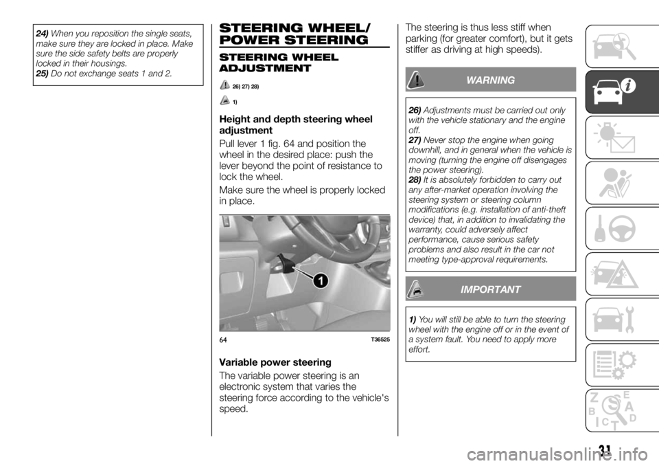
Pull lever 1 fig. 64 and position the
wheel in the desired place: push the
lever beyond the point of resistance to
lock the wheel.
Make sure the wheel is properly locked
in place.
Variable power steering
The variable power steering is an
electronic system that varies the
steering force according to the vehicle's
speed.The steering is thus less stiff when
parking (for greater comfort), but it gets
stiffer as driving at high speeds).
WARNING
26)Adjustments must be carried out only
with the vehicle stationary and the engine
off.
27)Never stop the engine when going
downhill, and in general when the vehicle is
moving (turning the engine off disengages
the power steering).
28)It is absolutely forbidden to carry out
any after-market operation involving the
steering system or steering column
modifications (e.g. installation of anti-theft
device) that, in addition to invalidating the
warranty, could adversely affect
performance, cause serious safety
problems and also result in the car not
meeting type-approval requirements.
IMPORTANT
1)You will still be able to turn the steering
wheel with the engine off or in the event of
a system fault. You need to apply more
effort.
64T36525
31
Page 39 of 236
IMPORTANT The table above contains
several examples. In all cases, adjust
the control A according to the vehicle
load to illuminate the road without
dazzling other drivers.
IMPORTANT If you are driving on the
left in a vehicle equipped for left hand
drive (or vice versa), you must adjust
the headlight orientation for the duration
of the visit.
Adjusting the headlights externally
Open the engine compartment and
identify the B fig. 72 printed near one of
the front lights.
For each light, turn screw 1 fig. 72 a
quarter turn towards the - with a
screwdriver to lower the lights.
Once the parking ends, return to the
original position: turn screw 1 a quarter
turn to the + to raise up the lights.DIRECTION INDICATORS
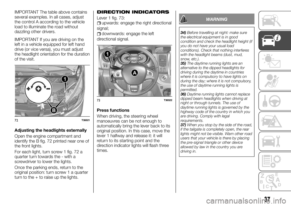
Lever 1 fig. 73:upwards: engage the right directional
signal;
downwards: engage the left
directional signal.
Press functions
When driving, the steering wheel
manoeuvres can be not enough to
automatically bring the lever back to its
original position. In this case, move the
lever 1 halfway and release it: it will
return to its starting point and the
direction indicator lights will flash three
times.
WARNING
34)Before travelling at night: make sure
the electrical equipment is in good
condition and check the headlight height (if
you do not have your usual load
conditions). Check that nothing interferes
with the headlight beams (dust, mud,
snow, etc.).
35)The daytime running lights are an
alternative to the dipped headlights for
driving during the daytime in countries
where it is compulsory to have lights on
during the day; where it is not compulsory,
the use of daytime running lights is
permitted.
36)Daytime running lights cannot replace
dipped beam headlights when driving at
night or through tunnels. The use of
daytime running lights is governed by the
highway code of the country in which you
are driving. Comply with legal
requirements.
37)When you stop by the side of the road,
if the tailgate is completely open, the rear
lights might not be visible. Warn other road
users that your vehicle is there by placing
the pre-signal triangle or other device
allowed by law in the country you are
driving in.
72T38821
73T36522
37
Page 47 of 236
IGNITION DEVICE
49) 50) 51) 52) 53)
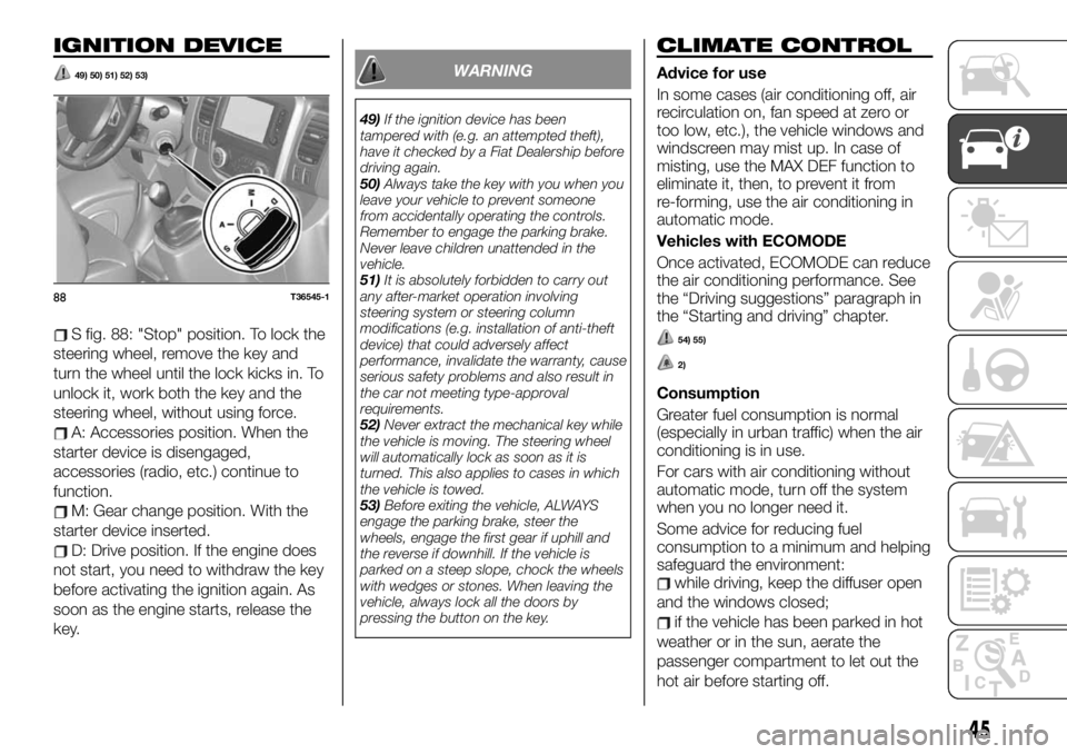
S fig. 88: "Stop" position. To lock the
steering wheel, remove the key and
turn the wheel until the lock kicks in. To
unlock it, work both the key and the
steering wheel, without using force.
A: Accessories position. When the
starter device is disengaged,
accessories (radio, etc.) continue to
function.
M: Gear change position. With the
starter device inserted.
D: Drive position. If the engine does
not start, you need to withdraw the key
before activating the ignition again. As
soon as the engine starts, release the
key.
WARNING
49)If the ignition device has been
tampered with (e.g. an attempted theft),
have it checked by a Fiat Dealership before
driving again.
50)Always take the key with you when you
leave your vehicle to prevent someone
from accidentally operating the controls.
Remember to engage the parking brake.
Never leave children unattended in the
vehicle.
51)It is absolutely forbidden to carry out
any after-market operation involving
steering system or steering column
modifications (e.g. installation of anti-theft
device) that could adversely affect
performance, invalidate the warranty, cause
serious safety problems and also result in
the car not meeting type-approval
requirements.
52)Never extract the mechanical key while
the vehicle is moving. The steering wheel
will automatically lock as soon as it is
turned. This also applies to cases in which
the vehicle is towed.
53)Before exiting the vehicle, ALWAYS
engage the parking brake, steer the
wheels, engage the first gear if uphill and
the reverse if downhill. If the vehicle is
parked on a steep slope, chock the wheels
with wedges or stones. When leaving the
vehicle, always lock all the doors by
pressing the button on the key.
CLIMATE CONTROL
Advice for use
In some cases (air conditioning off, air
recirculation on, fan speed at zero or
too low, etc.), the vehicle windows and
windscreen may mist up. In case of
misting, use the MAX DEF function to
eliminate it, then, to prevent it from
re-forming, use the air conditioning in
automatic mode.
Vehicles with ECOMODE
Once activated, ECOMODE can reduce
the air conditioning performance. See
the “Driving suggestions” paragraph in
the “Starting and driving” chapter.
54) 55)
2)
Consumption
Greater fuel consumption is normal
(especially in urban traffic) when the air
conditioning is in use.
For cars with air conditioning without
automatic mode, turn off the system
when you no longer need it.
Some advice for reducing fuel
consumption to a minimum and helping
safeguard the environment:
while driving, keep the diffuser open
and the windows closed;
if the vehicle has been parked in hot
weather or in the sun, aerate the
passenger compartment to let out the
hot air before starting off.
88T36545-1
45
Page 60 of 236
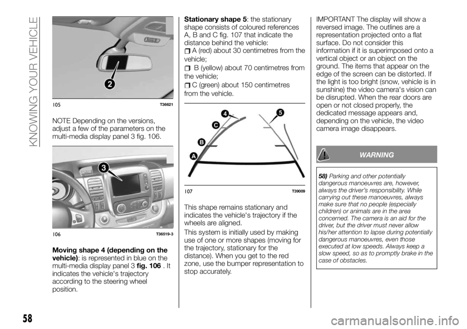
NOTE Depending on the versions,
adjust a few of the parameters on the
multi-media display panel 3 fig. 106.
Moving shape 4 (depending on the
vehicle): is represented in blue on the
multi-media display panel 3fig. 106.It
indicates the vehicle's trajectory
according to the steering wheel
position.Stationary shape 5: the stationary
shape consists of coloured references
A, B and C fig. 107 that indicate the
distance behind the vehicle:
A (red) about 30 centimetres from the
vehicle;
B (yellow) about 70 centimetres from
the vehicle;
C (green) about 150 centimetres
from the vehicle.
This shape remains stationary and
indicates the vehicle's trajectory if the
wheels are aligned.
This system is initially used by making
use of one or more shapes (moving for
the trajectory, stationary for the
distance). When you get to the red
zone, use the bumper representation to
stop accurately.IMPORTANT The display will show a
reversed image. The outlines are a
representation projected onto a flat
surface. Do not consider this
information if it is superimposed onto a
vertical object or an object on the
ground. The items that appear on the
edge of the screen can be distorted. If
the light is too bright (snow, vehicle is in
sunshine) the video camera's vision can
be disrupted. When the rear doors are
open or not closed properly, the
dedicated message appears and,
depending on the vehicle, the video
camera image disappears.
WARNING
58)Parking and other potentially
dangerous manoeuvres are, however,
always the driver’s responsibility. While
carrying out these manoeuvres, always
make sure that no people (especially
children) or animals are in the area
concerned. The camera is an aid for the
driver, but the driver must never allow
his/her attention to lapse during potentially
dangerous manoeuvres, even those
executed at low speeds. Always keep a
slow speed, so as to promptly brake in the
case of obstacles.
105T36621
106T36519-3
107T39009
58
KNOWING YOUR VEHICLE
Page 70 of 236
MULTIMEDIA
EQUIPMENT
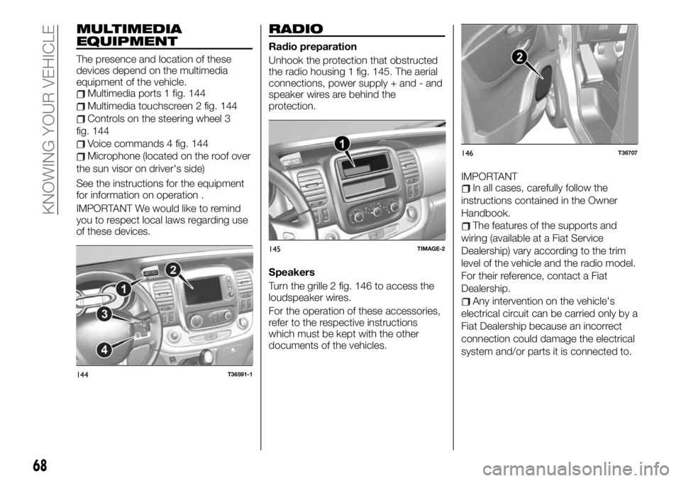
The presence and location of these
devices depend on the multimedia
equipment of the vehicle.
Multimedia ports 1 fig. 144
Multimedia touchscreen 2 fig. 144
Controls on the steering wheel 3
fig. 144
Voice commands 4 fig. 144
Microphone (located on the roof over
the sun visor on driver's side)
See the instructions for the equipment
for information on operation .
IMPORTANT We would like to remind
you to respect local laws regarding use
of these devices.
RADIO
Radio preparation
Unhook the protection that obstructed
the radio housing 1 fig. 145. The aerial
connections, power supply + and - and
speaker wires are behind the
protection.
Speakers
Turn the grille 2 fig. 146 to access the
loudspeaker wires.
For the operation of these accessories,
refer to the respective instructions
which must be kept with the other
documents of the vehicles.IMPORTANT
In all cases, carefully follow the
instructions contained in the Owner
Handbook.
The features of the supports and
wiring (available at a Fiat Service
Dealership) vary according to the trim
level of the vehicle and the radio model.
For their reference, contact a Fiat
Dealership.
Any intervention on the vehicle's
electrical circuit can be carried only by a
Fiat Dealership because an incorrect
connection could damage the electrical
system and/or parts it is connected to.
144T36591-1
145TIMAGE-2
146T36707
68
KNOWING YOUR VEHICLE
Page 95 of 236
adjust the head restraint. For
maximum safety, the distance between
the head and headrest must be
minimum;
adjust cushion (seat) height. This
adjustment optimises visibility;
adjust the steering wheel.
ADJUSTING THE SEAT BELTS
Sit firmly on the backrest.
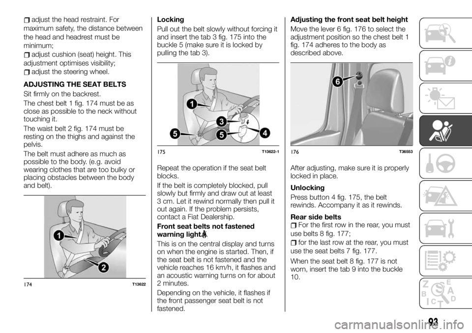
The chest belt 1 fig. 174 must be as
close as possible to the neck without
touching it.
The waist belt 2 fig. 174 must be
resting on the thighs and against the
pelvis.
The belt must adhere as much as
possible to the body. (e.g. avoid
wearing clothes that are too bulky or
placing obstacles between the body
and belt).Locking
Pull out the belt slowly without forcing it
and insert the tab 3 fig. 175 into the
buckle 5 (make sure it is locked by
pulling the tab 3).
Repeat the operation if the seat belt
blocks.
If the belt is completely blocked, pull
slowly but firmly and draw out at least
3 cm. Let it rewind normally then pull it
out again. If the problem persists,
contact a Fiat Dealership.
Front seat belts not fastened
warning light
This is on the central display and turns
on when the engine is started. Then, if
the seat belt is not fastened and the
vehicle reaches 16 km/h, it flashes and
an acoustic warning turns on for about
2 minutes.
Depending on the vehicle, it flashes if
the front passenger seat belt is not
fastened.Adjusting the front seat belt height
Move the lever 6 fig. 176 to select the
adjustment position so the chest belt 1
fig. 174 adheres to the body as
described above.
After adjusting, make sure it is properly
locked in place.
Unlocking
Press button 4 fig. 175, the belt
rewinds. Accompany it as it rewinds.
Rear side belts
For the first row in the rear, you must
use belts 8 fig. 177;
for the last row at the rear, you must
use the seat belts 7 fig. 177.
When the seat belt 8 fig. 177 is not
worn, insert the tab 9 into the buckle
10.
174T13622
175T13622-1176T36553
93