height FIAT TALENTO 2021 Owner handbook (in English)
[x] Cancel search | Manufacturer: FIAT, Model Year: 2021, Model line: TALENTO, Model: FIAT TALENTO 2021Pages: 236, PDF Size: 4.86 MB
Page 25 of 236
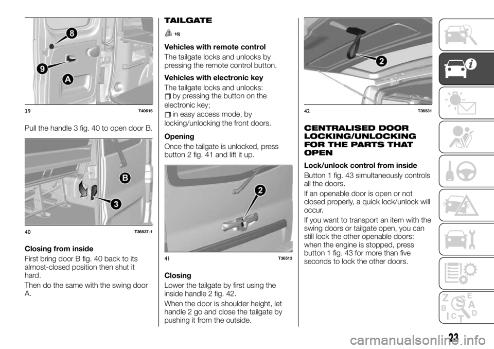
Pull the handle 3 fig. 40 to open door B.
Closing from inside
First bring door B fig. 40 back to its
almost-closed position then shut it
hard.
Then do the same with the swing door
A.
TAILGATE
16)
Vehicles with remote control
The tailgate locks and unlocks by
pressing the remote control button.
Vehicles with electronic key
The tailgate locks and unlocks:
by pressing the button on the
electronic key;
in easy access mode, by
locking/unlocking the front doors.
Opening
Once the tailgate is unlocked, press
button 2 fig. 41 and lift it up.
Closing
Lower the tailgate by first using the
inside handle 2 fig. 42.
When the door is shoulder height, let
handle 2 go and close the tailgate by
pushing it from the outside.
CENTRALISED DOOR
LOCKING/UNLOCKING
FOR THE PARTS THAT
OPEN
Lock/unlock control from inside
Button 1 fig. 43 simultaneously controls
all the doors.
If an openable door is open or not
closed properly, a quick lock/unlock will
occur.
If you want to transport an item with the
swing doors or tailgate open, you can
still lock the other openable doors:
when the engine is stopped, press
button 1 fig. 43 for more than five
seconds to lock the other doors.
39T40615
40T36537-1
41T36513
42T36531
23
Page 28 of 236
Also make sure the lock system was
not accidentally disabled.
In case it was disabled, re-enable it
after disconnecting and reconnecting
the starter device.
WARNING
3)For safety reasons, make sure all the
doors are well closed before setting out.
4)Never leave the vehicle with the remote
or electronic key inside.
5)For safety reasons, always open/close
doors when the vehicle is stopped.
6)NEVER leave children unattended inside
the vehicle, let alone leave it with the doors
unlocked in a place that children can
access easily. Children may seriously, or
even fatally, injure themselves. Also ensure
that children do not inadvertently operate
the parking brake or the brake pedal.
7)Opening or closing the door, as for all
opening parts of the vehicle, must be done
keeping in mind the precautions for use
concerning this operation: check that there
is no one, no part of a body, an animal or
object that could come into contact during
this manoeuvre. Only use the inside and
outside handles to manoeuvre the door.
Use caution in both opening and closing
the doors. Caution: when the vehicle is
parked on an incline, open or close the
door carefully until it locks in place. Always
make sure the sliding door is completely
closed before the vehicle starts moving.
8)Before opening a door, ensure that you
can do it in conditions of safety.9)You must not open the left-hand sliding
side door with the fuel flap open while
refuelling. Check that the fuel flap is closed
while opening/closing the sliding side door
to avoid damage.
10)Do not leave the sliding side door open
when the vehicle is parked on a gradient. A
knock could release the latch leaving the
door free to move forward.
11)Before leaving the vehicle parked with
sliding doors open, always check that the
latch is engaged.
12)Always use this device when carrying
children.
13)The spring-loaded system is designed
for optimum usage. Accidental knocks or a
strong gust of wind may release the
springs, forcing the doors to close.
14)When closing, shut the right hand
swing door fully before you close the left
hand swing door. Never shut the two doors
at the same time.
15)In case of wind, do not leave the rear
swing doors open. Risk of injury.
16)When you stop by the side of the road,
if the tailgate is completely open, the rear
lights might not be visible. Warn other road
users that your vehicle is there by placing
the pre-signal triangle or other device
allowed by law in the country you are
driving in.
HEADRESTS
FRONT HEADREST
17)
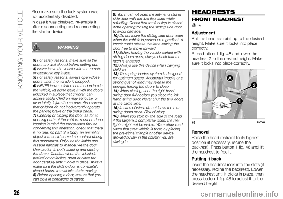
Adjustment
Pull the head restraint up to the desired
height. Make sure it locks into place
correctly.
Press button 1 fig. 48 and lower the
headrest 2 to the desired height. Make
sure it locks into place correctly.
Removal
Raise the head restraint to its highest
position (if necessary, recline the
backrest). Press button 1 fig. 48 and lift
the headrest to free it.
Putting it back
Insert the headrest rods into the slots (if
necessary, recline the backrest). Lower
the headrest until it clicks in place, then
press button 1 fig. 48 to adjust it to the
desired height.
48T36589
26
KNOWING YOUR VEHICLE
Page 29 of 236
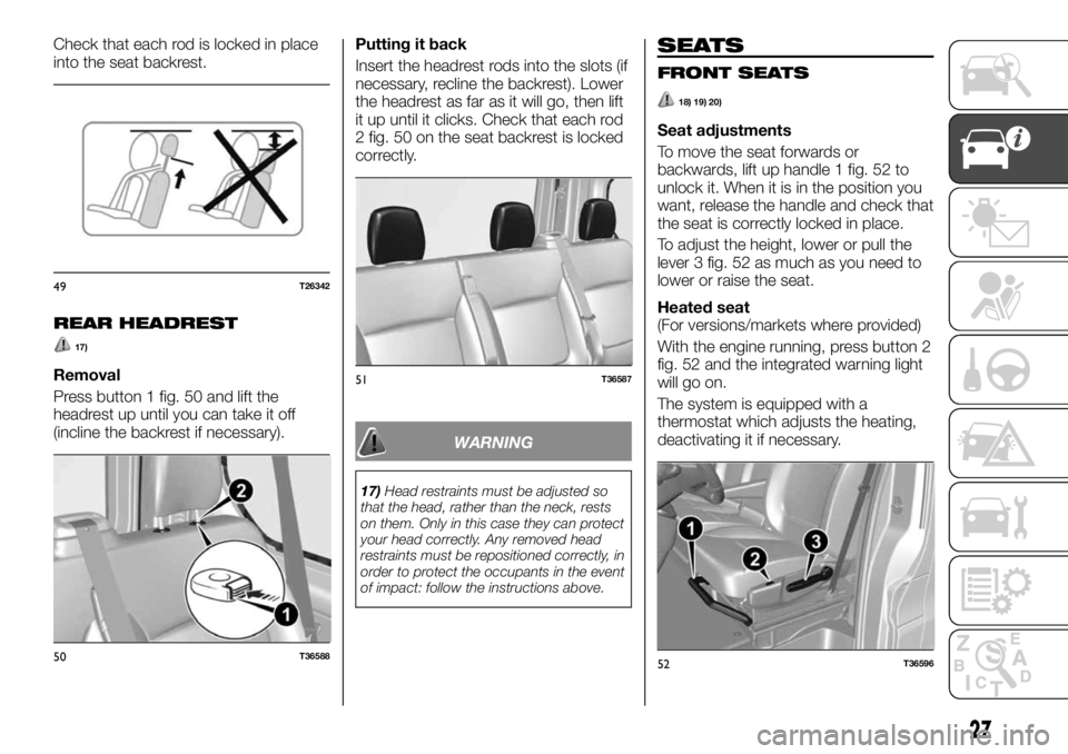
Check that each rod is locked in place
into the seat backrest.
REAR HEADREST
17)
Removal
Press button 1 fig. 50 and lift the
headrest up until you can take it off
(incline the backrest if necessary).Putting it back
Insert the headrest rods into the slots (if
necessary, recline the backrest). Lower
the headrest as far as it will go, then lift
it up until it clicks. Check that each rod
2 fig. 50 on the seat backrest is locked
correctly.
WARNING
17)Head restraints must be adjusted so
that the head, rather than the neck, rests
on them. Only in this case they can protect
your head correctly. Any removed head
restraints must be repositioned correctly, in
order to protect the occupants in the event
of impact: follow the instructions above.
SEATS
FRONT SEATS
18) 19) 20)
Seat adjustments
To move the seat forwards or
backwards, lift up handle 1 fig. 52 to
unlock it. When it is in the position you
want, release the handle and check that
the seat is correctly locked in place.
To adjust the height, lower or pull the
lever 3 fig. 52 as much as you need to
lower or raise the seat.
Heated seat
(For versions/markets where provided)
With the engine running, press button 2
fig. 52 and the integrated warning light
will go on.
The system is equipped with a
thermostat which adjusts the heating,
deactivating it if necessary.
49T26342
50T36588
51T36587
52T36596
27
Page 33 of 236
24)When you reposition the single seats,
make sure they are locked in place. Make
sure the side safety belts are properly
locked in their housings.
25)Do not exchange seats 1 and 2.STEERING WHEEL/
POWER STEERING
STEERING WHEEL
ADJUSTMENT
26) 27) 28)
1)
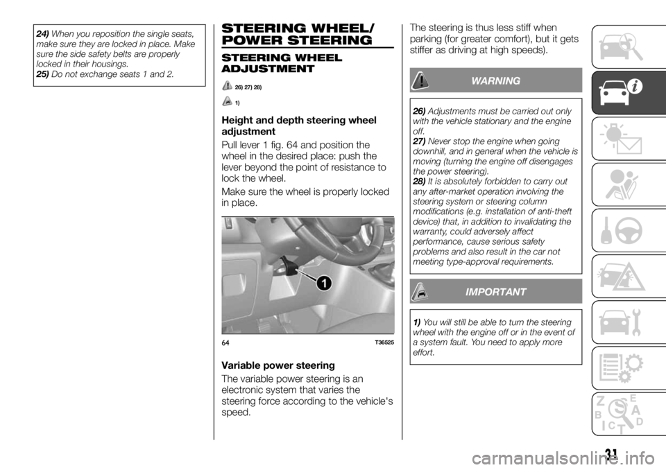
Height and depth steering wheel
adjustment
Pull lever 1 fig. 64 and position the
wheel in the desired place: push the
lever beyond the point of resistance to
lock the wheel.
Make sure the wheel is properly locked
in place.
Variable power steering
The variable power steering is an
electronic system that varies the
steering force according to the vehicle's
speed.The steering is thus less stiff when
parking (for greater comfort), but it gets
stiffer as driving at high speeds).
WARNING
26)Adjustments must be carried out only
with the vehicle stationary and the engine
off.
27)Never stop the engine when going
downhill, and in general when the vehicle is
moving (turning the engine off disengages
the power steering).
28)It is absolutely forbidden to carry out
any after-market operation involving the
steering system or steering column
modifications (e.g. installation of anti-theft
device) that, in addition to invalidating the
warranty, could adversely affect
performance, cause serious safety
problems and also result in the car not
meeting type-approval requirements.
IMPORTANT
1)You will still be able to turn the steering
wheel with the engine off or in the event of
a system fault. You need to apply more
effort.
64T36525
31
Page 39 of 236
IMPORTANT The table above contains
several examples. In all cases, adjust
the control A according to the vehicle
load to illuminate the road without
dazzling other drivers.
IMPORTANT If you are driving on the
left in a vehicle equipped for left hand
drive (or vice versa), you must adjust
the headlight orientation for the duration
of the visit.
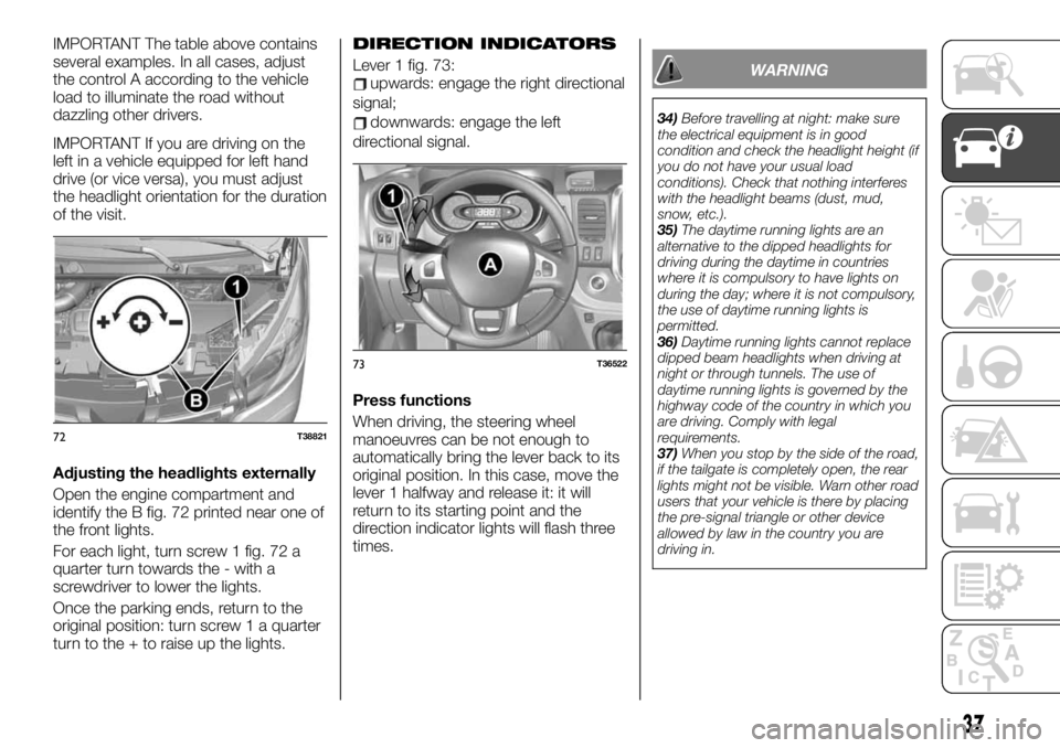
Adjusting the headlights externally
Open the engine compartment and
identify the B fig. 72 printed near one of
the front lights.
For each light, turn screw 1 fig. 72 a
quarter turn towards the - with a
screwdriver to lower the lights.
Once the parking ends, return to the
original position: turn screw 1 a quarter
turn to the + to raise up the lights.DIRECTION INDICATORS
Lever 1 fig. 73:upwards: engage the right directional
signal;
downwards: engage the left
directional signal.
Press functions
When driving, the steering wheel
manoeuvres can be not enough to
automatically bring the lever back to its
original position. In this case, move the
lever 1 halfway and release it: it will
return to its starting point and the
direction indicator lights will flash three
times.
WARNING
34)Before travelling at night: make sure
the electrical equipment is in good
condition and check the headlight height (if
you do not have your usual load
conditions). Check that nothing interferes
with the headlight beams (dust, mud,
snow, etc.).
35)The daytime running lights are an
alternative to the dipped headlights for
driving during the daytime in countries
where it is compulsory to have lights on
during the day; where it is not compulsory,
the use of daytime running lights is
permitted.
36)Daytime running lights cannot replace
dipped beam headlights when driving at
night or through tunnels. The use of
daytime running lights is governed by the
highway code of the country in which you
are driving. Comply with legal
requirements.
37)When you stop by the side of the road,
if the tailgate is completely open, the rear
lights might not be visible. Warn other road
users that your vehicle is there by placing
the pre-signal triangle or other device
allowed by law in the country you are
driving in.
72T38821
73T36522
37
Page 95 of 236
adjust the head restraint. For
maximum safety, the distance between
the head and headrest must be
minimum;
adjust cushion (seat) height. This
adjustment optimises visibility;
adjust the steering wheel.
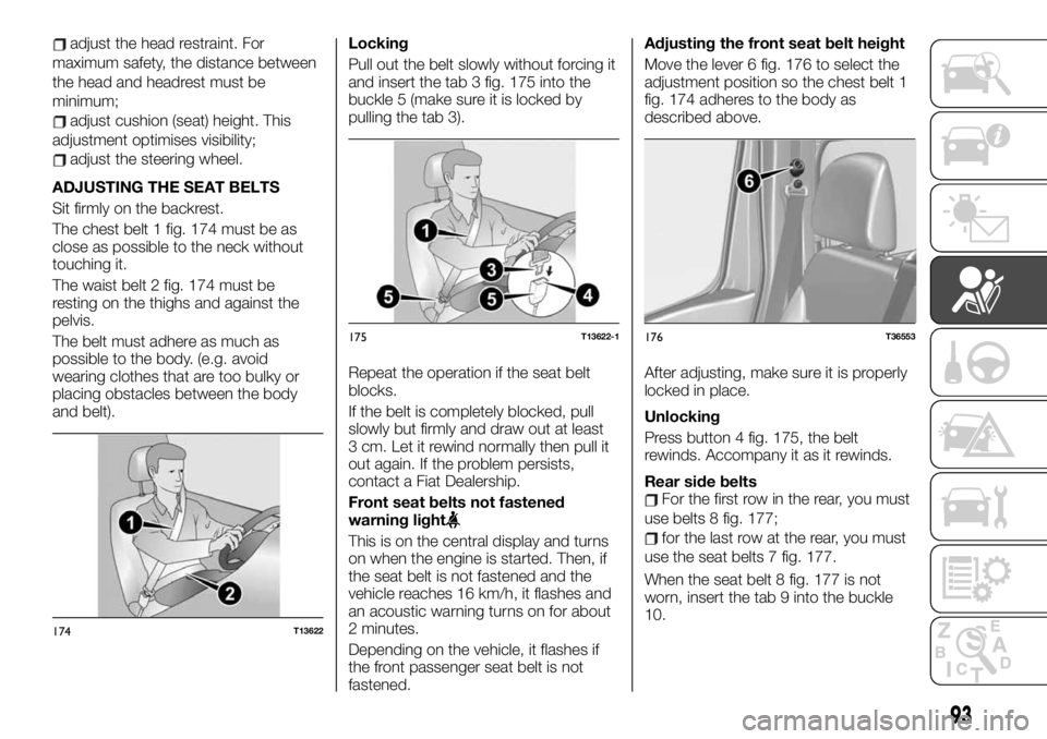
ADJUSTING THE SEAT BELTS
Sit firmly on the backrest.
The chest belt 1 fig. 174 must be as
close as possible to the neck without
touching it.
The waist belt 2 fig. 174 must be
resting on the thighs and against the
pelvis.
The belt must adhere as much as
possible to the body. (e.g. avoid
wearing clothes that are too bulky or
placing obstacles between the body
and belt).Locking
Pull out the belt slowly without forcing it
and insert the tab 3 fig. 175 into the
buckle 5 (make sure it is locked by
pulling the tab 3).
Repeat the operation if the seat belt
blocks.
If the belt is completely blocked, pull
slowly but firmly and draw out at least
3 cm. Let it rewind normally then pull it
out again. If the problem persists,
contact a Fiat Dealership.
Front seat belts not fastened
warning light
This is on the central display and turns
on when the engine is started. Then, if
the seat belt is not fastened and the
vehicle reaches 16 km/h, it flashes and
an acoustic warning turns on for about
2 minutes.
Depending on the vehicle, it flashes if
the front passenger seat belt is not
fastened.Adjusting the front seat belt height
Move the lever 6 fig. 176 to select the
adjustment position so the chest belt 1
fig. 174 adheres to the body as
described above.
After adjusting, make sure it is properly
locked in place.
Unlocking
Press button 4 fig. 175, the belt
rewinds. Accompany it as it rewinds.
Rear side belts
For the first row in the rear, you must
use belts 8 fig. 177;
for the last row at the rear, you must
use the seat belts 7 fig. 177.
When the seat belt 8 fig. 177 is not
worn, insert the tab 9 into the buckle
10.
174T13622
175T13622-1176T36553
93
Page 103 of 236
Booster seats
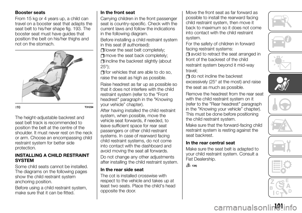
From 15 kg or 4 years up, a child can
travel on a booster seat that adapts the
seat belt to his/her shape fig. 193. The
booster seat must have guides that
position the belt on his/her thighs and
not on the stomach.
The height-adjustable backrest and
seat belt track is recommended to
position the belt at the centre of the
shoulder. It must never rest on the neck
or arm. Choose an encompassing child
restraint system for better side
protection.
INSTALLING A CHILD RESTRAINT
SYSTEM
Some child seats cannot be installed.
The diagrams on the following pages
show the child restraint system
anchoring position.
Before using a child restraint system,
make sure that it can be fitted.In the front seat
Carrying children in the front passenger
seat is country-specific. Check with the
current laws and follow the indications
in the following diagram.
Before installing a child restraint system
in this seat (if authorised):
lower the seat belt completely;
move the seat back completely;
incline the backrest slightly (about
25°);
for vehicles that are able to do so,
raise the seat as high as possible.
Raise headrest as far up as possible so
that it does not interfere with the child
restraint system (refer to the "Front
headrest" paragraph in the "Knowing
your vehicle” chapter).
After having installed the child restraint
system, when possible, move the
vehicle seat forwards, if needed, to
leave sufficient space for rear seat
passengers or other child restraint
systems. In case of rearward facing
child restraint systems, do not come
into contact with the dashboard and
avoid moving the seat all forwards.
Do not change any other adjustments
after installing the child restraint system.
In the rear side seat
The cot is installed crosswise with
respect to the vehicle and takes up at
least two seats. Place the child's head
opposite the door.Move the front seat as far forward as
possible to install the rearward facing
child restraint system, then move it
back to maximum so it does not come
into contact with the child restraint
system.
For the safety of children in forward
facing restraint systems:
avoid to retract the seat arranged in
front of the backrest of the child
restraint system beyond it mid-way
travel;
do not incline the backrest
excessively (25° at the most) and raise
the seat as much as possible.
Remove the headrest from the rear seat
with the child restraint system on it
(refer to the "Rear headrest" paragraph
in the "Knowing your vehicle” chapter).
This must be done before positioning
the child restraint system.
Make sure that the forward-facing child
restraint system is resting against the
seat backrest.
In the rear central seat
Make sure the seat belt is adapted to
your child restraint system. Consult a
Fiat Dealership.
134)
193T31234
101
Page 116 of 236
ISOFIX FASTENING
SYSTEM
Authorised child seats are approved
according to the ECE-R44 law in one of
the three following cases:
universal ISOFIX with 3 couplings
facing forward;
semi-universal ISOFIX with
2 couplings;
specific.
For the last two, check that your child
restraint system can be installed by
referring to the list of compatible
vehicles.
Fit the child restraint system with the
ISOFIX anchors, where provided. The
ISOFIX system ensures simple, fast and
safe installation.
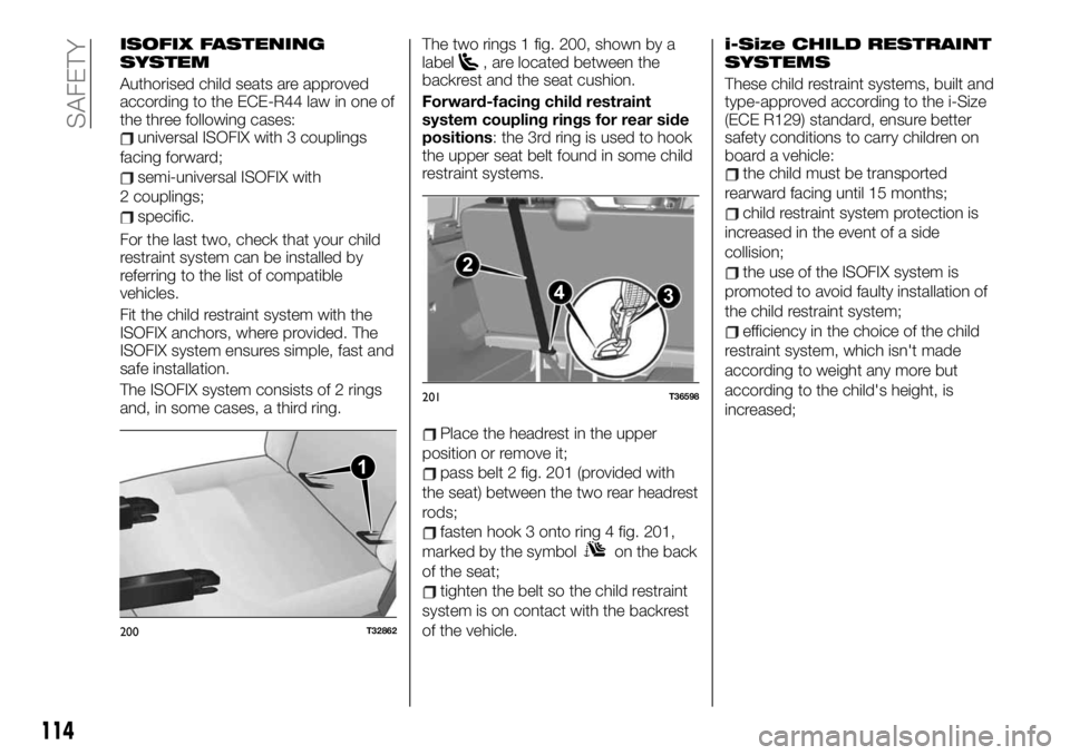
The ISOFIX system consists of 2 rings
and, in some cases, a third ring.The two rings 1 fig. 200, shown by a
label
, are located between the
backrest and the seat cushion.
Forward-facing child restraint
system coupling rings for rear side
positions: the 3rd ring is used to hook
the upper seat belt found in some child
restraint systems.
Place the headrest in the upper
position or remove it;
pass belt 2 fig. 201 (provided with
the seat) between the two rear headrest
rods;
fasten hook 3 onto ring 4 fig. 201,
marked by the symbol
on the back
of the seat;
tighten the belt so the child restraint
system is on contact with the backrest
of the vehicle.
i-Size CHILD RESTRAINT
SYSTEMS
These child restraint systems, built and
type-approved according to the i-Size
(ECE R129) standard, ensure better
safety conditions to carry children on
board a vehicle:
the child must be transported
rearward facing until 15 months;
child restraint system protection is
increased in the event of a side
collision;
the use of the ISOFIX system is
promoted to avoid faulty installation of
the child restraint system;
efficiency in the choice of the child
restraint system, which isn't made
according to weight any more but
according to the child's height, is
increased;
1
200T32862
2
3 4
201T36598
114
SAFETY
Page 137 of 236
WARNING
156)Never leave children unattended in
the vehicle. In addition, always remove the
ignition key when leaving the vehicle and
take it out with you.
157)For cars equipped with a front
armrest, lift it up to ensure that it does not
interfere with the action of the handbrake.
IMPORTANT
27)Depending on the slope and/or load,
you may need to tighten the brake another
two clicks.
28)When driving, check that the handbrake
is completely lowered and disengaged (the
red light is off): you could overheat or
deteriorate it.29)Following a collision with a kerb, a high
step, a stone post or other types of urban
features, have your vehicle checked by the
Fiat Dealership to avoid any risk of
accident: you may have damaged an axle
shaft, the steering gear or other part.
INSTALLING THE
TOW HOOK
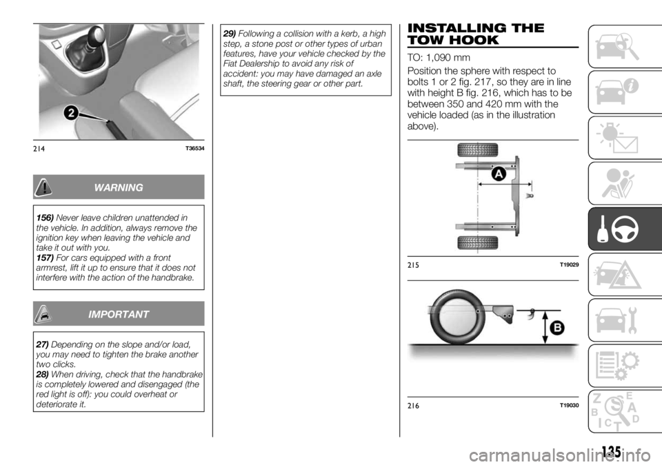
TO: 1,090 mm
Position the sphere with respect to
bolts 1 or 2 fig. 217, so they are in line
with height B fig. 216, which has to be
between 350 and 420 mm with the
vehicle loaded (as in the illustration
above).
214T36534
215T19029
216T19030
135
Page 200 of 236
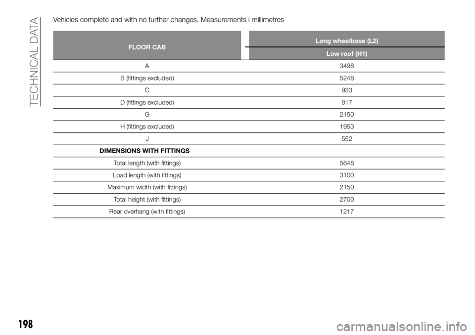
Vehicles complete and with no further changes. Measurements i millimetres
FLOOR CABLong wheelbase (L2)
Low roof (H1)
A 3498
B (fittings excluded) 5248
C 933
D (fittings excluded) 817
G 2150
H (fittings excluded) 1953
J 552
DIMENSIONS WITH FITTINGS
Total length (with fittings) 5648
Load length (with fittings) 3100
Maximum width (with fittings) 2150
Total height (with fittings) 2700
Rear overhang (with fittings) 1217
198
TECHNICAL DATA