coolant temperature FIAT TEMPRA 1988 Service And Repair Manual
[x] Cancel search | Manufacturer: FIAT, Model Year: 1988, Model line: TEMPRA, Model: FIAT TEMPRA 1988Pages: 171, PDF Size: 18.05 MB
Page 7 of 171
Fluid levels (if included) are monitored by LEDs f, o and
p, indicating the levels of the fluid reservoirs.
A red LED illuminates at the position on the check panel
corresponding to a side door or a hatchback/tailgate
that is not properly closed.
SIDE AND TAIL LIGHTS
When the side and tail lights are turned on, the check
panel monitors the light bulbs, fuses and circuits.
• LED g monitors the front side lights.
• LED i monitors the tail lights.
If one of the two fuses protecting the following bulbs
blows, LEDs g, i, and m illuminate.
NUMBER PLATE LIGHTS
• LED m indicates when one or both of the number
plate light bulbs have burnt out.
REAR FOG LIGHTS
• When the fog-guard lights are turned on, LED h
monitors the light bulbs.
• When the fuse blows or a circuit malfunction occurs,
LED h illuminates, but not the panel indicator.
STOP LIGHTS
If one or both stop lights burn out, the fuse blows or a
circuit malfunction occurs, LED I or n illuminates when
braking.
• LED n monitors the left stop light.
• LED I monitors the right stop light.
If both bulbs burn out at the same time or brake pedal
switch malfunction occurs, both LEDs I and n
illuminate.
ENGINE OIL LEVEL
• LED f illuminates when the engine oil level is low (key
at MAR,engine not running).
The oil level monitoring system does not operate when
the engine is running. If the oil level warning LED
illuminates when driving, a circuit sensor malfunction
has occurred.
When starting the car on a hill or within 10 minutes of
switching off the engine the warning light may
illuminate (event will be stored in system memory). Start
the engine again on level ground to ensure the oil level
is sufficient.
COOLANT
A low coolant level is indicated by LED o (key at MAR).
The LED also illuminates when a sensor or circuit
malfunction occurs.
WINDSCREEN AND REAR SCREEN WASH LEVELS
• LED p illuminates (key at MAR) when the level in the
windscreen or rear screen wash reservoirs are low.
• The LED also indicates when a circuit or sensor
malfunction occurs.
• 5. HE ATI IMG AMD VENTILATION
CONTROLS
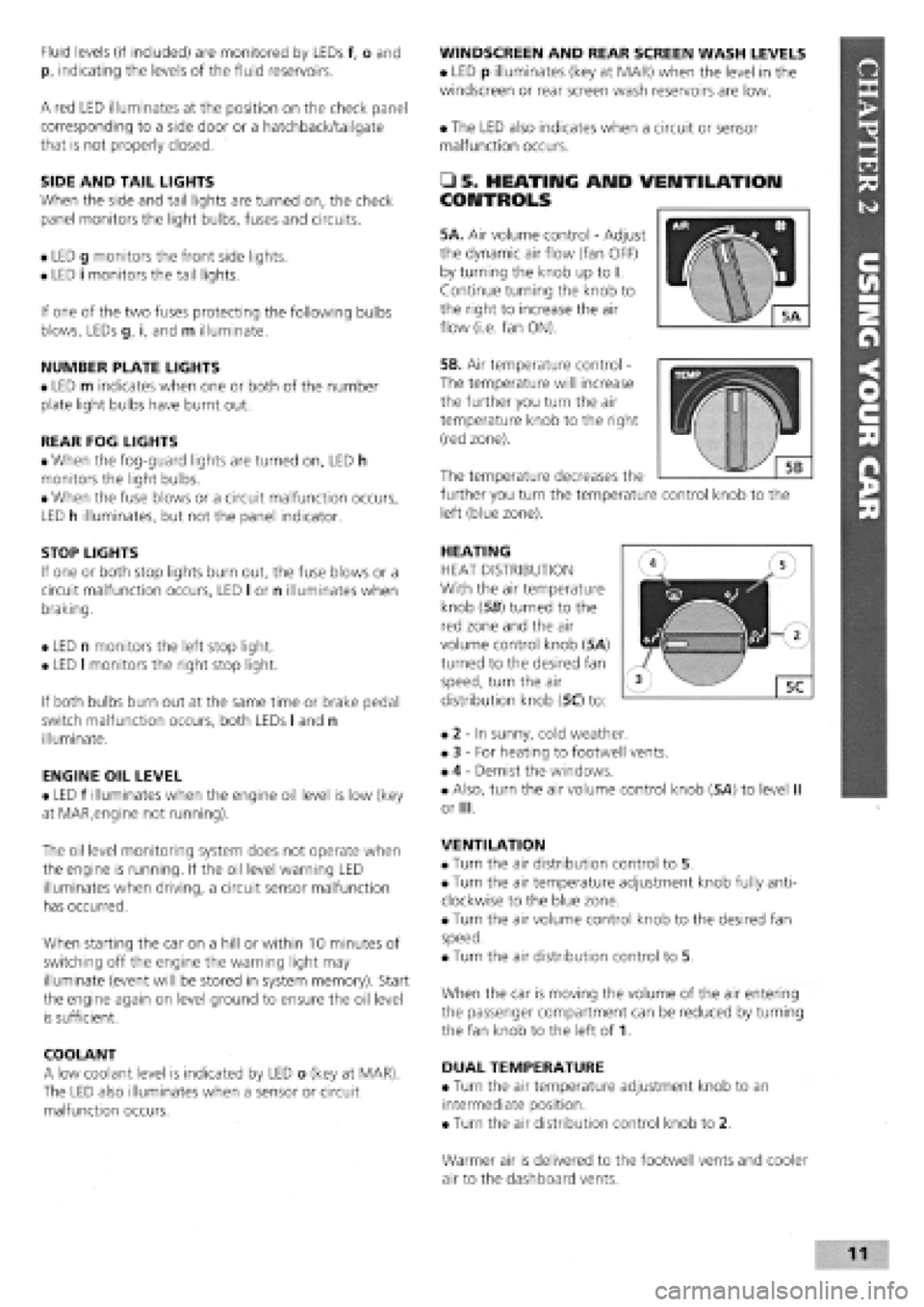
5A. Air volume control
-
Adjust
the dynamic air flow (fan OFF)
by turning the knob up to I.
Continue turning the knob to
the right to increase the air
flow (i.e. fan ON).
5B. Air temperature control -
The temperature will increase
the further you turn the air
temperature knob to the right
(red zone).
HEATING
HEAT DISTRIBUTION
With the air temperature
knob (56) turned to the
red zone and the air
volume control knob (5A)
turned to the desired fan
speed, turn the air
distribution knob (5C) to:
• 2
-
In sunny, cold weather.
• 3
-
For heating to footwell vents.
• 4
-
Demist the windows.
• Also, turn the air volume control knob (5A) to level II
or III.
VENTILATION
• Turn the air distribution control to 5.
• Turn the air temperature adjustment knob fully anti-
clockwise to the blue zone.
• Turn the air volume control knob to the desired fan
speed.
• Turn the air distribution control to 5.
When the car is moving the volume of the air entering
the passenger compartment can be reduced by turning
the fan knob to the left of 1.
DUAL TEMPERATURE
• Turn the air temperature adjustment knob to an
intermediate position.
• Turn the air distribution control knob to 2.
The temperature decreases the
further you turn the temperature control knob to the
left (blue zone).
Warmer air is delivered to the footwell vents and cooler
air to the dashboard vents.
Page 19 of 171
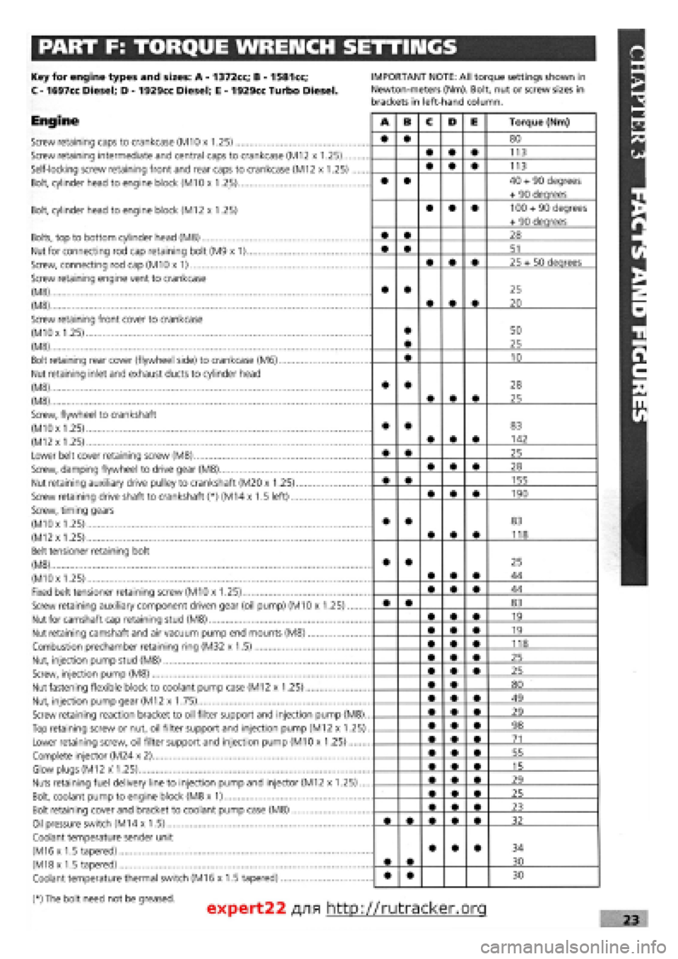
PART F: TORQUE WRENCH SETTINGS
Key for engine types and sizes: A
-
1372cc; B
-
1581cc;
C
-
1697cc Diesel; D
-
1929cc Diesel; E
-
1929cc Turbo Diesel.
Engine
Screw retaining caps to crankcase (M10 x 1.25)
Screw retaining intermediate and central caps to crankcase (M12 x 1.25)...
Self-locking screw retaining front and rear caps to crankcase (M12 x 1.25)
Bolt, cylinder head to engine block (M10 x 1.25)
IMPORTANT NOTE: All torque settings shown in
Newton-meters (Nm). Bolt, nut or screw sizes in
brackets in left-hand column.
Bolt, cylinder head to engine block (M12 x 1.25)
Bolts, top to bottom cylinder head (M8)
Nut for connecting rod cap retaining bolt (M9 x 1)
Screw, connecting rod cap (M10 x 1)
Screw retaining engine vent to crankcase
(M8)
(M8)
Screw retaining front cover to crankcase
(MlOx 1.25)
(M8)
Bolt retaining rear cover (flywheel side) to crankcase (M6)
Nut retaining inlet and exhaust ducts to cylinder head
(M8)
(M8)
Screw, flywheel to crankshaft
(M10x 1.25)
(M12
x
1.25)
Lower belt cover retaining screw (M8)
Screw, damping flywheel to drive gear (M8)
Nut retaining auxiliary drive pulley to crankshaft (M20 x 1.25)
Screw retaining drive shaft to crankshaft (*) (M14 x 1.5 left)
Screw, timing gears
(M10x 1.25)
(M12x 1.25)
Belt tensioner retaining bolt
(M8)
(M10x 1.25)
Fixed belt tensioner retaining screw (M10 x 1.25)
Screw retaining auxiliary component driven gear (oil pump) (M10 x 1.25)
Nut for camshaft cap retaining stud (M8)
Nut retaining camshaft and air vacuum pump end mounts (M8)
Combustion prechamber retaining ring (M32 x 1.5)
Nut, injection pump stud (M8)
Screw, injection pump (M8)
Nut fastening flexible block to coolant pump case (M12 x 1.25)
Nut, injection pump gear (M12 x 1.75)
Screw retaining reaction bracket to oil filter support and injection pump (M8).
Top retaining screw or nut, oil filter support and injection pump (M12 x 1.25)
Lower retaining screw, oil filter support and injection pump (M10 x 1.25)
Complete injector (M24 x 2)
Glow plugs (M12 x 1.25)
Nuts retaining fuel delivery line to injection pump and injector (M12 x 1.25)...
Bolt, coolant pump to engine block (M8 x 1)
Bolt retaining cover and bracket to coolant pump case (M8)
Oil pressure switch (M14 x 1.5)
Coolant temperature sender unit
(M16 x 1.5 tapered)
(M18x 1.5 tapered)
Coolant temperature thermal switch (M16 x 1.5 tapered)
(*) The bolt need not be greased.
A B C D E Torque (Nm)
• • 80
• • • 113
• • • 113
• • 40
+
90 degrees
+ 90 deqrees
• • • 100
+
90 degrees
+ 90 deqrees
• • 28
• • 51
• • • 25 + 50 deqrees
• •
• • •
25
20
• • 50
25
• 10
• •
• • •
28
25
• •
• • •
83
142
• • 25
• • • 28
• • 155
• • • 190
• •
• • •
83
118
• •
• • •
25
44
• • • 44
• • 83
• • • 19
• • • 19
• • • 118
• • • 25
• • • 25
• • 80
• • • 49
• • • 29
• • • 98
• • • 71
• • • 55
• • • 15
• • • 29
• • • 25
• • • 23
32
• •
• • • 34
30
• • 30
expert22 fl/i* http://rutracker.org 23
Page 64 of 171
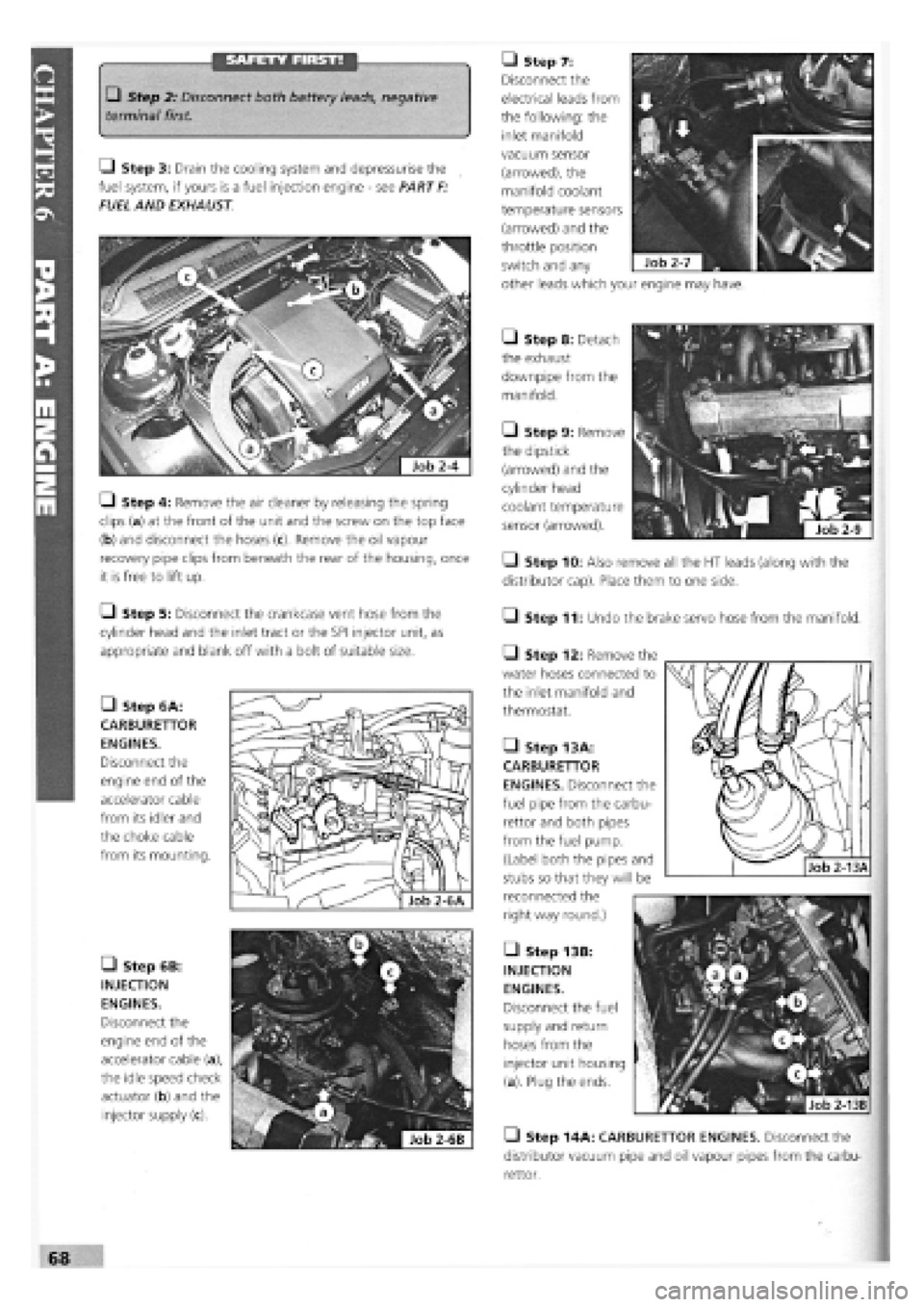
SAFETY FIRST! • Step 7:
Disconnect the
electrical leads from
the following: the
inlet manifold
• Step 2: Disconnect both battery leads, negative
terminal first.
Q Step 3: Drain the cooling system and depressurise the
fuel system, if yours is a fuel injection engine
-
see PART
F:
FUEL AND EXHAUST
• Step 6B:
INJECTION
ENGINES.
Disconnect the
engine end of the
accelerator cable (a),
the idle speed check
actuator (b) and the
injector supply (c).
• Step 8: Detach
the exhaust
downpipe from the
manifold.
• Step 9: Remove
the dipstick
(arrowed) and the
cylinder head
coolant temperature
sensor (arrowed).
• Step 10: Also remove all the HT leads (along with the
distributor cap). Place them to one side.
• Step 11: Undo the brake servo hose from the manifold.
Q Step 4: Remove the air cleaner by releasing the spring
clips (a) at the front of the unit and the screw on the top face
(b) and disconnect the hoses
recovery pipe clips from beneath the rear of the housing, once
it is free to lift up.
Q Step 5: Disconnect the crankcase vent hose from the
cylinder head and the inlet tract or the SPI injector unit, as
appropriate and blank off with a bolt of suitable size.
• Step 6A:
CARBURETTOR
ENGINES.
Disconnect the
engine end of the
accelerator cable
from its idler and
the choke cable
from its mounting.
Q Step 12: Remove the
water hoses connected to
the inlet manifold and
thermostat.
• Step 13 A:
CARBURETTOR
ENGINES. Disconnect the
fuel pipe from the carbu-
rettor and both pipes
from the fuel pump.
(Label both the pipes and
stubs so that they will be
reconnected the
right way round.)
• Step 13B:
INJECTION
ENGINES.
Disconnect the fuel
supply and return
hoses from the
injector unit housing
(a). Plug the ends.
• Step 14A: CARBURETTOR ENGINES. Disconnect the
distributor vacuum pipe and oil vapour pipes from the carbu-
rettor.
vacuum sensor
(arrowed), the
manifold coolant
temperature sensors
(arrowed) and the
throttle position
switch and any
other leads which your engine may have.
Page 78 of 171
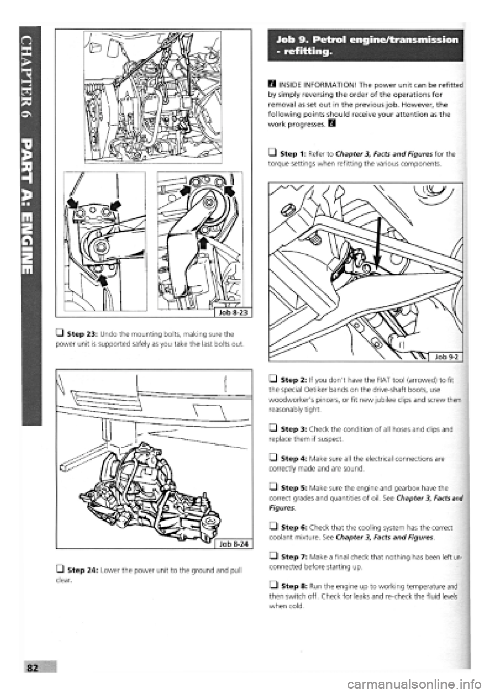
Q Step 23: Undo the mounting bolts, making sure the
power unit is supported safely as you take the last bolts out.
• Step 24: Lower the power unit to the ground and pull
clear.
Job 9. Petrol engine/transmission
- refitting.
Q INSIDE INFORMATION! The power unit can be refitted
by simply reversing the order of the operations for
removal as set out in the previous job. However, the
following points should receive your attention as the
work progresses. H
• Step 1: Refer to Chapter
3,
Facts and Figures for the
torque settings when refitting the various components.
• Step 2: If you don't have the FIAT too! (arrowed) to fit
the special Oetiker bands on the drive-shaft boots, use
woodworker's pincers, or fit new jubilee clips and screw them
reasonably tight.
• Step 3: Check the condition of all hoses and clips and
replace them if suspect.
• Step 4: Make sure all the electrical connections are
correctly made and are sound.
Q Step 5: Make sure the engine and gearbox have the
correct grades and quantities of oil. See Chapter
3,
Facts
and
Figures.
Q Step 6: Check that the cooling system has the correct
coolant mixture. See Chapter
3,
Facts and Figures.
• Step 7: Make a final check that nothing has been left un-
connected before starting up.
• Step 8: Run the engine up to working temperature and
then switch off. Check for leaks and re-check the fluid levels
when cold.
Page 84 of 171
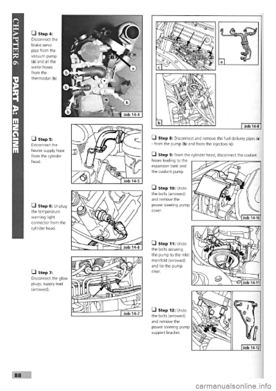
• Step 4:
Disconnect the
brake servo
pipe from the
vacuum pump
(a) and all the
water hoses
from the
thermostat (b).
• Step 5:
Disconnect the
heater supply hose
from the cylinder
head.
• Step 6: Unplug
the temperature
warning light
connector from the
cylinder head.
• Step 7:
Disconnect the glow
plugs, supply lead
(arrowed).
Q Step 8: Disconnect and remove the fuel delivery pipes (a)
- from the pump (b) and from the injectors (c).
• Step 9: From the
hoses leading to the
expansion tank and
the coolant pump.
• Step 10: Undo
the bolts (arrowed)
and remove the
power steering pump
cover.
• Step 11: Undo
the bolts securing
the pump to the inlet
manifold (arrowed)
and tie the pump
clear.
• Step 12: Undo
the bolts (arrowed)
and remove the
power steering pump
support bracket.
88
cylinder head, disconnect the coolant
Job 14-10
Job 14-12
Job 14-11
Page 86 of 171
are very clean, and great care is taken, it is possible to take an
average protrusion measurement based on measuring the
protrusion at each side (A) and (B) of the piston crown, using
a steel straight-edge and feeler gauges. Use the HIGHEST
average measurement of the four pistons as your working
figure.
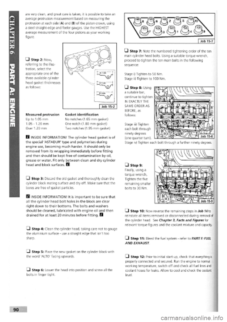
Q Step 2: Now,
referring to the illus-
tration, select the
appropriate one of the
three available cylinder
head gasket thicknesses
as follows:
Measured protrusion
Up to 1.05 mm
1.05
-
1.20 mm
Over 1.20 mm
B INSIDE INFORMATION! The cylinder head gasket is of
the special 'ASTADUR' type and polymerises during
engine use, becoming much harder. It should only be
removed from its wrapping immediately before fitting
and then should be kept free of contamination by oil,
grease or water. Fit only between clean and dry cylinder
head and block surfaces. B
• Step 3: Discard the old gasket and thoroughly clean the
cylinder block mating surface and dry off. Make sure that the
bores are free of gasket particles.
B INSIDE INFORMATION! It is important to be sure that
all the cylinder head bolt holes in the block are clear
right down to their bottoms. The bolts and washers
should be cleaned, lubricated with engine oil and then
drained for at least 20 minutes before fitting. B
• Step 4: Clean the cylinder head, taking care not to gouge
the aluminium surface
-
use a straight edge that isn't too
sharp.
Q Step 5: Place the new gasket on the cylinder block with
the word 'ALTO' facing upwards.
• Step 6: Lower the head into position and screw all the
bolts in finger tight.
LI Step 7: Note the numbered tightening order of the ten
main cylinder head bolts. Using a suitable torque wrench,
proceed to tighten the ten main bolts in the following
sequence:
Stage i) Tighten to 50 Nm.
Stage ii) Tighten to 100 Nm.
• Step 8: Using
a suitable bar,
continue to tighten
IN EXACTLY THE
SAME ORDER AS
BEFORE, as
follows:
• Step 9:
Finally, using a
torque wrench,
Tighten the five
remaining smaller
bolts to 30 Nm.
Q Step 10: Now reverse the remaining steps in Job
74
to
reinstate all items removed or disconnected during removal of
the cylinder head. See Chapter
3,
Facts and Figures for
relevant torque figures and the coolant mixture and capacity.
• Step 11: Bleed the fuel system
-
refer to PART
F: FUEL
AND EXHAUST
• Step 12: Prior to initial start up, check that everything is
properly connected and secured. Run the engine to normal
working temperature, switch off and check all fuel lines and
coolant hoses for leaks. Allow to cool and check the coolant
level.
Gasket identification
No notches (1.65 mm gasket)
One notch (1.80 mm gasket)
Two notches (1.95 mm gasket)
Stage iii) Tighten
each bolt through
ninety degrees
(one quarter turn).
Stage iv) Tighten each bolt through a further ninety degrees.
Page 91 of 171
Q Step 2: Before starting the engine, make sure all your
electrical connections are sound and your fuel, oil and coolant
connections are correct and secure.
Q Step 3: Run the engine to working temperature and then
allow to cool. Re-check all fluid levels.
Job 20. Diesel engine.
Mountings - replacement.
See
Job
12
and Job
18,
Step 20
Job 21. Diesel engine/
transmission (removed from car)
- separation.
Q Step 1: Remove the starter motor.
• Step 2: On the turbo version, undo the flange bolts see
Job
18,
Step 16A and withdraw the drive-shaft extension, if
still
fitted.
Q Step 3: Unbolt and remove the rear engine plate and the
gearbox, being careful to support the gearbox weight as it is
withdrawn.
Job 22. Diesel engine/
transmission (removed from car)
- reconnection.
Q Step 1: Before proceeding, check the condition of the
clutch and
its release mechanism. Make sure the driven plate
is
properly centred on the flywheel
-
see PART B: TRANS-
MISSION.
Q Step 2: Now reverse the order of separation, but be
careful when
engaging the gearbox input shaft with the
clutch
driven plate that you don't 'hang' its weight on the
splines.
Also,
see
Job 11.
Job 23. Diesel engine -
dismantling.
This Job should
be read in conjunction with Job 5 The
engines are
broadly similar although the information given in
this Job takes
priority for diesel engines. It is MOST
IMPORTANT that you read the FACT FILE on page 84.
SAFETY FIRST!
•
The inside
of diesel engines are particularly filthy
places!
•
Old diesel
oil
is
carcinogenic!
•
Wear suitable
impervious gloves!
I
• Step 1: Remove the timing belt and cylinder head. See
Jobs
13
and 14.
Q Step 2: Remove the alternator, water pump and
thermostat housing distribution pipe.
• Step 3: Remove the crankshaft timing belt sprocket.
Q INSIDE INFORMATION! Note that the bolt securing
the crankshaft sprocket has a left-hand thread and must
be undone clockwise. D
• Step 4: Unbolt the timing belt tensioner and idler pulleys.
• Step 5: Remove the injection pump sprocket.
Q INSIDE INFORMATION! You will need two FIAT tools
for this operation. One (No. 1860473000) is to prevent
the sprocket from turning when undoing the nut, and
the other (extractor No. 1842128000) to pull the sprocket
from the injection pump shaft. Alternatively it may be
possible to improvise a means of preventing sprocket
rotation, and a suitable three-leg puller may be carefully
used to withdraw the sprocket. Take care not to lose the
pump shaft Woodruff key. B
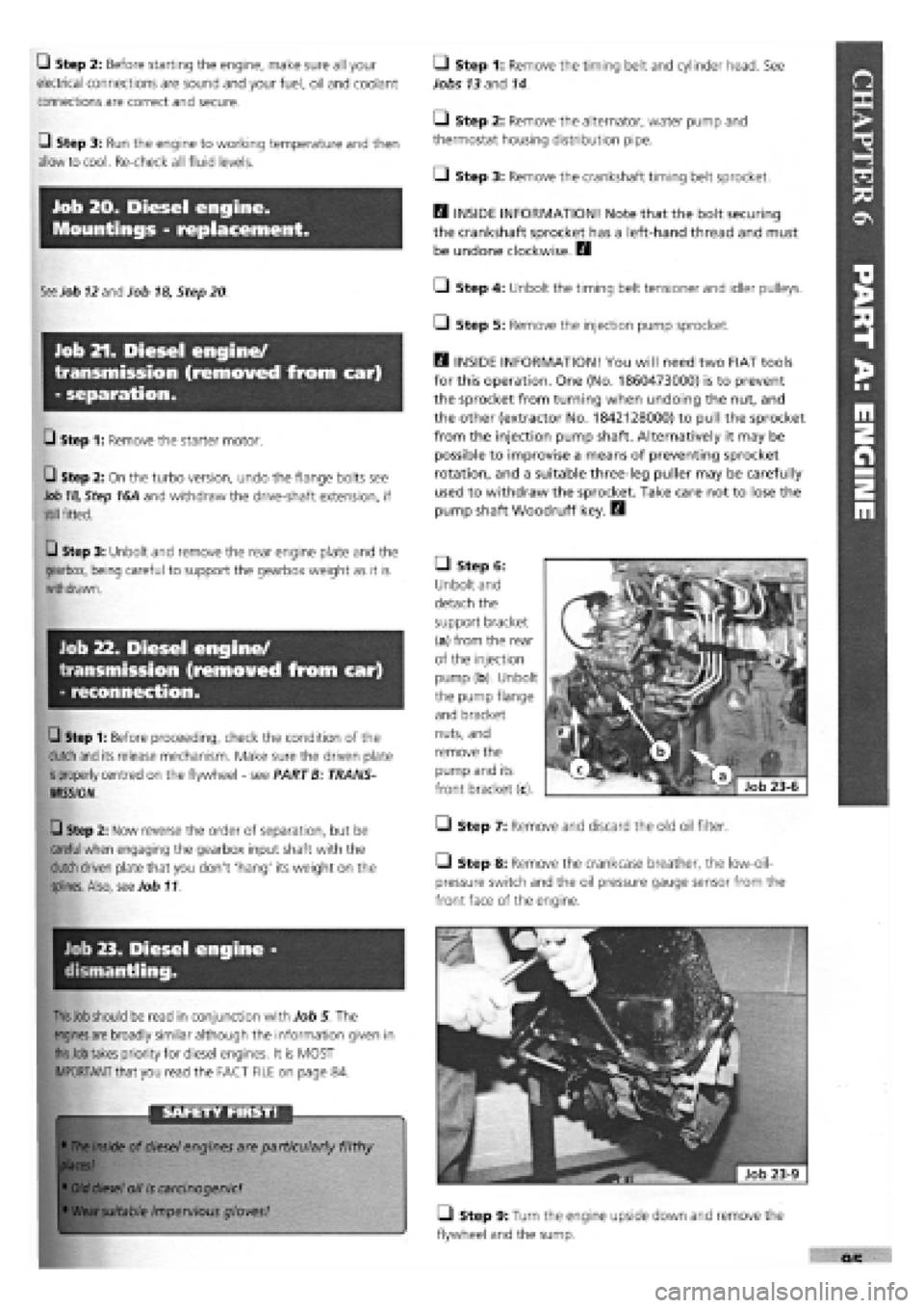
• Step 6:
Unbolt and
detach the
support bracket
(a) from the rear
of the injection
pump (b). Unbolt
the pump flange
and bracket
nuts, and
remove the
pump and its
front bracket (c).
• Step 7: Remove and discard the old oil filter.
Step 8: Remove the crankcase breather, the low-oil-
pressure switch and the oil pressure gauge sensor from the
front face of the engine.
• Step 9: Turn the engine upside down and remove the
flywheel and the sump.
Page 94 of 171
U Step 12: Fit a new seal to the front cover/oil pump
assembly, unless a new pump is being fitted, and install with a
new gasket, lightly oiling both gasket and seal. Align the cover
with the sump support plate.
PISTON CONNECTING RODS ASSEMBLIES
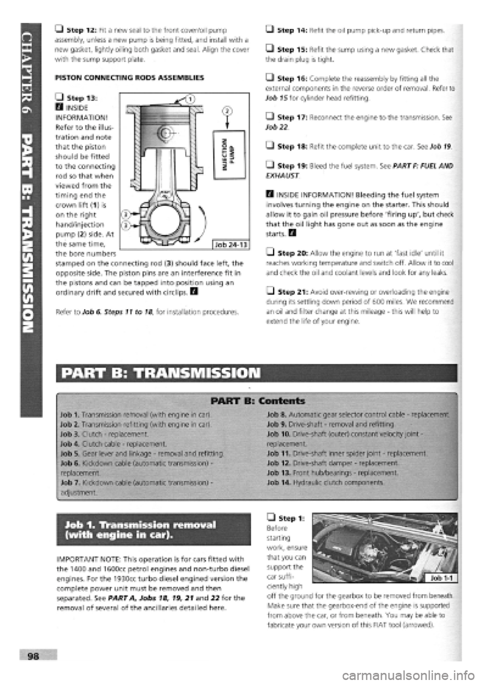
• Step 13:
H INSIDE
INFORMATION!
Refer to the illus-
tration and note
that the piston
should be fitted
to the connecting
rod so that when
viewed from the
timing end the
crown lift (1) is
on the right
hand/injection
pump (2) side. At
the same time,
the bore numbers
stamped on the connecting rod (3) should face left, the
opposite side. The piston pins are an interference fit in
the pistons and can be tapped into position using an
ordinary drift and secured with circlips. H
Refer to Job 6. Steps 11 to
18,
for installation procedures.
Q Step 14: Refit the oil pump pick-up and return pipes.
• Step 15: Refit the sump using a new gasket. Check that
the drain plug is tight.
• Step 16: Complete the reassembly by fitting all the
external components in the reverse order of removal. Refer to
Job
15
for cylinder head refitting.
• Step 17: Reconnect the engine to the transmission. See
Job
22
• Step 18: Refit the complete unit to the car. See Job
19
• Step 19: Bleed the fuel system. See PART F: FUEL AND
EXHAUST
Q INSIDE INFORMATION! Bleeding the fuel system
involves turning the engine on the starter. This should
allow it to gain oil pressure before 'firing up', but check
that the oil light has gone out as soon as the engine
starts. H
Q Step 20: Allow the engine to run at 'fast idle' until it
reaches working temperature and switch off. Allow it to cool
and check the oil and coolant levels and look for any leaks.
Q Step 21: Avoid over-rewing or overloading the engine
during its settling down period of 600 miles. We recommend
an oil and filter change at this mileage
-
this will help to
extend the life of your engine.
PART B: TRANSMISSION
PART B: Contents
Job 1. Transmission removal (with engine in car).
Job 2. Transmission refitting (with engine in car).
Job 3. Clutch
-
replacement.
Job 4. Clutch cable
-
replacement.
Job 5. Gear lever and linkage
-
removal and refitting.
Job 6. Kickdown cable (automatic transmission)
-
replacement.
Job 7. Kickdown cable (automatic transmission)
-
adjustment.
Job 8. Automatic gear selector control cable
-
replacement.
Job 9. Drive-shaft
-
removal and refitting.
Job 10. Drive-shaft (outer) constant velocity joint
-
replacement.
Job 11. Drive-shaft inner spider joint
-
replacement.
Job 12. Drive-shaft damper
-
replacement.
Job 13. Front hub/bearings
-
replacement.
Job 14. Hydraulic clutch components.
Job 1. Transmission removal
(with engine in car).
IMPORTANT NOTE: This operation is for cars fitted with
the 1400 and 1600cc petrol engines and non-turbo diesel
engines. For the 1930cc turbo diesel engined version the
complete power unit must be removed and then
separated. See PART A, Jobs 18, 19, 21 and 22 for the
removal of several of the ancillaries detailed here.
• Step 1:
Before
starting
work, ensure
that you can
support the
car suffi-
ciently high
off the ground for the gearbox to be removed from beneath.
Make sure that the gearbox-end of the engine is supported
from above the car, or from beneath. You may be able to
fabricate your own version of this FIAT tool (arrowed).
Page 103 of 171
Job 5. Coolant pump -
replacement.
L) Step 4: Lower the switch into water until the thread is
just
covered and the terminals remain dry.
G Step 5: Heat the water slowly. The bulb should light just
below boiling point (90 to 94 degrees Celsius) and go out
when
the temperature falls below 85 to 89 degrees Celsius.
G Step 6: Refit with a new O-ring but do not over tighten.
Job 4. Thermostat - replacement.
G Step 1: Drain the cooling system.
G Step 2: Disconnect the hoses from the thermostat
housing. Illustration Type 1, part 4 (petrol), or Type 2, part
6 (diesel). Undo the bolts and remove the housing/thermostat
assembly.
G Step 3: Clean the mating surfaces, fit the new unit with a
new
gasket.
G Step 4: Reconnect the hoses and refill the cooling system
with
the correct 50/50 FL 'Paraflu' anti-freeze mixture. See
Chapter
5, Servicing Your Car.
E9 INSIDE INFORMATION! For location of the water pump,
see illustration Type 1 (petrol), or Type 2 (diesel). B
• Step 1: Raise the bonnet and drain the cooling system.
Remove the air cleaner.
• Step 2: Unplug the alternator leads, slacken the bolts and
remove the drive belt. Remove the alternator.
• Step 3: Disconnect the hoses and the metal transfer pipe
from the pump.
• Step 4: Undo the securing bolts and remove the coolant
pump.
• Step 5: Discard the old gasket and clean off the mating
surfaces.
Q Step 6: Refit in reverse order using a new gasket.
• Step 7: Adjust the drivebelt tension. See Chapter 5,
Servicing Your Car.
• Step 8: Fill the cooling system with the correct 50/50
solution of FL 'Paraflu' anti-freeze solution. See Chapter 3,
Facts and Figures.
PART D: IGNITION SYSTEMS
——
PART D: Contents
Job 1. Ignition component positions. Job 4. Distributor
-
removal and refitting (1.6 litre engine).
Job
2.
Ignition coil
-
replacement. Job 5. Electronic ignition.
Job
3.
Distributor
-
removal and refitting (1.4 litre engine).
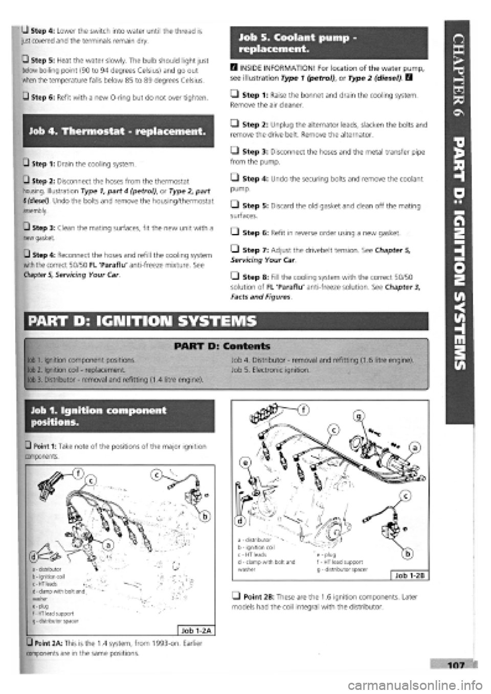
Job 1. Ignition component
positions.
washer g - distributor spacer Job 1-2B
G Point 1: Take note of the positions of the major ignition
components.
Q Point 2B: These are the 1.6 ignition components. Later
models had the coil integral with the distributor.
o
a
>
H
w
w
ON
(A
H
ri
S
VI
107
G Point 2A: This is the 1.4 system, from 1993-on. Earlier
components are in the same positions.
a
-
distributor b
-
ignition coil ^ c-HT leads ^ d
-
clamp with bolt and washer e
-
plug f
-
HT lead support g
-
distributor spacer
Job 1-2 A
Page 114 of 171
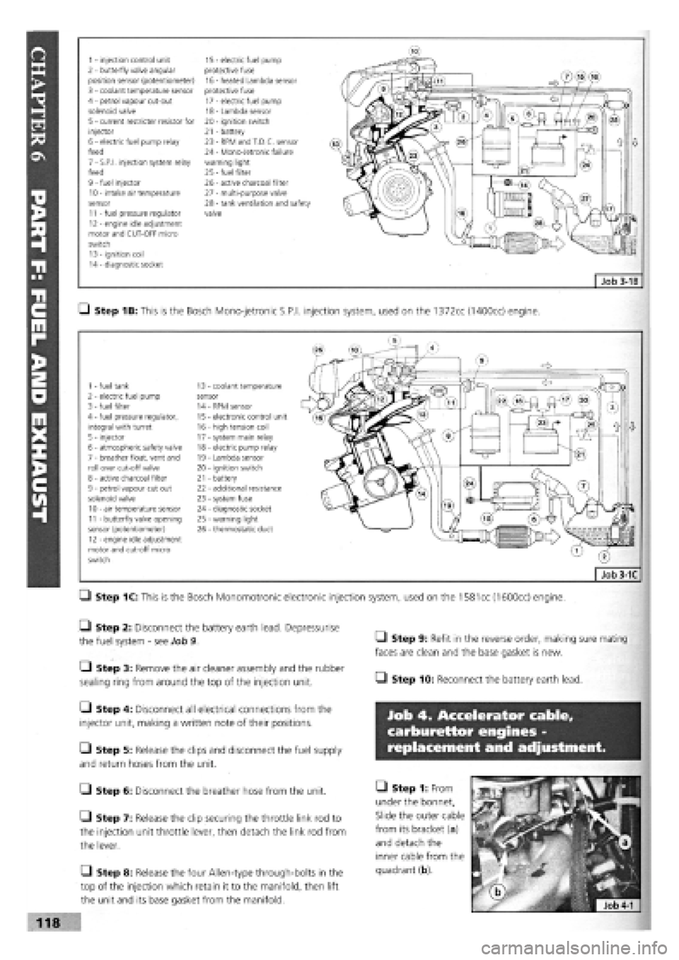
1 - injection control unit 15 - electric fuel pump 2 - butterfly valve angular protective fuse position sensor (potentiometer) 16 - heated Lambda sensor 3 - coolant temperature sensor protective fuse 4 - petrol vapour cut-out 17 - electric fuel pump solenoid valve 18 - Lambda sensor 5 - current restricter resistor for 20 - ignition switch injector 21 - battery 6 - electric fuel pump relay 23 - RPM and T.D.C. sensor feed 24 - Mono-Jetronic failure 7 - S.P.I, injection system relay warning light feed 25
-
fuel filter 9 - fuel injector 26 - active charcoal filter 10 - intake air temperature 27 - multi-purpose valve sensor 28 - tank ventilation and safety 11 - fuel pressure regulator valve 12 - engine idle adjustment motor and CUT-OFF micro switch 13 - ignition coil 14 - diagnostic socket
Q Step 1B: This is the Bosch Mono-jetronic S.P.I, injection system, used on the 1372cc (1400cc) engine.
1 - fuel tank 13 coolant temperature 2 - electric fuel pump sensor 3 - fuel filter 14 RPM sensor 4 - fuel pressure regulator, 15 electronic control unit integral with turret 16 - high tension coil 5 - injector 17 - system main relay 6 - atmospheric safety valve 18 - electric pump relay 7 - breather float, vent and 19 - Lambda sensor roll over cut-off valve 20 - ignition switch 8 - active charcoal filter 21 - battery 9 - petrol vapour cut out 22 - additional resistance solenoid valve 23 - system fuse 10 - air temperature sensor 24 - diagnostic socket 11 - butterfly valve opening 25 - warning light sensor (potentiometer) 26 - thermostatic duct 12 - engine idle adjustment motor and cut-off micro switch
Q Step 1C: This is the Bosch Monomotronic electronic injection system, used on the
1581
cc (1600cc) engine.
• Step 2: Disconnect the battery earth lead. Depressurise
the fuel system
-
see Job 9.
• Step 3: Remove the air cleaner assembly and the rubber
sealing ring from around the top of the injection unit.
Q Step 4: Disconnect all electrical connections from the
injector unit, making a written note of their positions.
Q Step 5: Release the clips and disconnect the fuel supply
and return hoses from the unit.
G Step 6: Disconnect the breather hose from the unit.
• Step 7: Release the clip securing the throttle link rod to
the injection unit throttle lever, then detach the link rod from
the lever.
Q Step 8: Release the four Allen-type through-bolts in the
top of the injection which retain it to the manifold, then lift
the unit and its base gasket from the manifold.
• Step 9: Refit in the reverse order, making sure mating
faces are clean and the base gasket is new.
• Step 10: Reconnect the battery earth lead.
Job 4. Accelerator cable,
carburettor engines -
replacement and adjustment.
• Step 1: From
under the bonnet,
Slide the outer cable
from its bracket (a)
and detach the
inner cable from the
quadrant (b).
118