dead battery FIAT TEMPRA 1988 Service And Repair Manual
[x] Cancel search | Manufacturer: FIAT, Model Year: 1988, Model line: TEMPRA, Model: FIAT TEMPRA 1988Pages: 171, PDF Size: 18.05 MB
Page 44 of 171
• Job 25. Check ignition timing.
_ FACT FILE: IGNITION SYSTEM TYPES
Two different types of electronic ignition
systems have been fitted to the petrol
engines covered by this manual.
The earlier Breakerless Inductive Discharge System can
be adjusted. Its distributor is fitted as shown in illus-
tration 25A.
The later, Digiplex 2 system, has an integrated ignition
and fuel injection control system and any checks and
adjustments will need to be carried out by your FIAT
dealership with the appropriate diagnostic equipment.
See Job 28.
MAGNETI MARELLI BREAKERLESS INDUCTIVE
DISCHARGE IGNITION SYSTEM
CHECK VACUUM AND MECHANICAL ADVANCE SYSTEMS
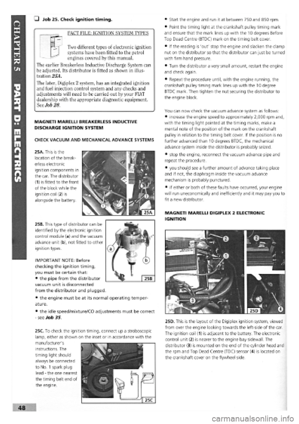
25A. This is the
location of the break-
erless electronic
ignition components in
the car. The distributor
(1) is fitted to the front
of the block while the
ignition coil
(2)
is
alongside the battery.
25B. This type of distributor can be
identified by the electronic ignition
control module (a) and the vacuum
advance unit (b), not fitted to other
ignition types.
• the engine must be at
ature.
• the idle speed/mixture/CO adjustments must be correct
-
see Job 35.
• Start the engine and run it at between 750 and 850 rpm.
• Point the timing light at the crankshaft pulley timing mark
and ensure that the mark lines up with the 10 degrees Before
Top Dead Centre (BTDC) mark on the timing belt cover.
• If the reading is 'out' stop the engine and slacken the clamp
nut on the distributor so that the distributor can just be turned
with firm hand pressure.
• Turn the distributor a very small amount, restart the engine
and check again.
• Repeat the procedure until, with the engine running, the
crankshaft pulley timing mark lines up with the 10 degree
BTDC mark. Then tighten the nut securing the distributor to
the engine block.
You can now check the vacuum advance system as follows:
• increase the engine speed to approximately 2,000 rpm and,
with the timing light pointed at the timing marks, make a
mental note of the position of the mark on the crankshaft
pulley in relation to the timing belt cover. If the position is no
further advanced than 10 degrees BTDC, the mechanical
advance system inside the distributor is probably seized.
• stop the engine, reconnect the vacuum advance pipe and
repeat the procedure.
• you should see a further amount of advance taking place
and if not, the diaphragm inside the vacuum advance
mechanism is probably punctured.
• if either or both of these faults have occurred, your engine
will run uneconomical^ and inefficiently and it may pay you to
fit a new distributor.
MAGNETI MARELLI DIGIPLEX 2 ELECTRONIC
IGNITION
25D. This is the layout of the Digiplex ignition system, viewed
from over the engine looking towards the left-side of the car.
The ignition coil (1) is adjacent to the battery. The electronic
control unit (2) is nearer to the engine bay sidewall. The
distributor (3) is mounted on the end of the cylinder head and
the rpm and Top Dead Centre (TDC) sensor (4) is located on
the crankshaft cover on the flywheel side.
IMPORTANT NOTE: Before
checking the ignition timing,
you must be certain that:
• the pipe from the distributor
vacuum unit is disconnected
from the distributor and plugged.
its normal operating temper-
instructions. The
timing light should
always be connected
to No.
1
spark plug
lead
-
the one nearest
the timing belt end of
the engine.
48
25C. To check the ignition timing, connect up a stroboscopic
lamp, either as shown on the inset or in accordance with the
manufacturer's
Page 105 of 171
SAFETY FIRST!
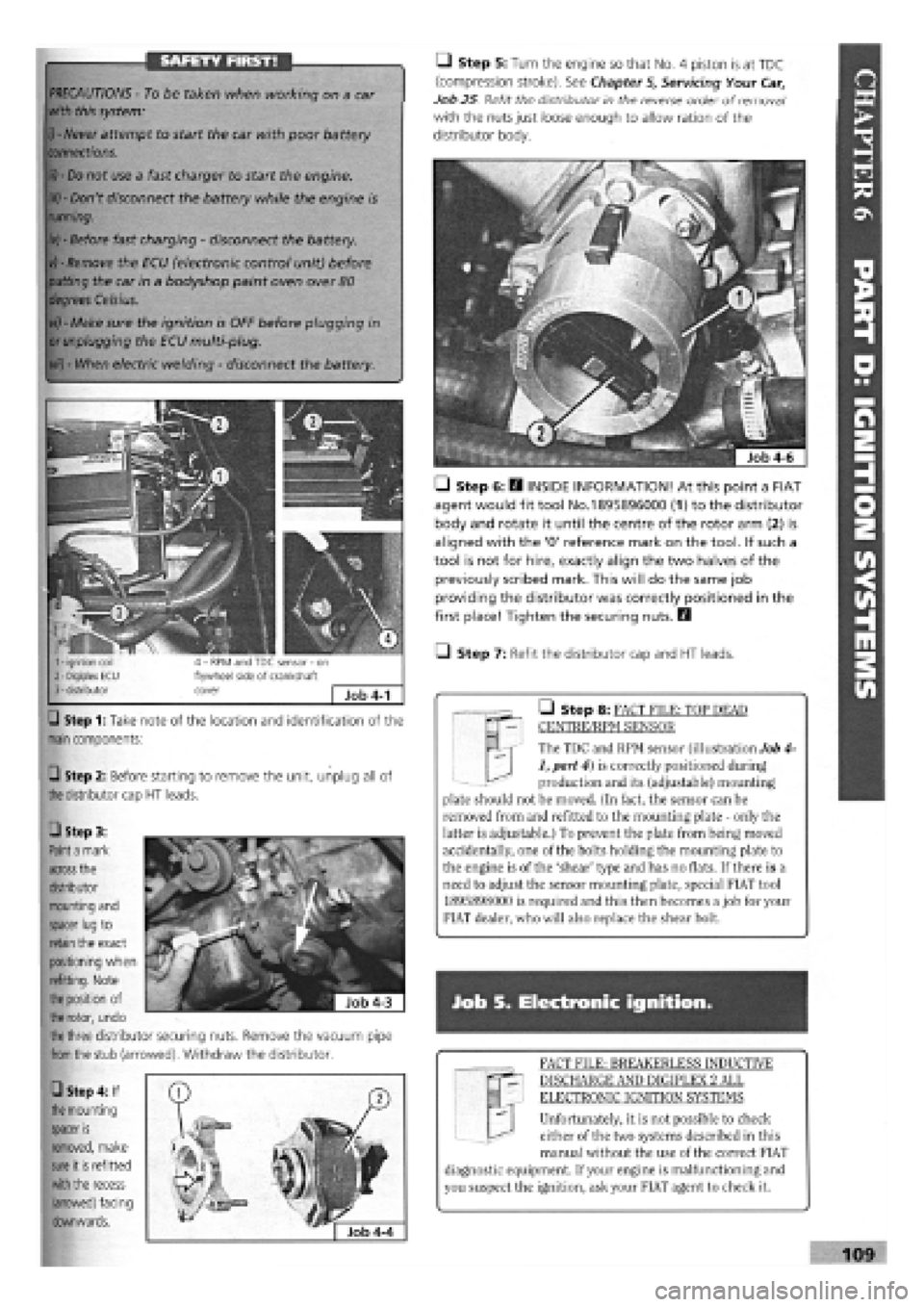
Step 1: Take note of the location and identification of the
main
components:
Q Step 2: Before starting to remove the unit, unplug all of
the
distributor cap
HT
leads.
M | The TDC and RPM sensor (illustration Job 4-
1, part 4) is correctly positioned during
production and its (adjustable) mounting
plate should not be moved. (In fact, the sensor can be
removed from and refitted to the mounting plate - only the
latter is adjustable.) To prevent the plate from being moved
accidentally, one of the bolts holding the mounting plate to
the engine is of the 'shear' type and has no flats. If there is a
need to adjust the sensor mounting plate, special FIAT tool
1895898000 is required and this then becomes a job for your
FIAT dealer, who will also replace the shear bolt.
• Step 8: FACT FILE: TOP DEAD
CENTRE/RPM SENSOR
PRECAUTIONS -
To be taken when working on a car
with this system:
i) - Never
attempt to start the car with poor battery
connections.
ii) - Do
not use a fast charger to start the engine.
iii) -
Don't disconnect the battery while the engine is
running.
iv) -
Before fast charging
-
disconnect the battery.
vj - Remove
the ECU (electronic control unit) before
putting
the car in a bodyshop paint oven over
80
degrees Celsius.
vi) -
Make sure the ignition is OFF before plugging in
or unplugging
the ECU multi-plug.
vii) -
When electric welding
-
disconnect the battery.
Q Step 5: Turn the engine so that No. 4 piston is at TDC
(compression stroke). See Chapter
5,
Servicing Your Car,
Job 25 Refit the distributor in the reverse order of removal1
with the nuts just loose enough to allow ration of the
distributor body.
• Step 6: E3 INSIDE INFORMATION! At this point a FIAT
agent would fit tool No.1895896000 (1) to the distributor
body and rotate it until the centre of the rotor arm (2) is
aligned with the '0' reference mark on the tool. If such a
tool is not for hire, exactly align the two halves of the
previously scribed mark. This will do the same job
providing the distributor was correctly positioned in the
first place! Tighten the securing nuts. Q
• Step 7: Refit the distributor cap and HT leads.
Job S. Electronic ignition.
FACT FILE: BREAKERLESS INDUCTIVE
DISCHARGE AND DIGIPLEX 2 ALL
ELECTRONIC IGNITION SYSTEMS
Unfortunately, it is not possible to check
either of the two systems described in this
manual without the use of the correct FIAT
diagnostic equipment. If your engine is malfunctioning and
you suspect the ignition, ask your FIAT agent to check it.
109
• Step 3:
Paint a
mark
across
the
distributor
mounting and
spacer lug
to
retain
the exact
positioning when
refitting. Note
the position
of
the rotor,
undo
the three
distributor securing nuts. Remove the vacuum pipe
from the
stub (arrowed). Withdraw the distributor.
• Step 4: If
the
mounting
spacer
is
removed, make
sure
it
is
refitted
with the
recess
(arrowed) facing
downwards.