fuel pressure FIAT TEMPRA 1988 Service And Repair Manual
[x] Cancel search | Manufacturer: FIAT, Model Year: 1988, Model line: TEMPRA, Model: FIAT TEMPRA 1988Pages: 171, PDF Size: 18.05 MB
Page 2 of 171
Running The Vehicle
NEVER start the engine unless the gearbox is in neutral (or
'Park' in the case of automatic transmission) and the hand
brake is fully applied.
NEVER run catalytic converter equipped vehicles without the
exhaust system heat shields in place.
TAKE CARE when parking vehicles fitted with catalytic
converters. The 'cat' reaches extremely high temperatures and
any combustible materials under the car, such as long dry
grass, could be ignited.
Personal Safety
NEVER siphon fuel, antifreeze, brake fluid or other such toxic
liquids by mouth, or allow contact with your skin. Use a
suitable hand pump and wear gloves.
BEFORE undertaking dirty jobs, use a barrier cream on your
hands as a protection against infection. Preferably, wear
suitable gloves, available from DIY outlets.
WEAR IMPERVIOUS GLOVES for sure when there is a risk of
used engine oil coming into contact with your skin. It can
cause cancer.
WIPE UP any spilt oil, grease or water off the floor
immediately.
MAKE SURE that spanners and all other tools are the right size
for the job and are not likely to slip. Never try to 'double-up'
spanners to gain more leverage.
SEEK HELP if you need to lift something heavy which may be
beyond your capability. Don't forget that when lifting a heavy
weight, you should keep your back straight and bend your
knees to avoid injuring your back.
NEVER take risky short-cuts or rush to finish a job. Plan ahead
and allow plenty of time.
BE METICULOUS and keep the work area tidy
-
you'll avoid
frustration, work better and lose less.
KEEP children and animals right-away from the work area and
from unattended vehicles.
ALWAYS tell someone what you're doing and have them
regularly check that all is well, especially when working alone
on, or under, the vehicle.
Fire!
Petrol (gasoline) is a dangerous and highly flammable liquid
requiring special precautions. When working on the fuel
system, disconnect the vehicle battery earth (ground) terminal
whenever possible and always work outside, or in a very well
ventilated area. Any form of spark, such as that caused by an
electrical fault, by two metal surfaces striking against each
other, by a central heating boiler in the garage 'firing up', or
even by static electricity built up in your clothing can, in a
confined space, ignite petrol vapour causing an explosion.
Take great care not to spill petrol on to the engine or exhaust
system, never allow any naked flame anywhere near the work
area and, above all, don't smoke.
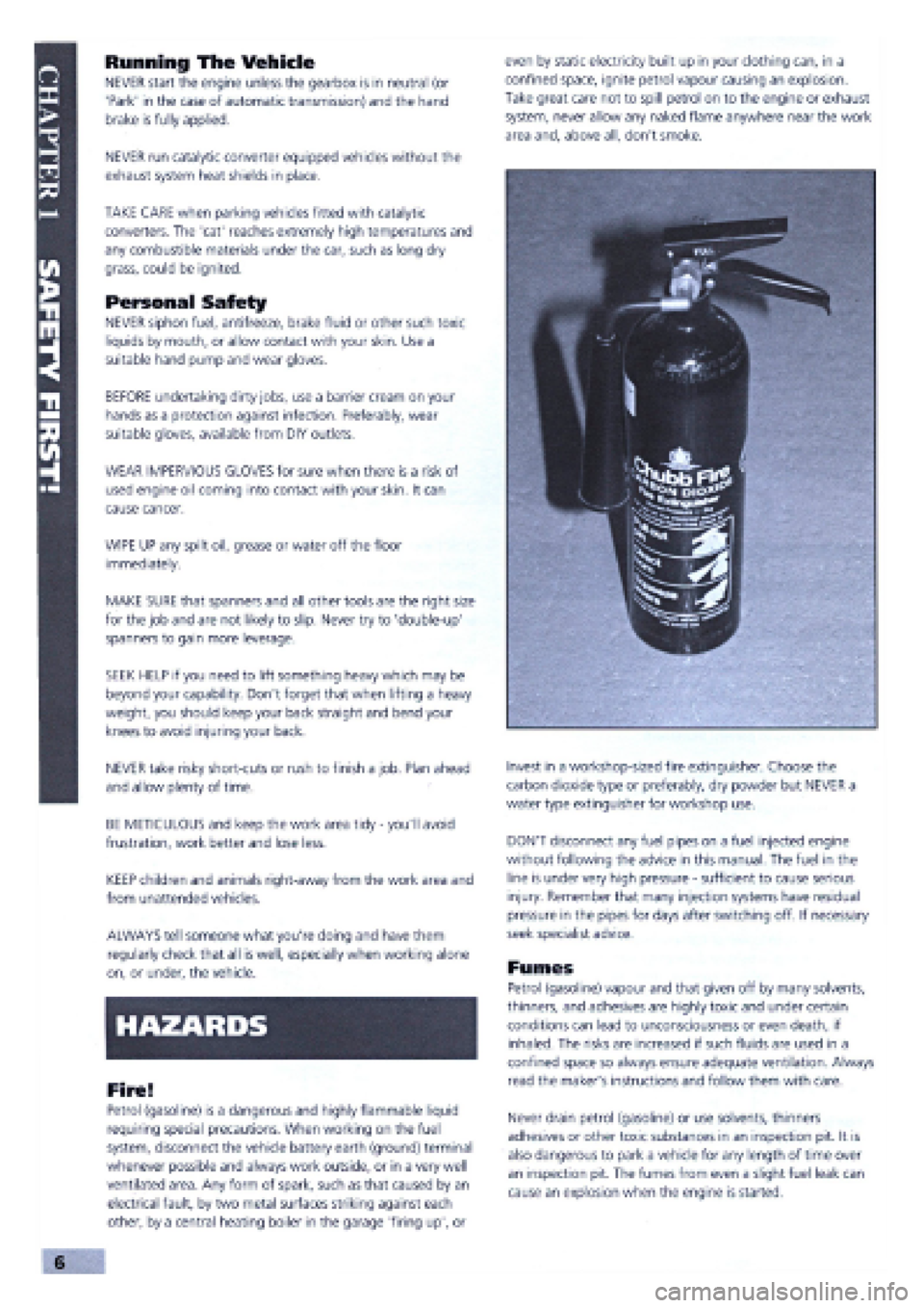
Invest in a workshop-sized fire extinguisher. Choose the
carbon dioxide type or preferably, dry powder but NEVER a
water type extinguisher for workshop use.
DON'T disconnect any fuel pipes on a fuel injected engine
without following the advice in this manual. The fuel in the
line is under very high pressure
-
sufficient to cause serious
injury. Remember that many injection systems have residual
pressure in the pipes for days after switching off. If necessary
seek specialist advice.
Fumes
Petrol (gasoline) vapour and that given off by many solvents,
thinners, and adhesives are highly toxic and under certain
conditions can lead to unconsciousness or even death, if
inhaled. The risks are increased if such fluids are used in a
confined space so always ensure adequate ventilation. Always
read the maker's instructions and follow them with care.
Never drain petrol (gasoline) or use solvents, thinners
adhesives or other toxic substances in an inspection pit. It is
also dangerous to park a vehicle for any length of time over
an inspection pit. The fumes from even a slight fuel leak can
cause an explosion when the engine is started.
v ,,, Oil;::;s
Page 6 of 171
• Repeat this operation three more times until the
complete code number has been entered, if the code
has been entered in correctly LED B will start flashing.
• Release button A (see illustration
1B).
Red LED B
flashes for 8 seconds indicating the new remote unit's
code has been stored.
IMPORTANT NOTE: If the LED does not illuminate
when remote unit button (illustration 1B, button
O is pressed, change the remote unit's battery.
• Insert the emergency key A into the emergency switch
slot in the glove compartment turn the key to the left to
switch the alarm off (see inset).
• Turn the key back towards its original position to
switch the alarm system back on.
IMPORTANT NOTE: As the alarm system absorbs
energy, if you are not planning on using the car
for a long period of time, turn the alarm exclusion
key to the off position, so as not to run the vehicle
battery down.
• 2. IGNITION SWITCH AND
STEERING COLUMN LOCK
IGNITION SWITCH
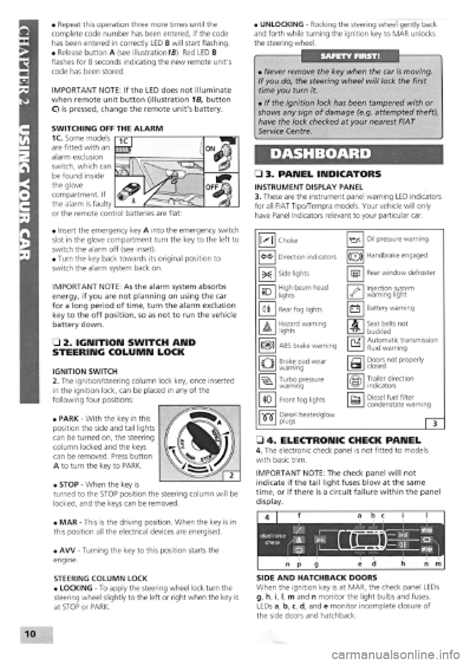
2. The ignition/steering column lock key, once inserted
in the ignition lock, can be placed in any of the
following four positions:
• PARK
-
With the key in this
position the side and tail lights
can be turned on, the steering
column locked and the keys
can be removed. Press button
A to turn the key to PARK.
• STOP
-
When the key is
turned to the STOP position the steering column will be
locked, and the keys can be removed.
• MAR
-
This is the driving position. When the key is in
this position all the electrical devices are energised.
• AW
-
Turning the key to this position starts the
engine.
STEERING COLUMN LOCK
• LOCKING
-
To apply the steering wheel lock turn the
steering wheel slightly to the left or right when the key is
at STOP or PARK.
• UNLOCKING
-
Rocking the steering wheel gently back
and forth while turning the ignition key to MAR unlocks
the steering wheel.
• 3. PANEL INDICATORS
INSTRUMENT DISPLAY PANEL
3. These are the instrument panel warning LED indicators
for all FIAT Tipo/Tempra models. Your vehicle will only
have Panel Indicators relevant to your particular car.
• 4. ELECTRONIC CHECK PANEL
4. The electronic check panel is not fitted to models
with basic trim.
IMPORTANT NOTE: The check panel will not
indicate if the tail light fuses blow at the same
time, or if there is a circuit failure within the panel
display.
SIDE AND HATCHBACK DOORS
When the ignition key is at MAR, the check panel LEDs
g, h, i, I, m and n monitor the light bulbs and fuses.
LEDs a, b, c, d, and e monitor incomplete closure of
the side doors and hatchback.
• Never remove the key when the car is moving.
If you do, the steering wheel will lock the first
time you turn it.
• If the ignition lock has been tampered with or
shows any sign of damage (e.g. attempted theft),
have the lock checked at your nearest FIAT
Service Centre.
M Choke Oil pressure warning
Direction indicators (®) Handbrake engaged
-X: Side lights m Rear window defroster
10 High beam head
lights '•y Injection system warning light
<1* Rear fog lights • Battery warning
A Hazard warning lights A Seat belts not
buckled
m ABS brake warning a Automatic transmission fluid warning
o Brake pad wear warning a Doors not properly closed
Turbo pressure warning Trailer direction indicators
10 Front fog lights a Diesel fuel filter condenstate warning
•515" Diesel heater/glow •515" plugs 3
SWITCHING OFF THE ALARM
1C. Some models
are fitted with an
alarm exclusion
switch, which can
be found inside
the glove
compartment. If
the alarm is faulty
or the remote control batteries are flat:
Page 14 of 171
October 1991 2.0 i.e. 16v introduced, with 1995cc, 16 valve
high-performance DOHC engine, catalytic converter, sports
suspension, front and rear disc brakes. ABS available as
option.
January 1992 Existing Tipo models lightly facelifted and
redesignated 1.4 Formula, 1.45, 1.6S, 1.6SX, 1.9TD SX,
1.8 i.e. SX. 1.7D discontinued. SX versions with digital
instruments.
Tempra 1.9 TDS (turbo diesel) Station Wagon introduced. 1.4
and 1.9D saloons discontinued.
May 1992 Tempra 1.8 i.e. SX Saloon and Station Wagon
discontinued.
June 1992 Tempra 2.0 i.e. SX saloon and station wagon
models introduced, with high performance 1995cc DOHC fuel
injected engine, catalytic converter and disc brakes front and
rear.
Tipo 1.4 and all Tipo and Tempra 1.6 models (except Selecta)
now with a catalytic converter and fuel injection in place of
Weber twin-choke carburettor. Designated i.e. in badging.
December 1992 Tipo 1.8 i.e. and 1.6 Selecta discontinued.
February 1993 Tipo 2.0 i.e. GT introduced. Slightly lower
performance and spec, version of the 16v model.
July 1993 Tipo 1.4 now available as a 3-door or 5-door
hatchback. 2.0 i.e. 16v now only available as 3-door. Tipo 2.0
i.e. GT replaced by similar spec. 2.0 i.e. SLX.
Tempra 2.0 i.e. SX saloons and estates now only available
with auto, gearbox. Otherwise, SX models become known as
SLX, with colour-coded mirrors and ABS brakes. Most Tempras
now with body-coloured bumpers. 1.9D (non turbo Diesel re-
introduced).
All Tipo and Tempra models now with revised front-end
styling
-
narrower headlights and revised grille. Improved crash
protection, including side impact beams, safety steering wheel
and uprated brakes. Power steering, central locking, electric
windows all standard.
February 1994 Tipo 1.7 non-turbo diesel re-introduced as
1.7 DS.
May 1994 Tempra 1.9DS Station Wagon introduced.
September 1994 Most models available with driver's airbag,
fire prevention system and seat belt pre-tensioners.
December 1994 Tempra 1.6 i.e. versions get M.P.I, engine.
February/March 1995 All models with VIN number window
etching and immobiliser standard on all Tempra petrol models.
October 1995 Immobiliser fitted to Tempra D and TD models.
End of 1995 Tipo discontinued.
Mid-1996 Tempra discontinued.
PART B: VITAL STATISTICS
All Tipo models
-
55 litres, except petrol with catalytic converter
- 51
litres.
All Tempra models
-
65 litres, except petrol with catalytic converter
-
62 litres.
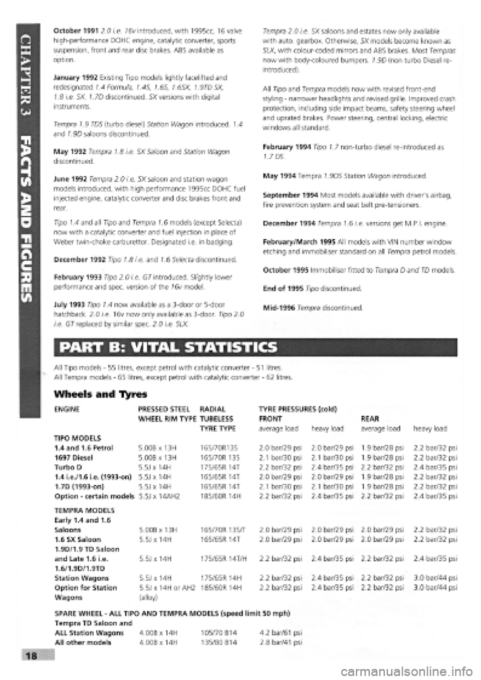
Wheels and Tyres
ENGINE PRESSED STEEL RADIAL TYRE PRESSURES (cold)
WHEEL RIM TYPE TUBELESS FRONT REAR
TYRE TYPE average load heavy load average load heavy load
TIPO MODELS
1.4 and 1.6 Petrol 5.00B x 13H 165/70R13S 2.0 bar/29 psi 2.0 bar/29 psi 1.9 bar/28 psi 2.2 bar/32 psi
1697 Diesel 5.00B x 13H 165/70R 13S 2.1 bar/30 psi 2.1 bar/30 psi 1.9 bar/28 psi 2.2 bar/32 psi
Turbo D 5.5J x 14H
175/65 R
14T 2.2 bar/32 psi 2.4 bar/35 psi 2.2 bar/32 psi 2.4 bar/35 psi
1.4 i.e./1.6 i.e. (1993-on) 5.5J x 14H
165/65 R
14T 2.0 bar/29 psi 2.0 bar/29 psi 1.9 bar/28 psi 2.2 bar/32 psi
1.7D (1993-on) 5.5J x 14H 165/65R 14T 2.1 bar/30 psi 2.1 bar/30 psi 1.9 bar/28 psi 2.2 bar/32 psi
Option
-
certain models 5.5J x 14AH2 185/60R 14H 2.2 bar/32 psi 2.4 bar/35 psi 2.2 bar/32 psi 2.4 bar/35 psi
TEMPRA MODELS
Early 1.4 and 1.6
Saloons 5.00B x 13H 165/70R 13S/T 2.0 bar/29 psi 2.0 bar/29 psi 2.0 bar/29 psi 2.2 bar/32 psi
1.6 SX Saloon 5.5J x 14H 165/65R 14T 2.0 bar/29 psi 2.0 bar/29 psi 2.0 bar/29 psi 2.2 bar/32 psi
1.9D/1.9 TD Saloon
and Late 1.6 i.e. 5.5J x 14H 175/65R 14T/H 2.2 bar/32 psi 2.4 bar/35 psi 2.2 bar/32 psi 2.4 bar/35 psi
1.6/1.9D/1.9TD
Station Wagons 5.5J x 14H 175/65R 14H 2.2 bar/32 psi 2.4 bar/35 psi 2.2 bar/32 psi 3.0 bar/44 psi
Option for Station 5.5J x 14H or AH2 185/60 R 14H 2.2 bar/32 psi 2.4 bar/35 psi 2.2 bar/32 psi 3.0 bar/44 psi
Wagons (alloy)
SPARE WHEEL
-
ALL TIPO AND TEMPRA MODELS (speed limit 50 mph)
Tempra TD Saloon and
ALL Station Wagons 4.00B x 14H 105/70 B14 4.2
bar/61
psi
All other models 4.00Bx14H 135/80 B14 2.8
bar/41
psi
Page 19 of 171
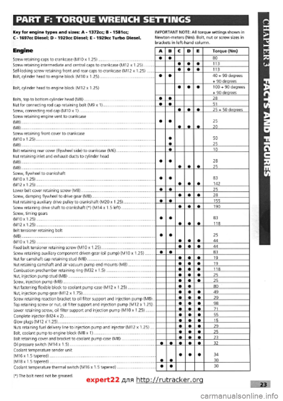
PART F: TORQUE WRENCH SETTINGS
Key for engine types and sizes: A
-
1372cc; B
-
1581cc;
C
-
1697cc Diesel; D
-
1929cc Diesel; E
-
1929cc Turbo Diesel.
Engine
Screw retaining caps to crankcase (M10 x 1.25)
Screw retaining intermediate and central caps to crankcase (M12 x 1.25)...
Self-locking screw retaining front and rear caps to crankcase (M12 x 1.25)
Bolt, cylinder head to engine block (M10 x 1.25)
IMPORTANT NOTE: All torque settings shown in
Newton-meters (Nm). Bolt, nut or screw sizes in
brackets in left-hand column.
Bolt, cylinder head to engine block (M12 x 1.25)
Bolts, top to bottom cylinder head (M8)
Nut for connecting rod cap retaining bolt (M9 x 1)
Screw, connecting rod cap (M10 x 1)
Screw retaining engine vent to crankcase
(M8)
(M8)
Screw retaining front cover to crankcase
(MlOx 1.25)
(M8)
Bolt retaining rear cover (flywheel side) to crankcase (M6)
Nut retaining inlet and exhaust ducts to cylinder head
(M8)
(M8)
Screw, flywheel to crankshaft
(M10x 1.25)
(M12
x
1.25)
Lower belt cover retaining screw (M8)
Screw, damping flywheel to drive gear (M8)
Nut retaining auxiliary drive pulley to crankshaft (M20 x 1.25)
Screw retaining drive shaft to crankshaft (*) (M14 x 1.5 left)
Screw, timing gears
(M10x 1.25)
(M12x 1.25)
Belt tensioner retaining bolt
(M8)
(M10x 1.25)
Fixed belt tensioner retaining screw (M10 x 1.25)
Screw retaining auxiliary component driven gear (oil pump) (M10 x 1.25)
Nut for camshaft cap retaining stud (M8)
Nut retaining camshaft and air vacuum pump end mounts (M8)
Combustion prechamber retaining ring (M32 x 1.5)
Nut, injection pump stud (M8)
Screw, injection pump (M8)
Nut fastening flexible block to coolant pump case (M12 x 1.25)
Nut, injection pump gear (M12 x 1.75)
Screw retaining reaction bracket to oil filter support and injection pump (M8).
Top retaining screw or nut, oil filter support and injection pump (M12 x 1.25)
Lower retaining screw, oil filter support and injection pump (M10 x 1.25)
Complete injector (M24 x 2)
Glow plugs (M12 x 1.25)
Nuts retaining fuel delivery line to injection pump and injector (M12 x 1.25)...
Bolt, coolant pump to engine block (M8 x 1)
Bolt retaining cover and bracket to coolant pump case (M8)
Oil pressure switch (M14 x 1.5)
Coolant temperature sender unit
(M16 x 1.5 tapered)
(M18x 1.5 tapered)
Coolant temperature thermal switch (M16 x 1.5 tapered)
(*) The bolt need not be greased.
A B C D E Torque (Nm)
• • 80
• • • 113
• • • 113
• • 40
+
90 degrees
+ 90 deqrees
• • • 100
+
90 degrees
+ 90 deqrees
• • 28
• • 51
• • • 25 + 50 deqrees
• •
• • •
25
20
• • 50
25
• 10
• •
• • •
28
25
• •
• • •
83
142
• • 25
• • • 28
• • 155
• • • 190
• •
• • •
83
118
• •
• • •
25
44
• • • 44
• • 83
• • • 19
• • • 19
• • • 118
• • • 25
• • • 25
• • 80
• • • 49
• • • 29
• • • 98
• • • 71
• • • 55
• • • 15
• • • 29
• • • 25
• • • 23
32
• •
• • • 34
30
• • 30
expert22 fl/i* http://rutracker.org 23
Page 20 of 171
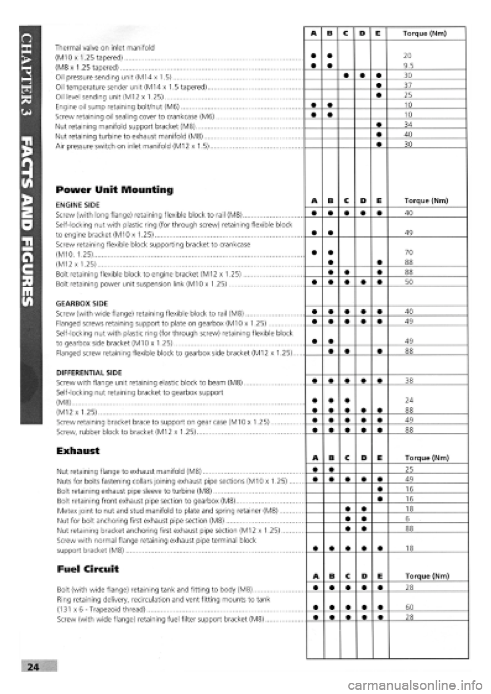
Thermal valve on inlet manifold
(M10 x 1.25 tapered)
(M8 x 1.25 tapered)
Oil pressure sending unit (M14 x 1.5)
Oil temperature sender unit (M14 x 1.5 tapered)....
Oil level sending unit (M12 x 1.25)
Engine oil sump retaining bolt/nut (M6)
Screw retaining oil sealing cover to crankcase (M6)
Nut retaining manifold support bracket (M8)
Nut retaining turbine to exhaust manifold (M8)
Air pressure switch on inlet manifold (M12 x 1.5)...
Power Unit Mounting
ENGINE SIDE
Screw (with long flange) retaining flexible block to rail (M8)
Self-locking nut with plastic ring (for through screw) retaining flexible block
to engine bracket (M10 x 1.25)
Screw retaining flexible block supporting bracket to crankcase
(M10. 1.25)
(M12 x 1.25)
Bolt retaining flexible block to engine bracket (M12 x 1.25)
Bolt retaining power unit suspension link (M10 x 1.25)
GEARBOX SIDE
Screw (with wide flange) retaining flexible block to rail (M8)
Flanged screws retaining support to plate on gearbox (M10 x 1.25)
Self-locking nut with plastic ring (for through screw) retaining flexible block
to gearbox side bracket (M10 x 1.25)
Flanged screw retaining flexible block to gearbox side bracket (M12 x 1.25).
DIFFERENTIAL SIDE
Screw with flange unit retaining elastic block to beam (M8)
Self-locking nut retaining bracket to gearbox support
(M8)
(M12 x 1.25)
Screw retaining bracket brace to support on gear case (M10 x 1.25)
Screw, rubber block to bracket (M12 x 1.25)
Exhaust
Nut retaining flange to exhaust manifold (M8)
Nuts for bolts fastening collars joining exhaust pipe sections (M10 x 1.25)...
Bolt retaining exhaust pipe sleeve to turbine (M8)
Bolt retaining front exhaust pipe section to gearbox (M8)
Metex joint to nut and stud manifold to plate and spring retainer (M8)
Nut for bolt anchoring first exhaust pipe section (M8)
Nut retaining bracket anchoring first exhaust pipe section (M12 x 1.25)
Screw with normal flange retaining exhaust pipe terminal block
support bracket (M8)
Fuel Circuit
Bolt (with wide flange) retaining tank and fitting to body (M8)
Ring retaining delivery, recirculation and vent fitting mounts to tank
(131 x 6-Trapezoid thread)
Screw (with wide flange) retaining fuel filter support bracket (M8)
Page 26 of 171
PART C: VEHICLE RAISED OFF THE GROUND
Bodywork Structure
01
.
Any sharp edges on the external bodywork, caused by damage or corrosion will cause the vehicle to fail.
02 . Check all load bearing areas for corrosion. Open the doors and check the sills inside and out, above and below. Any corrosion in structural metalwork within 30 cm (12 in.) of seat belt mounting, steering and suspension attachment points will cause the vehicle to fail.
Wheels and Tyres
Under the Front of the
Car
You will need to support the front of the car on axle stands with the rear wheels firmly chocked in both directions.
OE . Have your helper turn the steering from lock to lock and check that the steering turns smoothly and that the brake hoses or pipes do not contact the wheel, tyre or any part of the steering or suspension.
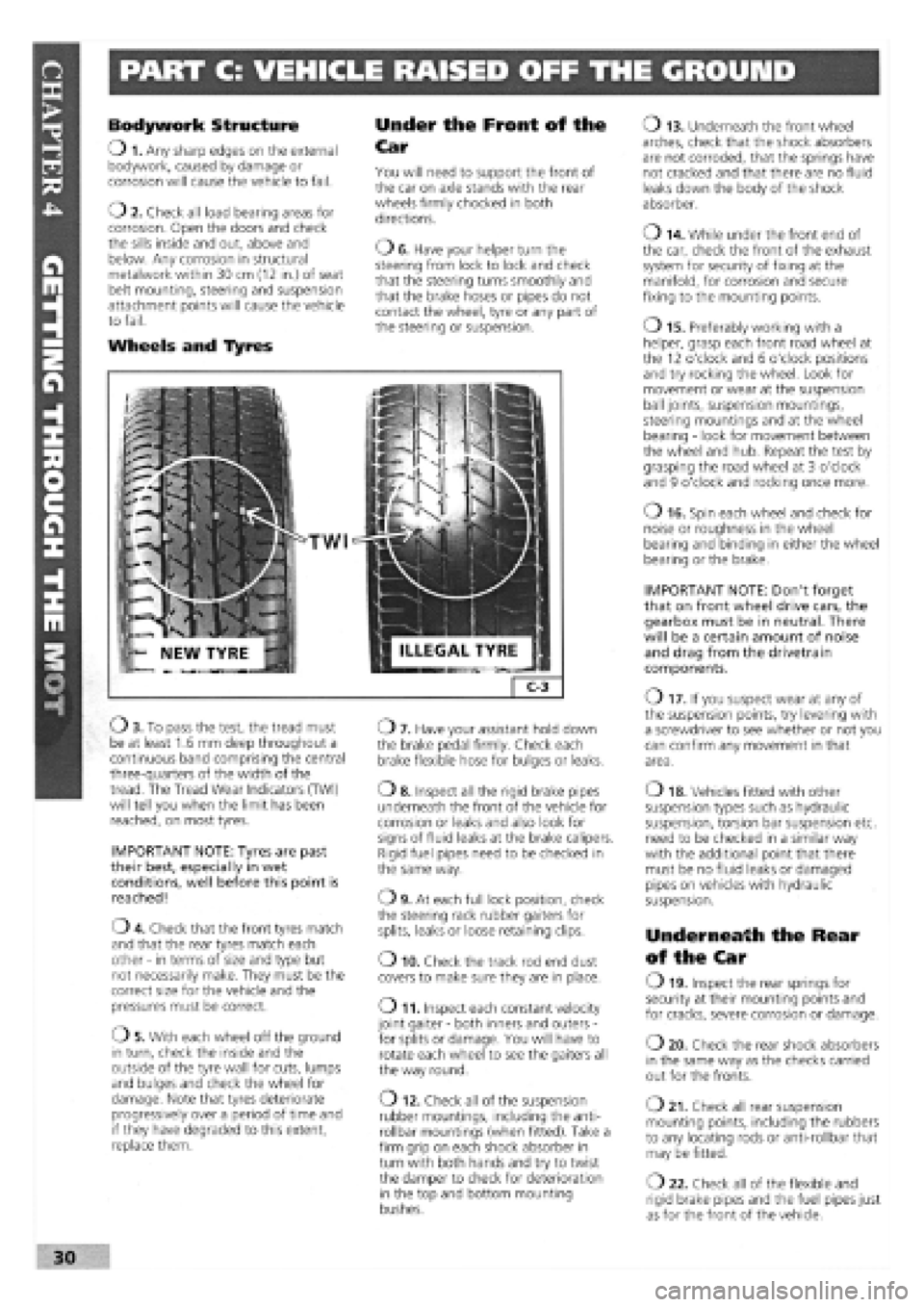
TWI
Ob . To pass the test, the tread must be at least 1.6 mm deep throughout a continuous band comprising the central three-quarters of the width of the tread. The Tread Wear Indicators (TWI) will tell you when the limit has been reached, on most tyres.
IMPORTANT NOTE: Tyres are past their best, especially in wet conditions, well before this point is reached!
04 . Check that the front tyres match and that the rear tyres match each other
-
in terms of size and type but not necessarily make. They must be the correct size for the vehicle and the pressures must be correct.
05 . With each wheel off the ground in turn, check the inside and the outside of the tyre wall for cuts, lumps and bulges and check the wheel for damage. Note that tyres deteriorate progressively over a period of time and if they have degraded to this extent, replace them.
07 . Have your assistant hold down the brake pedal firmly. Check each brake flexible hose for bulges or leaks.
o 8. Inspect all the rigid brake pipes underneath the front of the vehicle for corrosion or leaks and also look for signs of fluid leaks at the brake calipers. Rigid fuel pipes need to be checked in the same way.
09 . At each full lock position, check the steering rack rubber gaiters for splits, leaks or loose retaining clips.
o 10. Check the track rod end dust covers to make sure they are in place.
o 11. Inspect each constant velocity joint gaiter
-
both inners and outers
-
for splits or damage. You will have to rotate each wheel to see the gaiters all the way round.
O 12. Check all of the suspension rubber mountings, including the anti-rollbar mountings (when fitted). Take a firm grip on each shock absorber in turn with both hands and try to twist the damper to check for deterioration in the top and bottom mounting bushes.
o 13. Underneath the front wheel arches, check that the shock absorbers are not corroded, that the springs have not cracked and that there are no fluid leaks down the body of the shock absorber.
o 14. While under the front end of the car, check the front of the exhaust system for security of fixing at the manifold, for corrosion and secure fixing to the mounting points.
o 15. Preferably working with a helper, grasp each front road wheel at the 12 o'clock and 6 o'clock positions and try rocking the wheel. Look for movement or wear at the suspension ball joints, suspension mountings, steering mountings and at the wheel bearing
-
look for movement between the wheel and hub. Repeat the test by grasping the road wheel at 3 o'clock and 9 o'clock and rocking once more.
o 16. Spin each wheel and check for noise or roughness in the wheel bearing and binding in either the wheel bearing or the brake.
IMPORTANT NOTE: Don't forget that on front wheel drive cars, the gearbox must be in neutral. There will be a certain amount of noise and drag from the drivetrain components.
O 17. If you suspect wear at any of the suspension points, try levering with a screwdriver to see whether or not you can confirm any movement in that area.
o 18. Vehicles fitted with other suspension types such as hydraulic suspension, torsion bar suspension etc. need to be checked in a similar way with the additional point that there must be no fluid leaks or damaged pipes on vehicles with hydraulic suspension.
Underneath the Rear
of the Car
O 19. Inspect the rear springs for security at their mounting points and for cracks, severe corrosion or damage.
o 20. Check the rear shock absorbers in the same way as the checks carried out for the fronts.
o 21. Check all rear suspension mounting points, including the rubbers to any locating rods or anti-rollbar that may be fitted.
O 22. Check all of the flexible and rigid brake pipes and the fuel pipes just as for the front of the vehicle.
30
Page 29 of 171
Thanks
are due to the excellent, knowledgeable and helpful staff at FIAT main dealers, Ryauto of Amblecote, in the West
Midlands for supplying vehicles and for their assistance with this chapter. In particular, thanks are due to the efficient Maurice
Hough, Service Manager, the experienced Foreman, Tony Morris, and young demon mechanic, Matthew Worsfold.
Some of the suggested inspection/replacement intervals may not correspond to those shown in the original handbook. The suggested
schedule, based on FIAT'S recommendations, takes into account the age of the vehicle and the annual MoT test in the UK.
In practice, because of the split between (mainly) 12 month/9,000 mile and 18 month/13,500 mile intervals, you will need to
service your Tipo or Tempra at most, if not every, 6 month interval.
IMPORTANT NOTE: Each service should be carried out at EITHER the recommended mileage OR the recommended time
interval, whichever comes first.
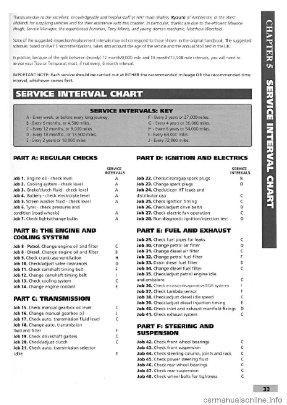
SERVICE INTERVAL CHART
SERVICE INTERVALS: KEY
A
-
Every week, or before every long journey. F
-
Every 3 years or 27,000 miles.
B
-
Every 6 months, or 4,500 miles. G
-
Every 4 years or 36,000 miles.
C - Every 12 months, or 9,000 miles. H
-
Every 6 years or 54,000 miles.
I
-
Every 63,000 miles. D - Every 18 months , or 13,500 miles.
H
-
Every 6 years or 54,000 miles.
I
-
Every 63,000 miles.
E
-
Every 2 years or 18,000 miles J
-
Every 72,000 miles.
PART A: REGULAR CHECKS
SERVICE INTERVALS
Job 1. Engine oil
-
check level A
Job 2. Cooling system
-
check level A
Job 3. Brake/clutch fluid
-
check level A
Job 4. Battery
-
check electrolyte level A
Job 5. Screen washer fluid
-
check level A
Job 6. Tyres
-
check pressures and
condition (road wheels) A
Job 7. Check lights/change bulbs A
PART B: THE ENGINE AND
COOLING SYSTEM
Job 8
-
Petrol. Change engine oil and filter C
Job 8
-
Diesel. Change engine oil and filter B
Job 9. Check crankcase ventilation H
Job 10. Check/adjust valve clearances D
Job 11. Check camshaft timing belt F
Job 12. Change camshaft timing belt I
Job 13. Check cooling system C
Job 14. Change engine coolant E
PART C: TRANSMISSION
Job 15. Check manual gearbox oil level C
Job 16. Change manual gearbox oil J
Job 17. Check auto, transmission fluid level C
Job 18. Change auto, transmission
fluid and filter F
Job 19. Check driveshaft gaiters C
Job 20. Check/adjust clutch C
Job 21. Check auto, transmission selector
cable E
PART D: IGNITION AND ELECTRICS
SERVICE INTERVALS
Job 22. Check/clean/gap spark plugs B
Job 23. Change spark plugs D
Job 24. Check/clean HT leads and
distributor cap C
Job 25. Check ignition timing C
Job 26. Check/adjust drive belt/s D
Job 27. Check electric fan operation C
Job 28. Run diagnostic ignition/injection test D
PART E: FUEL AND EXHAUST
Job 29. Check fuel pipes for leaks C
Job 30. Change petrol air filter D
Job 31. Change diesel air filter C
Job 32. Change petrol fuel filter F
Job 33. Drain diesel fuel filter B
Job 34. Change diesel fuel filter C
Job 35. Check/adjust petrol engine idle
and emissions C
Job 36. Check emission/evaporative/EGR systems F
Job 37. Check Lambda sensor F
Job 38. Check/adjust diesel idle speed C
Job 39. Check/adjust diesel injection timing E
Job 40. Check inlet and exhaust manifold fixings D
Job 41. Check exhaust system C
PART F: STEERING AND
SUSPENSION
Job 42. Check front wheel bearings C
Job 43. Check front suspension C
Job 44. Check steering column, joints and rack C
Job 45. Check power steering fluid C
Job 46. Check rear wheel bearings C
Job 47. Check rear suspension C
Job 48. Check wheel bolts for tightness C
Page 32 of 171
(ignition-ON) position and press down the button between the
two terminals on the reservoir cap
-
when fitted. The warning
light on the dash should light up. When no button is fitted,
unscrew and raise the cap (ignition key ON) to check the
warning light. Check the bulb, check the fuse, or have your
FIAT dealer repair the warning system, if faulty.
• Job 4. Battery
-
check electrolyte level.
FACT FILE: DISCONNECTING THE
BATTERY
• Many vehicles depend on a constant
power supply from the battery; with
these you find yourself in trouble if you
simply disconnect the battery. You
might find the car alarm goes off, or that the engine
management system forgets all it ever 'learned', making
the car feel odd to drive until it has re-programmed
itself. You might also find that the radio refuses to
operate until its correct security code is keyed into it.
• On cars with engine management systems and/or
coded radios, you must ensure the car has a constant
electrical supply, even with the battery removed. You
will need a separate 12 volt battery; put a self-tapping
screw into the positive lead near the battery terminal
before disconnecting it, and put a positive connection
to your other battery via this screw.
• Be EXTREMELY CAREFUL to wrap insulation tape
around the connection so that no short is caused. The
negative terminal on the other battery must be
connected to the car's bodywork.
SAFETY FIRST!
• The gas given off by a battery is highly explosive.
Never smoke, use a naked flame or allow a spark in
the battery compartment.
• Never disconnect the battery (it can cause sparking)
with the battery caps removed.
• All vehicle batteries contain sulphuric acid. If the
acid comes into contact with the skin or eyes, wash
immediately with copious amounts of cold water and
seek medjcal advice.
• Do not check the battery levels within half an hour
of the battery being charged with a separate battery
charger because the addition of fresh water could
cause electrolyte to flood out.
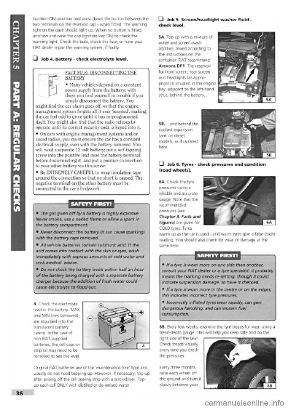
4. Check the electrolyte
level in the battery. MAX
and MIN lines (arrowed)
are moulded into the
translucent battery
casing. In the case of
non-FIAT-supplied
batteries, the cell caps or
strip (a) may need to be
removed to see the level.
Original FIAT batteries are of the 'maintenance-free' type and
usually do not need topping-up. However, if necessary, top up
after prising off the cell sealing strip with a screwdriver. Top-
up each cell ONLY with distilled or de-ionised water.
• Job 5. Screen/headlight washer fluid
check level.
5A. Top up with a mixture of
water and screen-wash
additive, mixed according to
the instructions on the
container. FIAT recommend
Arexons DP1. The reservoir
for front screen, rear screen
and headlights (as appro-
priate) is situated in the engine
bay: adjacent to the left-hand
strut, behind the battery...
5B. ...and behind the
coolant expansion
tank on diesel
models, as illustrated
here.
• Job 6. Tyres
-
check pressures and condition
(road wheels).
/
6A. Check the tyre
pressures using a
reliable and accurate
gauge. Note that the
recommended
pressures (see
Chapter
3,
Facts and
Figures) are given for ^^
iH^KKSEI ^ "'
COLD tyres. Tyres
warm up as the car is used
-
and warm tyres give a false (high)
reading. You should also check for wear or damage at the
same time.
SAFETY FIRST!
• If a tyre is worn more on one side than another,
consult your FIAT dealer or a tyre specialist. It probably
means the tracking needs re-setting, though it could
indicate suspension damage, so have it checked.
• If a tyre is worn more in the centre or on the edges,
this indicates incorrect tyre pressures.
• Incorrectly inflated tyres wear rapidly, can give
dangerous handling, and can worsen fuel
consumption.
Every three months,
raise each wheel off
the ground and turn it
slowly between your
36
6B. Every few weeks, examine the tyre treads for wear using a
tread-depth gauge. This will help you keep safe and on the
right side of the law!
Check treads visually
every time you check
the pressures.
Page 44 of 171
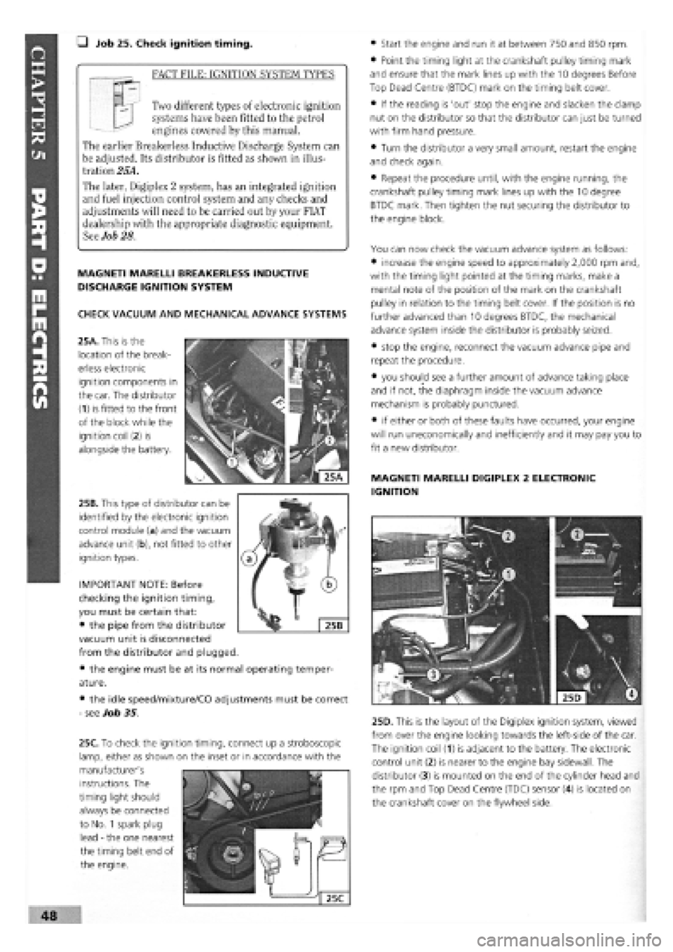
• Job 25. Check ignition timing.
_ FACT FILE: IGNITION SYSTEM TYPES
Two different types of electronic ignition
systems have been fitted to the petrol
engines covered by this manual.
The earlier Breakerless Inductive Discharge System can
be adjusted. Its distributor is fitted as shown in illus-
tration 25A.
The later, Digiplex 2 system, has an integrated ignition
and fuel injection control system and any checks and
adjustments will need to be carried out by your FIAT
dealership with the appropriate diagnostic equipment.
See Job 28.
MAGNETI MARELLI BREAKERLESS INDUCTIVE
DISCHARGE IGNITION SYSTEM
CHECK VACUUM AND MECHANICAL ADVANCE SYSTEMS
25A. This is the
location of the break-
erless electronic
ignition components in
the car. The distributor
(1) is fitted to the front
of the block while the
ignition coil
(2)
is
alongside the battery.
25B. This type of distributor can be
identified by the electronic ignition
control module (a) and the vacuum
advance unit (b), not fitted to other
ignition types.
• the engine must be at
ature.
• the idle speed/mixture/CO adjustments must be correct
-
see Job 35.
• Start the engine and run it at between 750 and 850 rpm.
• Point the timing light at the crankshaft pulley timing mark
and ensure that the mark lines up with the 10 degrees Before
Top Dead Centre (BTDC) mark on the timing belt cover.
• If the reading is 'out' stop the engine and slacken the clamp
nut on the distributor so that the distributor can just be turned
with firm hand pressure.
• Turn the distributor a very small amount, restart the engine
and check again.
• Repeat the procedure until, with the engine running, the
crankshaft pulley timing mark lines up with the 10 degree
BTDC mark. Then tighten the nut securing the distributor to
the engine block.
You can now check the vacuum advance system as follows:
• increase the engine speed to approximately 2,000 rpm and,
with the timing light pointed at the timing marks, make a
mental note of the position of the mark on the crankshaft
pulley in relation to the timing belt cover. If the position is no
further advanced than 10 degrees BTDC, the mechanical
advance system inside the distributor is probably seized.
• stop the engine, reconnect the vacuum advance pipe and
repeat the procedure.
• you should see a further amount of advance taking place
and if not, the diaphragm inside the vacuum advance
mechanism is probably punctured.
• if either or both of these faults have occurred, your engine
will run uneconomical^ and inefficiently and it may pay you to
fit a new distributor.
MAGNETI MARELLI DIGIPLEX 2 ELECTRONIC
IGNITION
25D. This is the layout of the Digiplex ignition system, viewed
from over the engine looking towards the left-side of the car.
The ignition coil (1) is adjacent to the battery. The electronic
control unit (2) is nearer to the engine bay sidewall. The
distributor (3) is mounted on the end of the cylinder head and
the rpm and Top Dead Centre (TDC) sensor (4) is located on
the crankshaft cover on the flywheel side.
IMPORTANT NOTE: Before
checking the ignition timing,
you must be certain that:
• the pipe from the distributor
vacuum unit is disconnected
from the distributor and plugged.
its normal operating temper-
instructions. The
timing light should
always be connected
to No.
1
spark plug
lead
-
the one nearest
the timing belt end of
the engine.
48
25C. To check the ignition timing, connect up a stroboscopic
lamp, either as shown on the inset or in accordance with the
manufacturer's
Page 48 of 171
• Job 32. Change petrol fuel filter. IMPORTANT NOTES:
• Wear plastic gloves and goggles and have a large rag
and a suitable fire extinguisher ready.
• Place a container beneath the filter to catch fuel
spillage.
• After fitting the new filter in place, refit the casing,
ensure no traces of fuel are left, reconnect the battery and
restart the engine.
• Check carefully to ensure there are no leaks before
refitting the cover.
• Job 33. Drain diesel fuel filter.
IMPORTANT NOTE: Some models are fitted with a water-
in-fuel sensor. Drain the filter when the warning light
comes on. Unplug the sensor from the base of the filter,
first.
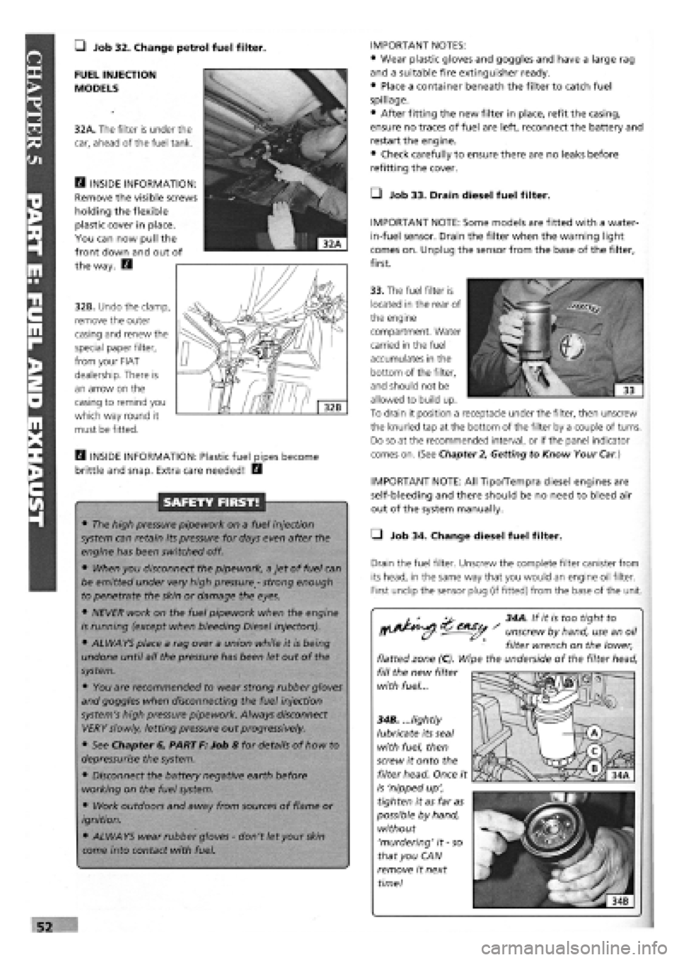
FUEL INJECTION
MODELS
32A. The filter is under the
car, ahead of the fuel tank.
E3 INSIDE INFORMATION:
Remove the visible screws
holding the flexible
plastic cover in place.
You can now pull the
front down and out of
the way. E3
32B. Undo the clamp,
remove the outer
casing and renew the
special paper filter,
from your FIAT
dealership. There is
an arrow on the
casing to remind you
which way round it
must be fitted.
33. The fuel filter is
located in the rear of
the engine
compartment. Water
carried in the fuel
accumulates in the
bottom of the filter,
and should not be
allowed to build up.
To drain it position a receptacle under the filter, then unscrew
the knurled tap at the bottom of the filter by a couple of turns.
Do so at the recommended interval, or if the panel indicator
comes on. (See Chapter
2,
Getting to Know Your
Car.)
H INSIDE INFORMATION: Plastic fuel pipes become
brittle and snap. Extra care needed! E3
SAFETY FIRST!
• The high pressure pipework on a fuel injection
system can retain its pressure for days even after the
engine has been switched off.
• When you disconnect the pipework, a jet of fuel can
be emitted under very high pressure
-
strong enough
to penetrate the skin or damage the eyes.
• NEVER work on the fuel pipework when the engine
is running (except when bleeding Diesel injectors).
• ALWAYS place a rag over a union while it is being
undone until all the pressure has been let out of the
system.
• You are recommended to wear strong rubber gloves
and goggles when disconnecting the fuel injection
system's high pressure pipework. Always disconnect
VERY slowly, letting pressure out progressively.
• See Chapter 6, PART F: Job 8 for details of how to
depressurise the system.
• Disconnect the battery negative earth before
working on the fuel system.
• Work outdoors and away from sources of flame or
ignition.
• ALWAYS wear rubber gloves
-
don't let your
skin
come into contact with fuel.
IMPORTANT NOTE: All Tipo/Tempra diesel engines are
self-bleeding and there should be no need to bleed air
out of the system manually.
• Job 34. Change diesel fuel filter.
Drain the fuel filter. Unscrew the complete filter canister from
its head, in the same way that you would an engine oil filter.
First undip the sensor plug (if fitted) from the base of the unit.
^ 34A. If it is too tight to
^^ - unscrew by hand, use an oil
filter wrench on the lower,
flatted zone (C). Wipe the underside of the filter head,
fill the new filter
with fuel...
34B. ...lightly
lubricate its seal
with fuel, then
screw it onto the
filter head. Once it
is 'nipped up',
tighten it as far as
possible by hand,
without
'murdering' it
-
so
that you CAN
remove it next
time!