gearbox FIAT TEMPRA 1988 Service And Repair Manual
[x] Cancel search | Manufacturer: FIAT, Model Year: 1988, Model line: TEMPRA, Model: FIAT TEMPRA 1988Pages: 171, PDF Size: 18.05 MB
Page 2 of 171
Running The Vehicle
NEVER start the engine unless the gearbox is in neutral (or
'Park' in the case of automatic transmission) and the hand
brake is fully applied.
NEVER run catalytic converter equipped vehicles without the
exhaust system heat shields in place.
TAKE CARE when parking vehicles fitted with catalytic
converters. The 'cat' reaches extremely high temperatures and
any combustible materials under the car, such as long dry
grass, could be ignited.
Personal Safety
NEVER siphon fuel, antifreeze, brake fluid or other such toxic
liquids by mouth, or allow contact with your skin. Use a
suitable hand pump and wear gloves.
BEFORE undertaking dirty jobs, use a barrier cream on your
hands as a protection against infection. Preferably, wear
suitable gloves, available from DIY outlets.
WEAR IMPERVIOUS GLOVES for sure when there is a risk of
used engine oil coming into contact with your skin. It can
cause cancer.
WIPE UP any spilt oil, grease or water off the floor
immediately.
MAKE SURE that spanners and all other tools are the right size
for the job and are not likely to slip. Never try to 'double-up'
spanners to gain more leverage.
SEEK HELP if you need to lift something heavy which may be
beyond your capability. Don't forget that when lifting a heavy
weight, you should keep your back straight and bend your
knees to avoid injuring your back.
NEVER take risky short-cuts or rush to finish a job. Plan ahead
and allow plenty of time.
BE METICULOUS and keep the work area tidy
-
you'll avoid
frustration, work better and lose less.
KEEP children and animals right-away from the work area and
from unattended vehicles.
ALWAYS tell someone what you're doing and have them
regularly check that all is well, especially when working alone
on, or under, the vehicle.
Fire!
Petrol (gasoline) is a dangerous and highly flammable liquid
requiring special precautions. When working on the fuel
system, disconnect the vehicle battery earth (ground) terminal
whenever possible and always work outside, or in a very well
ventilated area. Any form of spark, such as that caused by an
electrical fault, by two metal surfaces striking against each
other, by a central heating boiler in the garage 'firing up', or
even by static electricity built up in your clothing can, in a
confined space, ignite petrol vapour causing an explosion.
Take great care not to spill petrol on to the engine or exhaust
system, never allow any naked flame anywhere near the work
area and, above all, don't smoke.
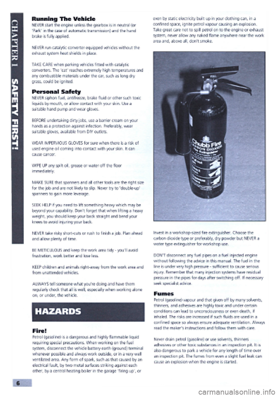
Invest in a workshop-sized fire extinguisher. Choose the
carbon dioxide type or preferably, dry powder but NEVER a
water type extinguisher for workshop use.
DON'T disconnect any fuel pipes on a fuel injected engine
without following the advice in this manual. The fuel in the
line is under very high pressure
-
sufficient to cause serious
injury. Remember that many injection systems have residual
pressure in the pipes for days after switching off. If necessary
seek specialist advice.
Fumes
Petrol (gasoline) vapour and that given off by many solvents,
thinners, and adhesives are highly toxic and under certain
conditions can lead to unconsciousness or even death, if
inhaled. The risks are increased if such fluids are used in a
confined space so always ensure adequate ventilation. Always
read the maker's instructions and follow them with care.
Never drain petrol (gasoline) or use solvents, thinners
adhesives or other toxic substances in an inspection pit. It is
also dangerous to park a vehicle for any length of time over
an inspection pit. The fumes from even a slight fuel leak can
cause an explosion when the engine is started.
v ,,, Oil;::;s
Page 4 of 171
and explosions. Do not allow resin or 2-pack adhesive hardener,
or that supplied with filler or 2-pack stopper, to come into
contact with skin or eyes. Read carefully the safety notes
supplied on the can, tube or packaging and always wear
impervious gloves and goggles when working with them.
Fluoroelastomers
Fluoroelastomers are commonly used for oil seals, wiring and
cabling, bearing surfaces, gaskets, diaphragms, hoses and '0'
rings. If they are subjected to temperatures greater than 315
degrees C, they will decompose and can be potentially
hazardous. Some decomposition may occur at temperatures
above 200 degrees C, and it is obvious that when a car has
been in a fire or has been dismantled with the assistance of a
cutting torch or blow torch, the fluoroelastomers can
decompose in the manner indicated above.
According to the Health and Safety Executive, "Skin contact
with this liquid or decomposition residues can cause painful and
penetrating burns. Permanent irreversible skin and tissue
damage can occur". Damage can also be caused to eyes or by
the inhalation of fumes created as fluoroelastomers are burned
or heated.
After a vehicle has been exposed to fire or high temperatures:
1. Do not touch blackened or charred seals or equipment.
2. Preferably, don't handle parts containing decomposed
fluoroelastomers, but if you must, wear goggles and PVC
(polyvinyl chloride) or neoprene protective gloves whilst doing
so. Never handle such parts unless they are completely cool.
3. Contaminated parts, residues, materials and clothing,
including protective clothing and gloves, should be disposed of
by an approved contractor to landfill or by incineration
according to national or local regulations. Oil seals, gaskets and
'0' rings, along with contaminated material, must not
be burned.
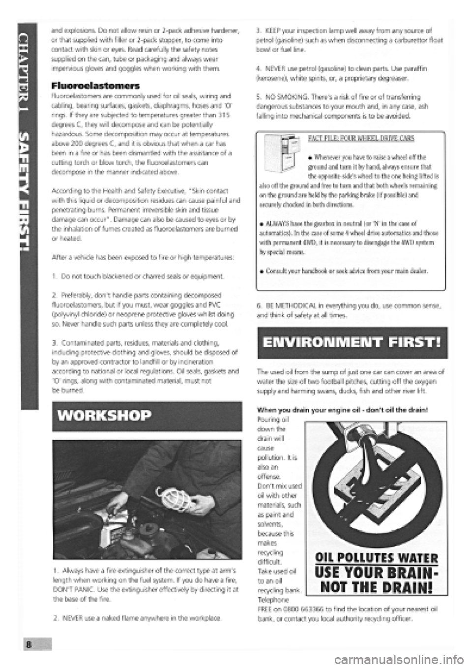
1. Always have a fire extinguisher of the correct type at arm's
length when working on the fuel system. If you do have a fire,
DON'T PANIC. Use the extinguisher effectively by directing it at
the base of the fire.
2. NEVER use a naked flame anywhere in the workplace.
3. KEEP your inspection lamp well away from any source of
petrol (gasoline) such as when disconnecting a carburettor float
bowl or fuel line.
4. NEVER use petrol (gasoline) to clean parts. Use paraffin
(kerosene), white spirits, or, a proprietary degreaser.
5. NO SMOKING. There's a risk of fire or of transferring
dangerous substances to your mouth and, in any case, ash
falling into mechanical components is to be avoided.
FACT FILE: FOUR WHEEL DRIVE CARS
• Whenever you have to raise a wheel off the
ground and turn it by hand, always ensure that
the opposite-side's wheel to the one being lifted is
also off the ground and free to turn and that both wheels remaining
on the ground are held by the parking brake (if possible) and
securely chocked in both directions.
• ALWAYS have the gearbox in neutral (or 'N' in the case of
automatics). In the case of
some
4 wheel drive automatics and those
with permanent 4WD, it is necessary to disengage the 4WD system
by special means.
• Consult your handbook or seek advice from your main dealer.
6. BE METHODICAL in everything you do, use common sense,
and think of safety at all times.
ENVIRONMENT FIRST!
The used oil from the sump of
just
one car
can
cover
an
area of
water the size of two football pitches, cutting off the oxygen
supply
and
harming swans, ducks, fish and other river lift.
When you drain your engine oil
-
don't oil the drain!
Pouring oil
down the
drain will
cause
pollution. It is
also an
offense.
Don't mix used
oil with other
materials, such
as paint and
solvents,
because this
makes
recycling
difficult.
Take used oil
to an oil
recycling bank.
Telephone
FREE on 0800 663366 to find the location of your nearest oil
bank, or contact you local authority recycling officer.
OIL POLLUTES WATER
USE YOUR BRAIN-
NOT THE DRAIN!
Page 12 of 171
EMERGENCY STARTING
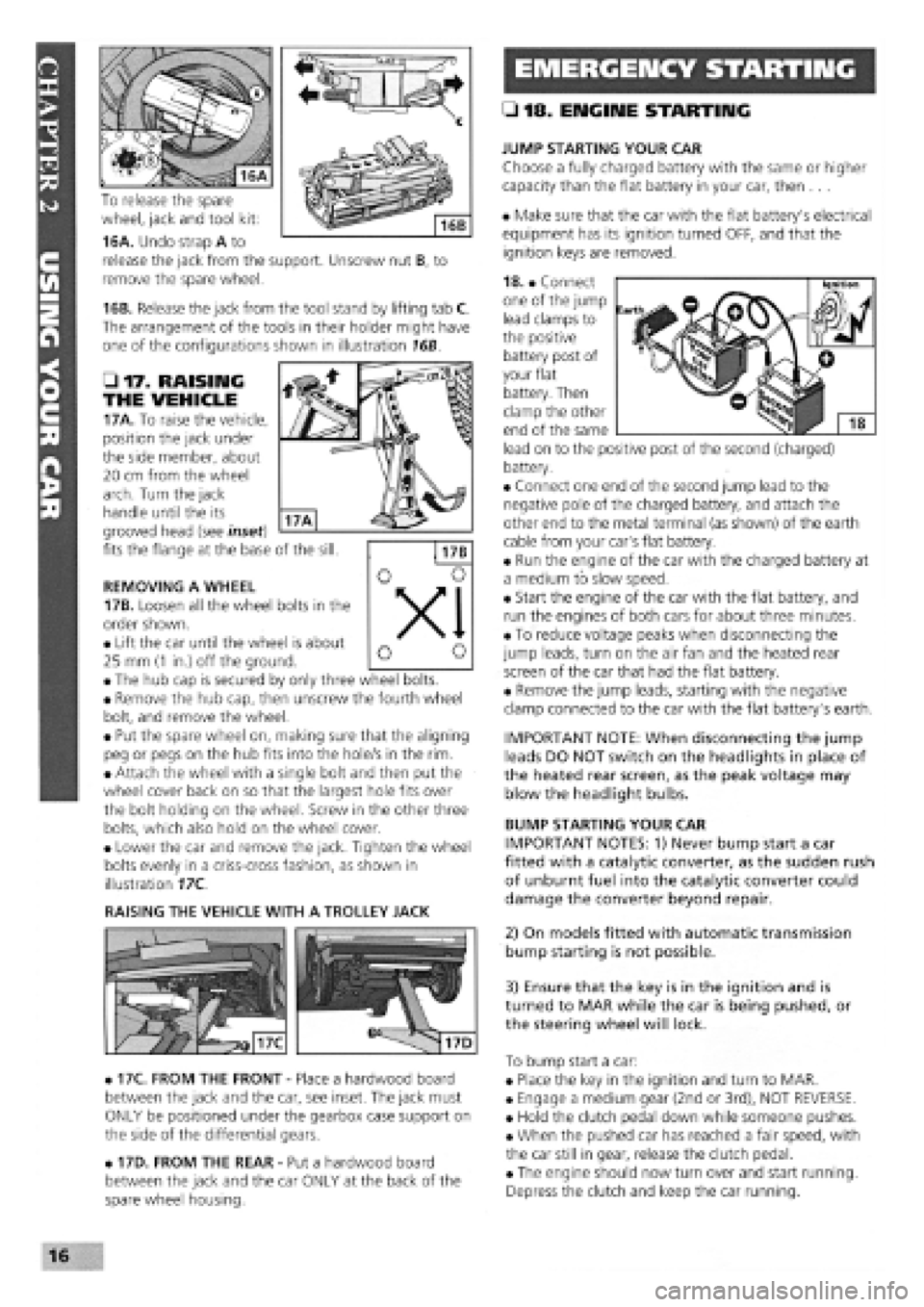
To release the spare
wheel, jack and tool kit:
16A. Undo strap A to
release the jack from the support. Unscrew nut B, to
remove the spare wheel.
16B. Release the jack from the tool stand by lifting tab C.
The arrangement of the tools in their holder might have
one of the configurations shown in illustration 16B.
• 17. RAISING
THE VEHICLE
17A. To raise the vehicle,
position the jack under
the side member, about
20 cm from the wheel
arch. Turn the jack
handle until the its
grooved head (see inset)
fits the flange at the base of the sill.
REMOVING A WHEEL
17B. Loosen all the wheel bolts in the
order shown.
• Lift the car until the wheel is about
25 mm
(1
in.) off the ground.
• The hub cap is secured by only three wheel bolts.
• Remove the hub cap, then unscrew the fourth wheel
bolt, and remove the wheel.
• Put the spare wheel on, making sure that the aligning
peg or pegs on the hub fits into the hole/s in the rim.
• Attach the wheel with a single bolt and then put the
wheel cover back on so that the largest hole fits over
the bolt holding on the wheel. Screw in the other three
bolts, which also hold on the wheel cover.
• Lower the car and remove the jack. Tighten the wheel
bolts evenly in a criss-cross fashion, as shown in
illustration 17C.
RAISING THE VEHICLE WITH A TROLLEY JACK
• 17C. FROM THE FRONT
-
Place a hardwood board
between the jack and the car, see inset. The jack must
ONLY be positioned under the gearbox case support on
the side of the differential gears.
• 17D. FROM THE REAR
-
Put a hardwood board
between the jack and the car ONLY at the back of the
spare wheel housing.
• 18. ENGINE STARTING
JUMP STARTING YOUR CAR
Choose a fully charged battery with the same or higher
capacity than the flat battery in your car, then ...
• Make sure that the car with the flat battery's electrical
equipment has its ignition turned OFF, and that the
ignition keys are removed.
18. • Connect
one of the jump
lead clamps to
the positive
battery post of
your flat
battery. Then
clamp the other
end of the same
lead on to the positive post of the second (charged)
battery.
• Connect one end of the second jump lead to the
negative pole of the charged battery, and attach the
other end to the metal terminal (as shown) of the earth
cable from your car's flat battery.
• Run the engine of the car with the charged battery at
a medium to slow speed.
• Start the engine of the car with the flat battery, and
run the engines of both cars for about three minutes.
• To reduce voltage peaks when disconnecting the
jump leads, turn on the air fan and the heated rear
screen of the car that had the flat battery.
• Remove the jump leads, starting with the negative
clamp connected to the car with the flat battery's earth.
IMPORTANT NOTE: When disconnecting the jump
leads DO NOT switch on the headlights in place of
the heated rear screen, as the peak voltage may
blow the headlight bulbs.
BUMP STARTING YOUR CAR
IMPORTANT NOTES: 1) Never bump start a car
fitted with a catalytic converter, as the sudden rush
of unburnt fuel into the catalytic converter could
damage the converter beyond repair.
2) On models fitted with automatic transmission
bump starting is not possible.
3) Ensure that the key is in the ignition and is
turned to MAR while the car is being pushed, or
the steering wheel will lock.
To bump start a car:
• Place the key in the ignition and turn to MAR.
• Engage a medium gear (2nd or 3rd), NOT REVERSE.
• Hold the clutch pedal down while someone pushes.
• When the pushed car has reached a fair speed, with
the car still in gear, release the clutch pedal.
• The engine should now turn over and start running.
Depress the clutch and keep the car running.
16
Page 13 of 171
CHAPTER 3
FACTS ARID FIGURES
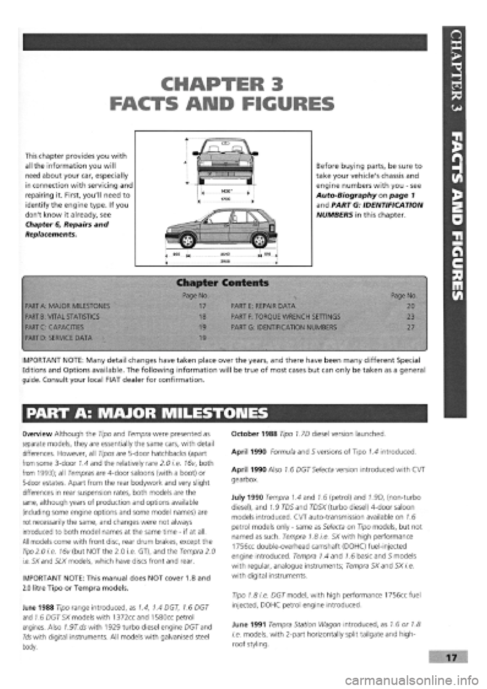
This chapter provides you with
all the information you will
need about your car, especially
in connection with servicing and
repairing it. First, you'll need to
identify the engine type. If you
don't know it already, see
Chapter 6, Repairs and
Replacements.
Before buying parts, be sure to
take your vehicle's chassis and
engine numbers with you
-
see
Auto-Biography on page 1
and PART G: IDENTIFICATION
NUMBERS in this chapter.
Chapter Contents
• -< Page No. Page No.
PART
A:
MAJOR MILESTONES 17 PART E: REPAIR DATA 20
PART
B:
VITAL STATISTICS 18 PART
F:
TORQUE WRENCH SETTINGS 23
PART C: CAPACITIES 19 PART G: IDENTIFICATION NUMBERS 27
PART
D:
SERVICE DATA 19
•
IMPORTANT NOTE: Many detail changes have taken place over the years, and there have been many different Special
Editions and Options available. The following information will be true of most cases but can only be taken as a general
guide. Consult your local FIAT dealer for confirmation.
PART A: MAJOR MILESTONES
Overview Although the Tipo and Tempra were presented as
separate models, they are essentially the same cars, with detail
differences. However, all Tipos are 5-door hatchbacks (apart
from some 3-door 1.4 and the relatively rare 2.0 i.e. 16v, both
from 1993); all Tempras are 4-door saloons (with a boot) or
5-door estates. Apart from the rear bodywork and very slight
differences in rear suspension rates, both models are the
same, although years of production and options available
(including some engine options and some model names) are
not necessarily the same, and changes were not always
introduced to both model names at the same time
-
if at all.
All models come with front disc, rear drum brakes, except the
Tipo
2.0 i.e. 16v (but NOT the 2.0 i.e. GT), and the Tempra 2.0
i.e. SXand SLX models, which have discs front and rear.
IMPORTANT NOTE: This manual does NOT cover 1.8 and
2.0 litre Tipo or Tempra models.
June 1988 Tipo range introduced, as 1.4, 1.4 DGT, 1.6 DGT
and 1.6 DGT SX models with 1372ccand 1580cc petrol
engines. Also 7.97".dswith 1929 turbo diesel engine DGT and
Ids with digital instruments. All models with galvanised steel
body.
October 1988 Tipo 1.7D diesel version launched.
April 1990 Formula and S versions of Tipo 1.4 introduced.
April 1990 Also 1.6 DGT Selecta version introduced with CVT
gearbox.
July 1990 Tempra 1.4 and 1.6 (petrol) and 1.9D, (non-turbo
diesel), and 1.9 TD5 and TD5X (turbo diesel) 4-door saloon
models introduced. CVT auto-transmission available on 1.6
petrol models only
-
same as Selecta on Tipo models, but not
named as such. Tempra 1.8 i.e. SX with high performance
1756cc double-overhead camshaft (DOHC) fuel-injected
engine introduced. Tempra 1.4 and 1.6 basic and 5 models
with regular, analogue instruments; Tempra SXand SX i.e.
with digital instruments.
Tipo 1.8 i.e. DGT model, with high performance 1756cc fuel
injected, DOHC petrol engine introduced.
June 1991 Tempra Station Wagon introduced, as 1.6 or 1.8
i.e. models, with 2-part horizontally split tailgate and high-
roof styling.
Page 14 of 171
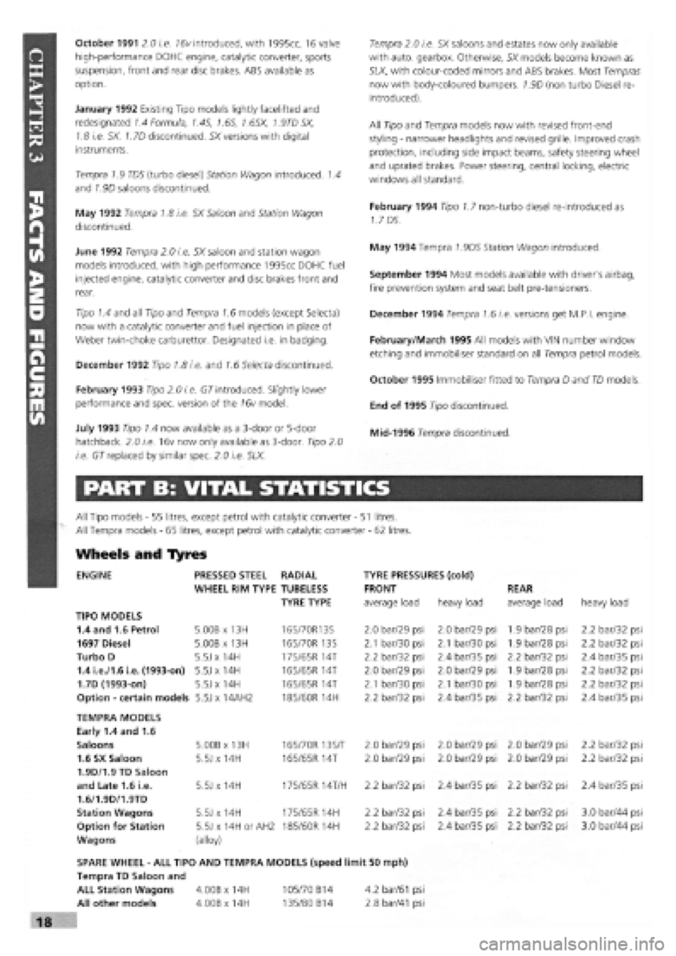
October 1991 2.0 i.e. 16v introduced, with 1995cc, 16 valve
high-performance DOHC engine, catalytic converter, sports
suspension, front and rear disc brakes. ABS available as
option.
January 1992 Existing Tipo models lightly facelifted and
redesignated 1.4 Formula, 1.45, 1.6S, 1.6SX, 1.9TD SX,
1.8 i.e. SX. 1.7D discontinued. SX versions with digital
instruments.
Tempra 1.9 TDS (turbo diesel) Station Wagon introduced. 1.4
and 1.9D saloons discontinued.
May 1992 Tempra 1.8 i.e. SX Saloon and Station Wagon
discontinued.
June 1992 Tempra 2.0 i.e. SX saloon and station wagon
models introduced, with high performance 1995cc DOHC fuel
injected engine, catalytic converter and disc brakes front and
rear.
Tipo 1.4 and all Tipo and Tempra 1.6 models (except Selecta)
now with a catalytic converter and fuel injection in place of
Weber twin-choke carburettor. Designated i.e. in badging.
December 1992 Tipo 1.8 i.e. and 1.6 Selecta discontinued.
February 1993 Tipo 2.0 i.e. GT introduced. Slightly lower
performance and spec, version of the 16v model.
July 1993 Tipo 1.4 now available as a 3-door or 5-door
hatchback. 2.0 i.e. 16v now only available as 3-door. Tipo 2.0
i.e. GT replaced by similar spec. 2.0 i.e. SLX.
Tempra 2.0 i.e. SX saloons and estates now only available
with auto, gearbox. Otherwise, SX models become known as
SLX, with colour-coded mirrors and ABS brakes. Most Tempras
now with body-coloured bumpers. 1.9D (non turbo Diesel re-
introduced).
All Tipo and Tempra models now with revised front-end
styling
-
narrower headlights and revised grille. Improved crash
protection, including side impact beams, safety steering wheel
and uprated brakes. Power steering, central locking, electric
windows all standard.
February 1994 Tipo 1.7 non-turbo diesel re-introduced as
1.7 DS.
May 1994 Tempra 1.9DS Station Wagon introduced.
September 1994 Most models available with driver's airbag,
fire prevention system and seat belt pre-tensioners.
December 1994 Tempra 1.6 i.e. versions get M.P.I, engine.
February/March 1995 All models with VIN number window
etching and immobiliser standard on all Tempra petrol models.
October 1995 Immobiliser fitted to Tempra D and TD models.
End of 1995 Tipo discontinued.
Mid-1996 Tempra discontinued.
PART B: VITAL STATISTICS
All Tipo models
-
55 litres, except petrol with catalytic converter
- 51
litres.
All Tempra models
-
65 litres, except petrol with catalytic converter
-
62 litres.
Wheels and Tyres
ENGINE PRESSED STEEL RADIAL TYRE PRESSURES (cold)
WHEEL RIM TYPE TUBELESS FRONT REAR
TYRE TYPE average load heavy load average load heavy load
TIPO MODELS
1.4 and 1.6 Petrol 5.00B x 13H 165/70R13S 2.0 bar/29 psi 2.0 bar/29 psi 1.9 bar/28 psi 2.2 bar/32 psi
1697 Diesel 5.00B x 13H 165/70R 13S 2.1 bar/30 psi 2.1 bar/30 psi 1.9 bar/28 psi 2.2 bar/32 psi
Turbo D 5.5J x 14H
175/65 R
14T 2.2 bar/32 psi 2.4 bar/35 psi 2.2 bar/32 psi 2.4 bar/35 psi
1.4 i.e./1.6 i.e. (1993-on) 5.5J x 14H
165/65 R
14T 2.0 bar/29 psi 2.0 bar/29 psi 1.9 bar/28 psi 2.2 bar/32 psi
1.7D (1993-on) 5.5J x 14H 165/65R 14T 2.1 bar/30 psi 2.1 bar/30 psi 1.9 bar/28 psi 2.2 bar/32 psi
Option
-
certain models 5.5J x 14AH2 185/60R 14H 2.2 bar/32 psi 2.4 bar/35 psi 2.2 bar/32 psi 2.4 bar/35 psi
TEMPRA MODELS
Early 1.4 and 1.6
Saloons 5.00B x 13H 165/70R 13S/T 2.0 bar/29 psi 2.0 bar/29 psi 2.0 bar/29 psi 2.2 bar/32 psi
1.6 SX Saloon 5.5J x 14H 165/65R 14T 2.0 bar/29 psi 2.0 bar/29 psi 2.0 bar/29 psi 2.2 bar/32 psi
1.9D/1.9 TD Saloon
and Late 1.6 i.e. 5.5J x 14H 175/65R 14T/H 2.2 bar/32 psi 2.4 bar/35 psi 2.2 bar/32 psi 2.4 bar/35 psi
1.6/1.9D/1.9TD
Station Wagons 5.5J x 14H 175/65R 14H 2.2 bar/32 psi 2.4 bar/35 psi 2.2 bar/32 psi 3.0 bar/44 psi
Option for Station 5.5J x 14H or AH2 185/60 R 14H 2.2 bar/32 psi 2.4 bar/35 psi 2.2 bar/32 psi 3.0 bar/44 psi
Wagons (alloy)
SPARE WHEEL
-
ALL TIPO AND TEMPRA MODELS (speed limit 50 mph)
Tempra TD Saloon and
ALL Station Wagons 4.00B x 14H 105/70 B14 4.2
bar/61
psi
All other models 4.00Bx14H 135/80 B14 2.8
bar/41
psi
Page 20 of 171
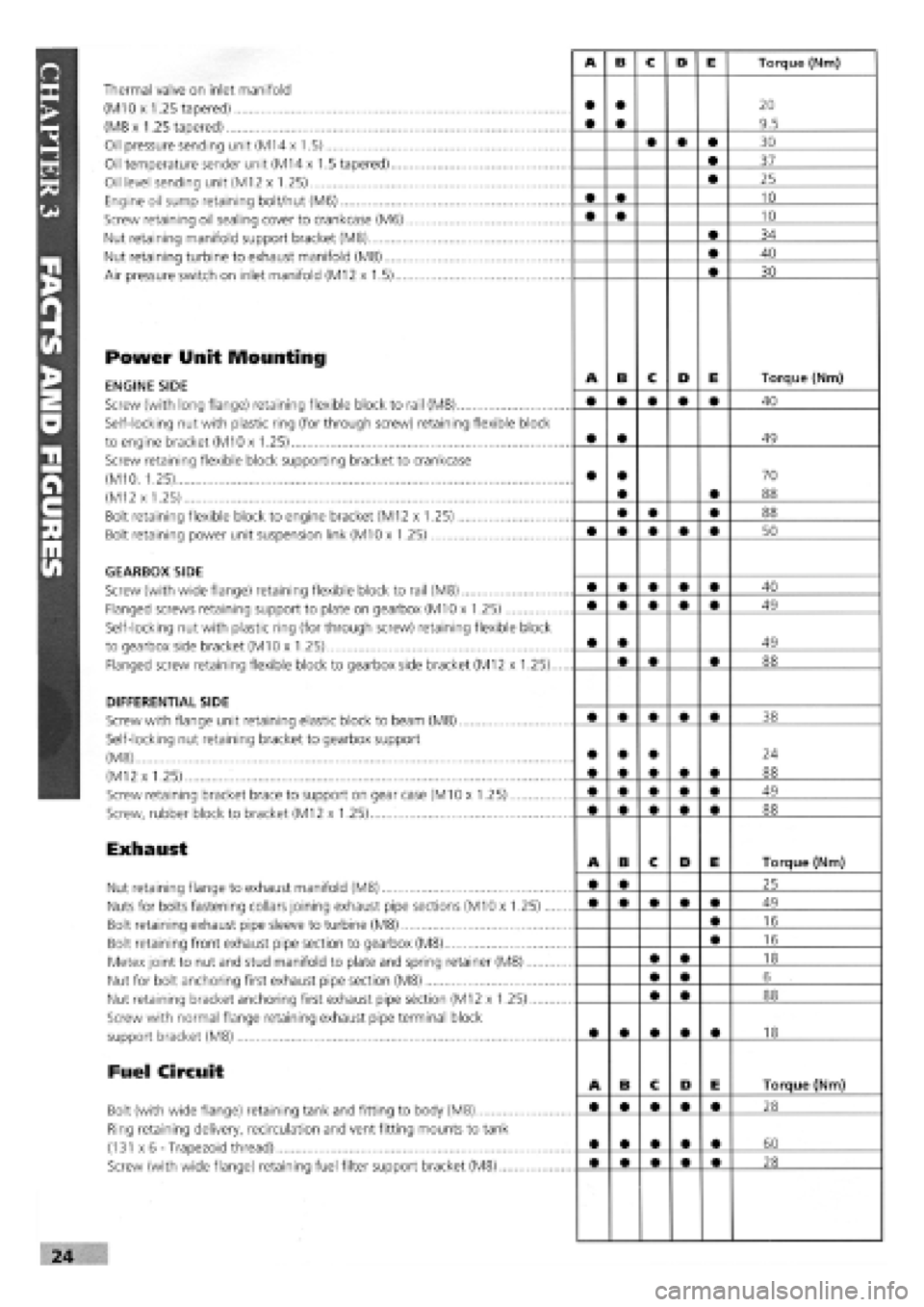
Thermal valve on inlet manifold
(M10 x 1.25 tapered)
(M8 x 1.25 tapered)
Oil pressure sending unit (M14 x 1.5)
Oil temperature sender unit (M14 x 1.5 tapered)....
Oil level sending unit (M12 x 1.25)
Engine oil sump retaining bolt/nut (M6)
Screw retaining oil sealing cover to crankcase (M6)
Nut retaining manifold support bracket (M8)
Nut retaining turbine to exhaust manifold (M8)
Air pressure switch on inlet manifold (M12 x 1.5)...
Power Unit Mounting
ENGINE SIDE
Screw (with long flange) retaining flexible block to rail (M8)
Self-locking nut with plastic ring (for through screw) retaining flexible block
to engine bracket (M10 x 1.25)
Screw retaining flexible block supporting bracket to crankcase
(M10. 1.25)
(M12 x 1.25)
Bolt retaining flexible block to engine bracket (M12 x 1.25)
Bolt retaining power unit suspension link (M10 x 1.25)
GEARBOX SIDE
Screw (with wide flange) retaining flexible block to rail (M8)
Flanged screws retaining support to plate on gearbox (M10 x 1.25)
Self-locking nut with plastic ring (for through screw) retaining flexible block
to gearbox side bracket (M10 x 1.25)
Flanged screw retaining flexible block to gearbox side bracket (M12 x 1.25).
DIFFERENTIAL SIDE
Screw with flange unit retaining elastic block to beam (M8)
Self-locking nut retaining bracket to gearbox support
(M8)
(M12 x 1.25)
Screw retaining bracket brace to support on gear case (M10 x 1.25)
Screw, rubber block to bracket (M12 x 1.25)
Exhaust
Nut retaining flange to exhaust manifold (M8)
Nuts for bolts fastening collars joining exhaust pipe sections (M10 x 1.25)...
Bolt retaining exhaust pipe sleeve to turbine (M8)
Bolt retaining front exhaust pipe section to gearbox (M8)
Metex joint to nut and stud manifold to plate and spring retainer (M8)
Nut for bolt anchoring first exhaust pipe section (M8)
Nut retaining bracket anchoring first exhaust pipe section (M12 x 1.25)
Screw with normal flange retaining exhaust pipe terminal block
support bracket (M8)
Fuel Circuit
Bolt (with wide flange) retaining tank and fitting to body (M8)
Ring retaining delivery, recirculation and vent fitting mounts to tank
(131 x 6-Trapezoid thread)
Screw (with wide flange) retaining fuel filter support bracket (M8)
Page 21 of 171
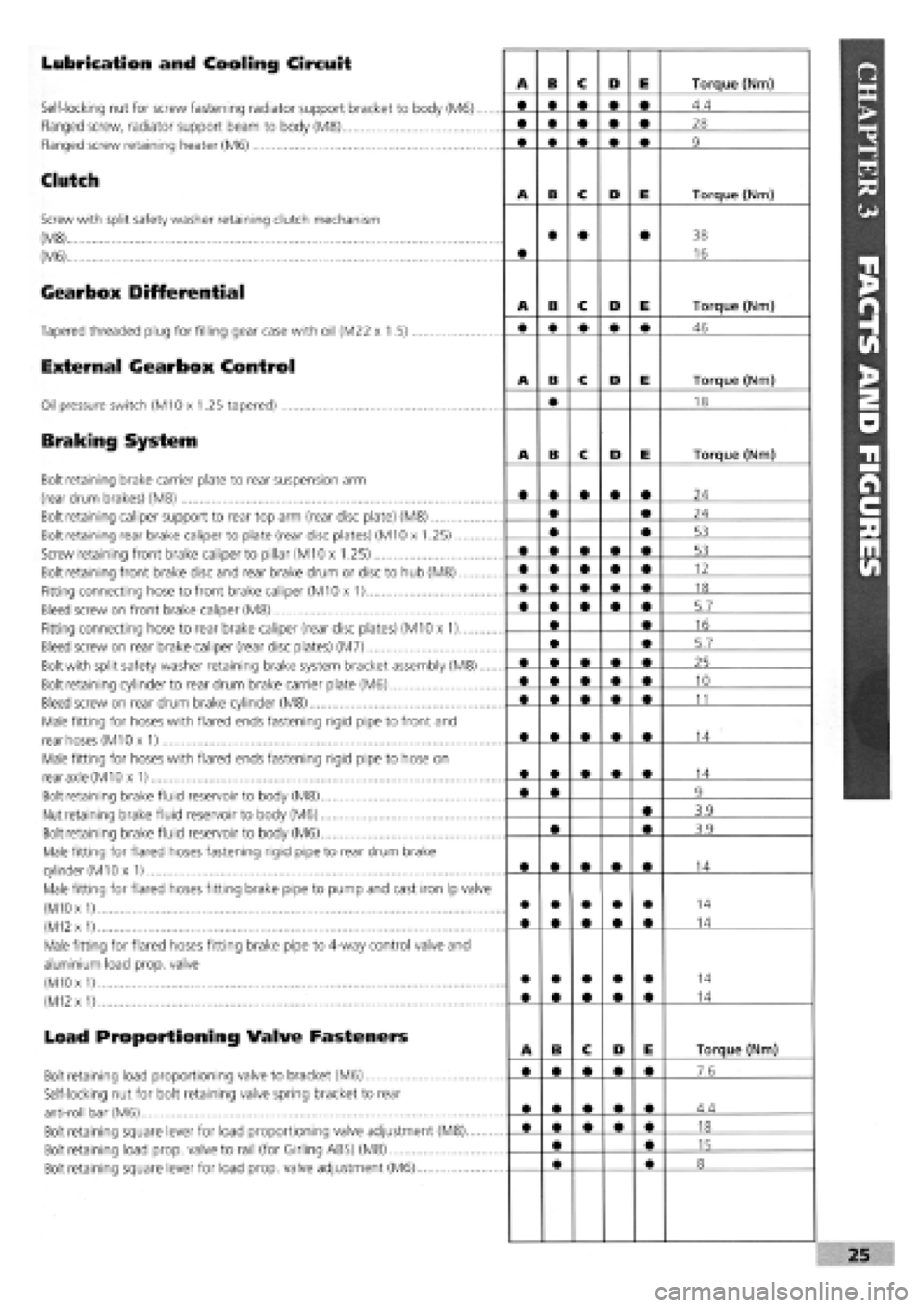
Lubrication and Cooling Circuit
Self-locking nut for screw fastening radiator support bracket to body (M6)....
Flanged screw, radiator support beam to body (M8)
Flanged screw retaining heater (M6)
Clutch
Screw with split safety washer retaining clutch mechanism
(M8)
(M6)
Gearbox Differential
Tapered threaded plug for filling gear case with oil (M22 x 1.5)
External Gearbox Control
Oil pressure switch (M10 x 1.25 tapered)
Braking System
Bolt retaining brake carrier plate to rear suspension arm
(rear drum brakes) (M8)
Bolt retaining caliper support to rear top arm (rear disc plate) (M8)
Bolt retaining rear brake caliper to plate (rear disc plates) (M10 x 1.25)
Screw retaining front brake caliper to pillar (M10 x 1.25)
Bolt retaining front brake disc and rear brake drum or disc to hub (M8)
Fitting connecting hose to front brake caliper (M10 x 1)
Bleed screw on front brake caliper (M8)
Fitting connecting hose to rear brake caliper (rear disc plates) (M10 x 1)
Bleed screw on rear brake caliper (rear disc plates) (M7)
Bolt with split safety washer retaining brake system bracket assembly (M8)....
Bolt retaining cylinder to rear drum brake carrier plate (M6)
Bleed screw on rear drum brake cylinder (M8)
Male fitting for hoses with flared ends fastening rigid pipe to front and
rear hoses (M10 x 1)
Male fitting for hoses with flared ends fastening rigid pipe to hose on
rear axle (M10 x 1)
Bolt retaining brake fluid reservoir to body (M8)
Nut retaining brake fluid reservoir to body (M6)
Bolt retaining brake fluid reservoir to body (M6)
Male fitting for flared hoses fastening rigid pipe to rear drum brake
cylinder
(M1
Ox 1)
Male fitting for flared hoses fitting brake pipe to pump and cast iron Ip valve
(M10
x
1)
(M12
x
1)
Male fitting for flared hoses fitting brake pipe to 4-way control valve and
aluminium load prop, valve
(M10 x
1)
(M12
x
1)
Load Proportioning Valve Fasteners
Bolt retaining load proportioning valve to bracket (M6)
Self-locking nut for bolt retaining valve spring bracket to rear
anti-roll bar (M6)
Bolt retaining square lever for load proportioning valve adjustment (M8)
Bolt retaining load prop, valve to rail (for Girling ABS) (M8)
Bolt retaining square lever for load prop, valve adjustment (M6)
Page 23 of 171
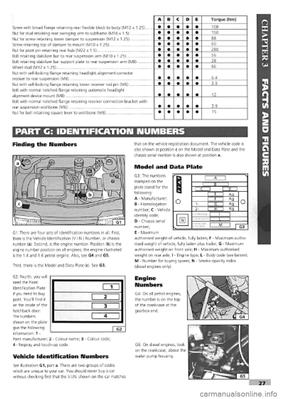
Screw with broad flange retaining rear flexible block to body (M12 x 1.25)..
Nut for stud retaining rear swinging arm to subframe (M16 x 1.5)
Nut for screw retaining lower damper to suspension (M12 x 1.25)
Screw retaining top of damper to mount (M10 x 1.25)
Nut for pivot pin retaining rear hub (M22 x 1.5)
Bolt retaining stabilizer bar to rear suspension arm (M10 x 1.25)
Bolt retaining stabilizer bar support plate to rear suspension arm (M8)
Wheel stud (M12 x 1.25)
Nut with self-locking flange retaining headlight alignment corrector
receiver to rear suspension (M8)
Nut with self-locking flange retaining lower receiver rod pin (M6)
Bolt with normal notched flange retaining automatic headlight
alignment device mount (M8)
Bolt with normal notched flange retaining receiver connection bracket with
rear suspension wishbone (M6)
Nut for bolt retaining square lever to wishbone (M8)
A B c D E Torque (Nm)
• • • • • 108
• • • • • 150
• • • • • 88
• • • • • 60
• • • • • 280
• • • • • 56
• • • • • 28
• • • • • 86
• • • • • 6.4
• • • • • 3.9
• • • • • 12
• • • • • 3.9
• • • • • 15
PART G: IDENTIFICATION NUMBERS
Finding the Numbers
G1: There are four sets of identification numbers in all. First,
there is the Vehicle Identification (V.I.N.) Number, or chassis
number (a). Second, is the engine number. Position (b) is the
engine number position on all engines; the engine illustrated
is
the 1.4 and 1.6 petrol engine. Also, see G4 and G5.
Third, there is the Model and Data Plate (c). See G3.
G2: Fourth, you will
need the Paint
Identification Plate
if you need to buy
paint. You'll find it
on the inside of the
hatchback door.
The numbers
shown on the plate
give the following
information: 1 -
Paint manufacturer; 2
-
Colour name; 3
-
Colour code;
4
-
Respray and touch-up code.
Vehicle Identification Numbers
See illustration G1, part a. There are two groups of codes
which are unique to your car. You should never buy a car
without checking first that the V.I.N, shown on the car matches
that on the vehicle registration document. The vehicle code is
also shown at position c on the Model and Data Plate and the
chassis serial number is also shown at position a.
Model and Data Plate
G3: The numbers
stamped on the
plate stand for the
following:
A
-
Manufacturer;
B
-
Homologation
number; C
-
Vehicle
identity code;
D
-
Chassis serial
number;
E
-
Maximum
authorised weight of vehicle, fully laden; F
-
Maximum autho-
rised weight of vehicle, fully laden plus trailer; G
-
Maximum
authorised weight on front axle; H
-
Maximum authorised
weight on rear axle; I
-
Engine type; L
-
Body code (see below);
M - Number for buying spares; N
-
Smoke opacity index
(diesel engines only).
Engine
Numbers
G4: On all petrol engines,
the number is on the top
of the crankcase at the
gearbox end.
G5: On diesel engines, look
on the crankcase, above the
water pump housing.
1
2
3
4
G2
r
B
r
B I B I
r
B
C I D I
r
B
I E I Kn
o o I F I Kq o o 1- I <3 I Kq o o
2- | H I Kq
o
MOTORE ENGINE
I I
N VERSIONE-VERSION •f
PER RICAM8:
N*
FOR SPARED
L I
1 G3
Page 26 of 171
PART C: VEHICLE RAISED OFF THE GROUND
Bodywork Structure
01
.
Any sharp edges on the external bodywork, caused by damage or corrosion will cause the vehicle to fail.
02 . Check all load bearing areas for corrosion. Open the doors and check the sills inside and out, above and below. Any corrosion in structural metalwork within 30 cm (12 in.) of seat belt mounting, steering and suspension attachment points will cause the vehicle to fail.
Wheels and Tyres
Under the Front of the
Car
You will need to support the front of the car on axle stands with the rear wheels firmly chocked in both directions.
OE . Have your helper turn the steering from lock to lock and check that the steering turns smoothly and that the brake hoses or pipes do not contact the wheel, tyre or any part of the steering or suspension.
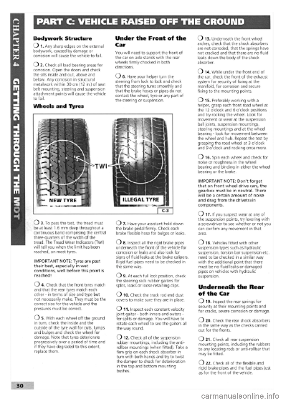
TWI
Ob . To pass the test, the tread must be at least 1.6 mm deep throughout a continuous band comprising the central three-quarters of the width of the tread. The Tread Wear Indicators (TWI) will tell you when the limit has been reached, on most tyres.
IMPORTANT NOTE: Tyres are past their best, especially in wet conditions, well before this point is reached!
04 . Check that the front tyres match and that the rear tyres match each other
-
in terms of size and type but not necessarily make. They must be the correct size for the vehicle and the pressures must be correct.
05 . With each wheel off the ground in turn, check the inside and the outside of the tyre wall for cuts, lumps and bulges and check the wheel for damage. Note that tyres deteriorate progressively over a period of time and if they have degraded to this extent, replace them.
07 . Have your assistant hold down the brake pedal firmly. Check each brake flexible hose for bulges or leaks.
o 8. Inspect all the rigid brake pipes underneath the front of the vehicle for corrosion or leaks and also look for signs of fluid leaks at the brake calipers. Rigid fuel pipes need to be checked in the same way.
09 . At each full lock position, check the steering rack rubber gaiters for splits, leaks or loose retaining clips.
o 10. Check the track rod end dust covers to make sure they are in place.
o 11. Inspect each constant velocity joint gaiter
-
both inners and outers
-
for splits or damage. You will have to rotate each wheel to see the gaiters all the way round.
O 12. Check all of the suspension rubber mountings, including the anti-rollbar mountings (when fitted). Take a firm grip on each shock absorber in turn with both hands and try to twist the damper to check for deterioration in the top and bottom mounting bushes.
o 13. Underneath the front wheel arches, check that the shock absorbers are not corroded, that the springs have not cracked and that there are no fluid leaks down the body of the shock absorber.
o 14. While under the front end of the car, check the front of the exhaust system for security of fixing at the manifold, for corrosion and secure fixing to the mounting points.
o 15. Preferably working with a helper, grasp each front road wheel at the 12 o'clock and 6 o'clock positions and try rocking the wheel. Look for movement or wear at the suspension ball joints, suspension mountings, steering mountings and at the wheel bearing
-
look for movement between the wheel and hub. Repeat the test by grasping the road wheel at 3 o'clock and 9 o'clock and rocking once more.
o 16. Spin each wheel and check for noise or roughness in the wheel bearing and binding in either the wheel bearing or the brake.
IMPORTANT NOTE: Don't forget that on front wheel drive cars, the gearbox must be in neutral. There will be a certain amount of noise and drag from the drivetrain components.
O 17. If you suspect wear at any of the suspension points, try levering with a screwdriver to see whether or not you can confirm any movement in that area.
o 18. Vehicles fitted with other suspension types such as hydraulic suspension, torsion bar suspension etc. need to be checked in a similar way with the additional point that there must be no fluid leaks or damaged pipes on vehicles with hydraulic suspension.
Underneath the Rear
of the Car
O 19. Inspect the rear springs for security at their mounting points and for cracks, severe corrosion or damage.
o 20. Check the rear shock absorbers in the same way as the checks carried out for the fronts.
o 21. Check all rear suspension mounting points, including the rubbers to any locating rods or anti-rollbar that may be fitted.
O 22. Check all of the flexible and rigid brake pipes and the fuel pipes just as for the front of the vehicle.
30
Page 29 of 171
Thanks
are due to the excellent, knowledgeable and helpful staff at FIAT main dealers, Ryauto of Amblecote, in the West
Midlands for supplying vehicles and for their assistance with this chapter. In particular, thanks are due to the efficient Maurice
Hough, Service Manager, the experienced Foreman, Tony Morris, and young demon mechanic, Matthew Worsfold.
Some of the suggested inspection/replacement intervals may not correspond to those shown in the original handbook. The suggested
schedule, based on FIAT'S recommendations, takes into account the age of the vehicle and the annual MoT test in the UK.
In practice, because of the split between (mainly) 12 month/9,000 mile and 18 month/13,500 mile intervals, you will need to
service your Tipo or Tempra at most, if not every, 6 month interval.
IMPORTANT NOTE: Each service should be carried out at EITHER the recommended mileage OR the recommended time
interval, whichever comes first.
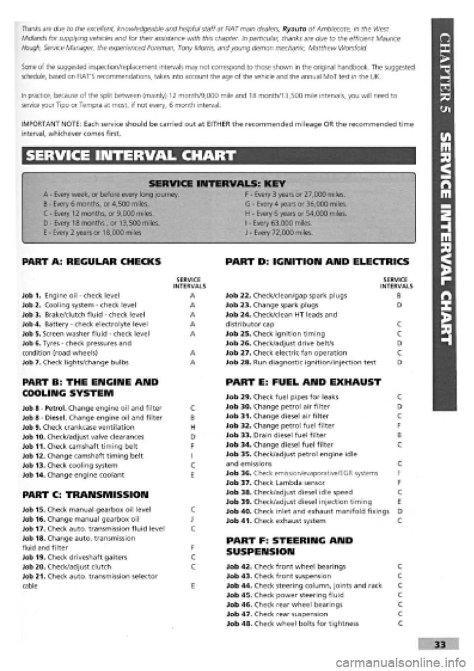
SERVICE INTERVAL CHART
SERVICE INTERVALS: KEY
A
-
Every week, or before every long journey. F
-
Every 3 years or 27,000 miles.
B
-
Every 6 months, or 4,500 miles. G
-
Every 4 years or 36,000 miles.
C - Every 12 months, or 9,000 miles. H
-
Every 6 years or 54,000 miles.
I
-
Every 63,000 miles. D - Every 18 months , or 13,500 miles.
H
-
Every 6 years or 54,000 miles.
I
-
Every 63,000 miles.
E
-
Every 2 years or 18,000 miles J
-
Every 72,000 miles.
PART A: REGULAR CHECKS
SERVICE INTERVALS
Job 1. Engine oil
-
check level A
Job 2. Cooling system
-
check level A
Job 3. Brake/clutch fluid
-
check level A
Job 4. Battery
-
check electrolyte level A
Job 5. Screen washer fluid
-
check level A
Job 6. Tyres
-
check pressures and
condition (road wheels) A
Job 7. Check lights/change bulbs A
PART B: THE ENGINE AND
COOLING SYSTEM
Job 8
-
Petrol. Change engine oil and filter C
Job 8
-
Diesel. Change engine oil and filter B
Job 9. Check crankcase ventilation H
Job 10. Check/adjust valve clearances D
Job 11. Check camshaft timing belt F
Job 12. Change camshaft timing belt I
Job 13. Check cooling system C
Job 14. Change engine coolant E
PART C: TRANSMISSION
Job 15. Check manual gearbox oil level C
Job 16. Change manual gearbox oil J
Job 17. Check auto, transmission fluid level C
Job 18. Change auto, transmission
fluid and filter F
Job 19. Check driveshaft gaiters C
Job 20. Check/adjust clutch C
Job 21. Check auto, transmission selector
cable E
PART D: IGNITION AND ELECTRICS
SERVICE INTERVALS
Job 22. Check/clean/gap spark plugs B
Job 23. Change spark plugs D
Job 24. Check/clean HT leads and
distributor cap C
Job 25. Check ignition timing C
Job 26. Check/adjust drive belt/s D
Job 27. Check electric fan operation C
Job 28. Run diagnostic ignition/injection test D
PART E: FUEL AND EXHAUST
Job 29. Check fuel pipes for leaks C
Job 30. Change petrol air filter D
Job 31. Change diesel air filter C
Job 32. Change petrol fuel filter F
Job 33. Drain diesel fuel filter B
Job 34. Change diesel fuel filter C
Job 35. Check/adjust petrol engine idle
and emissions C
Job 36. Check emission/evaporative/EGR systems F
Job 37. Check Lambda sensor F
Job 38. Check/adjust diesel idle speed C
Job 39. Check/adjust diesel injection timing E
Job 40. Check inlet and exhaust manifold fixings D
Job 41. Check exhaust system C
PART F: STEERING AND
SUSPENSION
Job 42. Check front wheel bearings C
Job 43. Check front suspension C
Job 44. Check steering column, joints and rack C
Job 45. Check power steering fluid C
Job 46. Check rear wheel bearings C
Job 47. Check rear suspension C
Job 48. Check wheel bolts for tightness C