handbrake FIAT TEMPRA 1988 Service And Repair Manual
[x] Cancel search | Manufacturer: FIAT, Model Year: 1988, Model line: TEMPRA, Model: FIAT TEMPRA 1988Pages: 171, PDF Size: 18.05 MB
Page 6 of 171
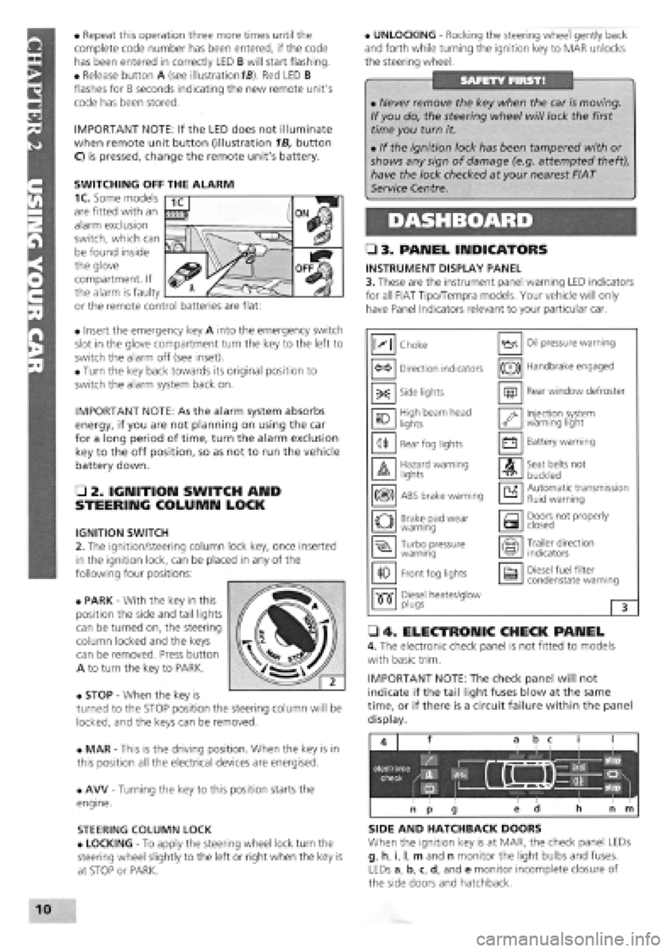
• Repeat this operation three more times until the
complete code number has been entered, if the code
has been entered in correctly LED B will start flashing.
• Release button A (see illustration
1B).
Red LED B
flashes for 8 seconds indicating the new remote unit's
code has been stored.
IMPORTANT NOTE: If the LED does not illuminate
when remote unit button (illustration 1B, button
O is pressed, change the remote unit's battery.
• Insert the emergency key A into the emergency switch
slot in the glove compartment turn the key to the left to
switch the alarm off (see inset).
• Turn the key back towards its original position to
switch the alarm system back on.
IMPORTANT NOTE: As the alarm system absorbs
energy, if you are not planning on using the car
for a long period of time, turn the alarm exclusion
key to the off position, so as not to run the vehicle
battery down.
• 2. IGNITION SWITCH AND
STEERING COLUMN LOCK
IGNITION SWITCH
2. The ignition/steering column lock key, once inserted
in the ignition lock, can be placed in any of the
following four positions:
• PARK
-
With the key in this
position the side and tail lights
can be turned on, the steering
column locked and the keys
can be removed. Press button
A to turn the key to PARK.
• STOP
-
When the key is
turned to the STOP position the steering column will be
locked, and the keys can be removed.
• MAR
-
This is the driving position. When the key is in
this position all the electrical devices are energised.
• AW
-
Turning the key to this position starts the
engine.
STEERING COLUMN LOCK
• LOCKING
-
To apply the steering wheel lock turn the
steering wheel slightly to the left or right when the key is
at STOP or PARK.
• UNLOCKING
-
Rocking the steering wheel gently back
and forth while turning the ignition key to MAR unlocks
the steering wheel.
• 3. PANEL INDICATORS
INSTRUMENT DISPLAY PANEL
3. These are the instrument panel warning LED indicators
for all FIAT Tipo/Tempra models. Your vehicle will only
have Panel Indicators relevant to your particular car.
• 4. ELECTRONIC CHECK PANEL
4. The electronic check panel is not fitted to models
with basic trim.
IMPORTANT NOTE: The check panel will not
indicate if the tail light fuses blow at the same
time, or if there is a circuit failure within the panel
display.
SIDE AND HATCHBACK DOORS
When the ignition key is at MAR, the check panel LEDs
g, h, i, I, m and n monitor the light bulbs and fuses.
LEDs a, b, c, d, and e monitor incomplete closure of
the side doors and hatchback.
• Never remove the key when the car is moving.
If you do, the steering wheel will lock the first
time you turn it.
• If the ignition lock has been tampered with or
shows any sign of damage (e.g. attempted theft),
have the lock checked at your nearest FIAT
Service Centre.
M Choke Oil pressure warning
Direction indicators (®) Handbrake engaged
-X: Side lights m Rear window defroster
10 High beam head
lights '•y Injection system warning light
<1* Rear fog lights • Battery warning
A Hazard warning lights A Seat belts not
buckled
m ABS brake warning a Automatic transmission fluid warning
o Brake pad wear warning a Doors not properly closed
Turbo pressure warning Trailer direction indicators
10 Front fog lights a Diesel fuel filter condenstate warning
•515" Diesel heater/glow •515" plugs 3
SWITCHING OFF THE ALARM
1C. Some models
are fitted with an
alarm exclusion
switch, which can
be found inside
the glove
compartment. If
the alarm is faulty
or the remote control batteries are flat:
Page 10 of 171
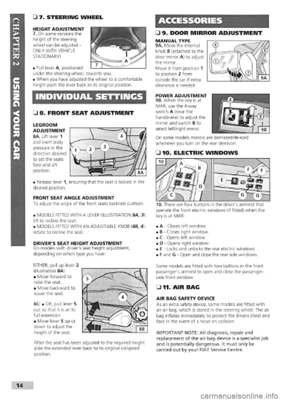
• 9. DOOR MIRROR ADJUSTMENT
• 7. STEERING WHEEL
HEIGHT ADJUSTMENT
7. On some versions the
height of the steering
wheel can be adjusted -
ONLY WITH VEHICLE
STATIONARY!
• Pull lever A, positioned
under the steering wheel, towards you.
• When you have adjusted the wheel to a comfortable
height push the lever back to its original position.
MANUAL TYPE 9A. Move the internal
knob B (attached to the
door mirror A) to adjust
the mirror.
Move it from position 1
to position 2 from
outside the car if extra
clearance is needed.
INDIVIDUAL SETTINGS POWER ADJUSTMENT
9B. When the key is at
MAR, use the 4-way
switch A (near the
handbrake) to adjust the
mirror and switch B to
select left/right mirror.
On some models mirrors are demisted/de-iced
whenever you turn on the rear demister.
• 8. FRONT SEAT ADJUSTMENT
LEGROOM
ADJUSTMENT
8A. Lift lever 1
and exert body
pressure in the
direction desired
to set the seats
fore-and-aft
position:
• Release lever 1, ensuring that the seat is locked in the
desired position.
FRONT SEAT ANGLE ADJUSTMENT
To adjust the angle of the front seats backrest cushion:
• MODELS FITTED WITH A LEVER (ILLUSTRATION 8A, 3):
lift to recline the seat.
• MODELS FITTED WITH AN ADJUSTABLE KNOB (8B, 4):
rotate to recline the seat.
DRIVER'S SEAT HEIGHT ADJUSTMENT
On models with driver's seat height adjustment,
depending on which type you have:
EITHER, pull up lever 2
(illustration &4):
• Move forward to
raise the seat.
• Move backward to
lower the seat.
8C: • OR, pull lever 5
out so that it is at its
full extension.
• Move lever 5 up or
down to adjust the
height of the seat.
After the seat has been adjusted to the required height
slide the extended lever back to its original collapsed
position.
• 10. ELECTRIC WINDOWS
operate the front electric windows (if fitted) when the
key is at MAR:
• A
-
Closes left window.
• B
-
Closes right window.
• C
-
Opens left window.
• D
-
Opens right window.
• E
-
Locks and unlocks the rear electric windows.
• F and G
-
Open and close the rear side windows.
Some models are fitted with two buttons in the front
passenger's armrest to open and close the passenger-
side front window.
• 11. AIR BAG
AIR BAG SAFETY DEVICE
As an extra safety device, some models are fitted with
an air bag, which is stored in the steering wheel. The air
bag inflates immediately to protect the drivers chest and
face in the event of a head on collision.
IMPORTANT NOTE: All diagnosis, repair and
replacement of the air bag device is a specialist job
and is potentially dangerous. It must only be
carried out by your FIAT Service Centre.
I
Page 11 of 171
SAFETY FIRST!
If an air bag has been fitted to your vehicle:
• DO NOT apply stickers or any other objects to
the steering wheel as this may restrict the
operation of the air bag.
• NEVER travel with anything on your lap or in
front of your chest
• NEVER drive with a cigarette, pipe, pen or any
other object in your mouth.
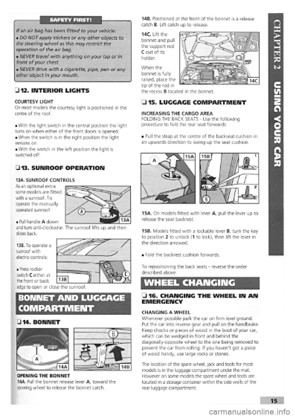
• 12. INTERIOR LIGHTS
COURTESY LIGHT
On most models the courtesy light is positioned in the
centre of the roof.
• With the light switch in the central position the light
turns on when either of the front doors is opened.
• When the switch is in the right position the light
remains on.
• With the switch in the left position the light is
switched off.
• 13. SUNROOF OPERATION
14B. Positioned at the front of the bonnet is a release
catch B. Lift catch up to release.
14C. Lift the
bonnet and pull
the support rod
C out of its
holder.
When the
• 15. LUGGAGE COMPARTMENT
INCREASING THE CARGO AREA
FOLDING THE BACK SEATS
-
Use the following
procedure to fold the rear seat forwards:
• Pull the strap at the centre of the backseat cushion in
an upwards direction to swing up the seat cushion.
15A. On models fitted with lever A, pull the lever up to
release the seat backrest.
15B. Models fitted with a lockable lever B, turn the key
to position 2 to unlock (1 to lock), then lift the lever in
the direction arrowed.
• Fold the backrest cushion forwards.
BONNET AND LUGGAGE
L 2 . fj§
• 14 .BONNET
OPENING THE BONNET
14A. Pull the bonnet release lever A, toward the
steering wheel to release the bonnet catch.
To repositioning the back seats
-
reverse the order
described above.
WHEEL CHANGING
• 16. CHANGING THE WHEEL IN AN
EMERGENCY
CHANGING A WHEEL
Whenever possible park the car on firm level ground.
Put the car into reverse gear and pull on the handbrake.
Keep chocks or pieces of wood in the boot of your car,
which can be wedged in front and behind the
diagonally-opposite wheel to the one being removed to
prevent the car from rolling. If you haven't got a piece
of wood handy, use large rocks or stones.
The location of the spare wheel, jack and tools for most
models is in the luggage compartment under the mat.
However on some models the spare wheel and tools are
located in a storage container within the side walls of the
rear luggage compartment.
bonnet is fully
raised, place the
tip of the rod in
the recess B located in the bonnet.
• Pull handle A down
and turn anti-clockwise,
slides back.
13B. To operate a
sunroof with
electric controls:
13A. SUNROOF CONTROLS
As an optional extra
some models are fitted
with a sunroof. To
operate the manually
operated sunroof:
The sunroof lifts up and then
• Press rocker
switch C either at
the front or back
edge to open or close the sunroof.
Z3
Page 22 of 171
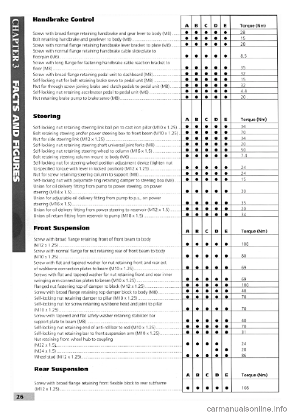
Handbrake Control
Screw with broad flange retaining handbrake and gear lever to body (M8)
Bolt retaining handbrake and gearlever to body (M8)
Screw with normal flange retaining handbrake lever bracket to plate (M8)
Screw with normal flange retaining handbrake cable slide plate to
floorpan (M6)
Screw with long flange for fastening handbrake cable reaction bracket to
floor (M8)
Screw with broad flange retaining pedal unit to dashboard (M8)
Self-locking nut for bolt retaining brake servo to pedal unit (M8)
Nut for through screw joining brake and clutch pedals to pedal unit (M8).
Self-locking nut retaining accelerator pedal to pedal unit (M6)
Nut retaining brake pump to brake servo (M8)
Steering
Self-locking nut retaining steering link ball pin to cast iron pillar (M10 x 1.25)..
Bolt retaining steering and/or power steering box to front beam (M10 x 1.25).
Nut for side steering link (M12 x 1.25)
Self-locking nut retaining steering shaft universal joint forks (M8)
Self-locking nut retaining steering wheel to column (M16 x 1.5)
Bolt retaining steering column mount to body (M6)
Self-locking nut for steering wheel position adjustment device (tighten nut
to specified torque with lever in locked position) (M12 x 1.25)
Nut for screw retaining steering column to support (M8)
Self-locking nut with polyamide ring retaining damper to steering box (M8)
Union for oil delivery fitting from pump to power steering, on power
steering (M14 x 1.5)
Union for adjustable oil delivery fitting from pump to p.s., on power
steering (M16 x 1.5)
Union for oil delivery fitting from power steering to reservoir (M12 x 1.5)
Union oil return fitting from reservoir to pump (M18 x 1.5)
Front Suspension
Screw with broad flange retaining front of front beam to body
(M12 x 1.25)
Screw with normal flange for nut retaining rear of front beam to body
(M10
x
1.25)
Screw with flat and tapered washer for nut retaining front and rear ext.
of wishbone connection plates to beam (M10 x 1.25)
Screws with flat and tapered washer for nut retaining front and rear inner
swinging arm connection plates to beam (M10 x 1.25)
Flanged nut fastening top of damper to block (M12 x 1.25)
Screw with broad flange retaining top damper block to body (M8)
Self-locking nut retaining damper to pillar (M10 x 1.25)
Self-locking nut for screw retaining wishbone head and joint to pillar
(M10
x
1.25)
Screw with tapered and flat safety washer retaining stabilizer bar
support plate to beam (M8)
Self-locking nut retaining end of anti-roll bar to rod (M10 x 1.25)
Self-locking nut retaining bar to front suspension arm (M10 x 1.25)
Nut retaining front wheel hub to coupling
(M22 x 1.5)i
(M24
x
1.5)
Wheel stud (M12 x 1.25).....
Rear Suspension
Screw with broad flange retaining front flexible block to rear subframe
(M12 x 1.25)
A B C D E Torque (Nm)
• • • • • 28
• • • • • 15
• • • • • 28
8.5
35
32
15
32
4.4
20 .
A B C D E Torque (Nm)
• • • • • 34
70
34
• • • • • 20
50
7.4
24
24
15
30
35
20
34
A B c D E Torque (Nm)
108
80
69
69
100
40
70
70
40
70
31
• • • • • •
24
28
86
A B c D E Torque (Nm)
108
Page 25 of 171
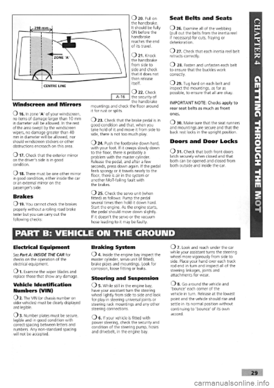
Windscreen and Mirrors
O 16. In zone 'A' of your windscreen, no items of damage larger than 10 mm in diameter will be allowed. In the rest of the area swept by the windscreen wipers, no damage greater than 40 mm in diameter will be allowed, nor should windscreen stickers or other obstructions encroach on this area.
o 17. Check that the exterior mirror on the driver's side is in good condition.
o 18. There must be one other mirror in good condition, either inside the car or an external mirror on the passenger's side.
Brakes
O 19. You cannot check the brakes
properly without a rolling road brake
tester but you can carry out the
following checks:
O 20. Pull on the handbrake. It should be fully ON before the handbrake reaches the end of its travel.
O 21. Knock the handbrake from side to side and check that it does not then release itself.
O 22. Check the security of the handbrake mountings and check the floor around it for rust or splits.
o 23. Check that the brake pedal is in good condition and that, when you take hold of it and move it from side to side, there is not too much play.
o 24. Push the footbrake down hard, with your foot. If it creeps slowly down to the floor, there is probably a problem with the master cylinder. Release the pedal, and after a few seconds, press down again. If the pedal feels spongy or it travels nearly to the floor, there is air in the system or another MoT-failing fault with the brakes.
o 25. Check the servo unit (when
fitted) as follows: Pump the pedal
several times then hold it down hard.
Start the engine. As the engine starts,
the pedal should move down slightly.
If it doesn't the servo or the vacuum
hose leading to it may be faulty.
Seat Belts and Seats
O 26. Examine all of the webbing (pull out the belts from the inertia reel if necessary) for cuts, fraying or deterioration.
o 27. Check that each inertia reel belt retracts correctly.
o 28. Fasten and unfasten each belt to ensure that the buckles work correctly.
o 29. Tug hard on each belt and inspect the mountings, as far as possible, to ensure that all are okay.
IMPORTANT NOTE: Checks apply to
rear seat belts as much as front
ones.
O 30. Make sure that the seat runners and mountings are secure and that the back rest locks in the upright position.
Doors and Door Locks
O 31. Check that both front doors latch securely when closed and that both can be opened and closed from both outside and inside the car.
PART B: VEHICLE ON THE GROUND
Electrical Equipment
See Part A: INSIDE THE CAR for checks on the operation of the electrical equipment.
O 1. Examine the wiper blades and replace those that show any damage.
Vehicle Identification
Numbers (VIIU)
O 2. The VIN (or chassis number on older vehicles) must be clearly displayed and legible.
O 3. Number plates must be secure, legible and in good condition with correct spacing between letters and numbers. Any non-standard spacing will not be accepted.
Braking System
O 4. Inside the engine bay inspect the master cylinder, servo unit (if fitted), brake pipes and mountings. Look for corrosion, loose fitting or leaks.
Steering and Suspension
OS . While still in the engine bay, have your assistant turn the steering wheel lightly from side to side and look for play in steering universal joints or steering rack mountings and any other steering connections.
OE. If your vehicle is fitted with power steering, check the security and condition of the steering pump, hoses and drivebelt, in the engine bay.
O 7. Look and reach under the car while your assistant turns the steering wheel more vigorously from side to side. Place your hand over each track rod end in turn and inspect all of the steering linkages, joints and attachments for wear.
o 8. Go around the vehicle and
'bounce' each corner of the
vehicle in turn. Release at the lowest
point and the vehicle should rise and
settle in its normal position without
continuing to 'bounce' of its own
accord.
Page 27 of 171
O 23. Have your assistant press down firmly on the brake pedal while you check the rear brake flexible hoses for bulges, splits or other deterioration.
o 24. Check the fuel tank for leaks or corrosion. Remember also to check the fuel filler cap
-
a correctly sealing filler cap is a part of the MoT test.
O 25. Examine the handbrake mechanism. Frayed or broken cables or worn mounting points, either to the bodywork or in the linkage will all be failure points.
o 26. Check each of the rear wheel
bearings as for the fronts.
o 27. Spin each rear wheel and check that neither the wheel bearings nor the brakes are binding. Pull on and let off the handbrake and check once again to make sure that the handbrake mechanism is releasing.
SAFETY FIRST!
• Only run the car out of doors.
• Beware of burning yourself on a hot exhaust system.
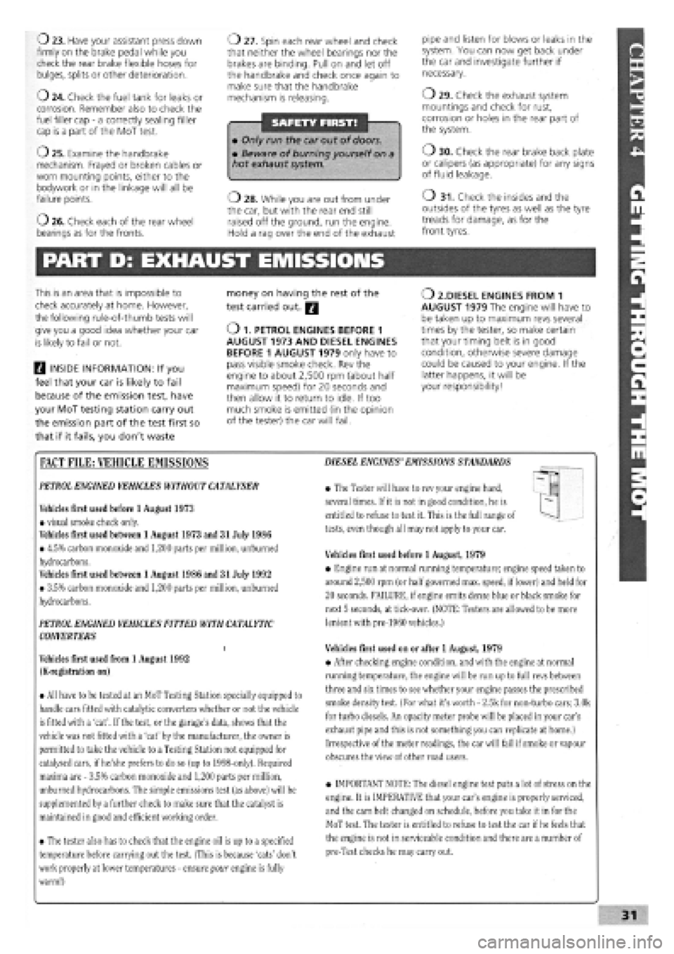
o 28. While you are out from under the car, but with the rear end still raised off the ground, run the engine. Hold a rag over the end of the exhaust
pipe and listen for blows or leaks in the system. You can now get back under the car and investigate further if necessary.
o 29. Check the exhaust system mountings and check for rust, corrosion or holes in the rear part of the system.
o 30. Check the rear brake back plate or calipers (as appropriate) for any signs of fluid leakage.
o 31. Check the insides and the outsides of the tyres as well as the tyre treads for damage, as for the front tyres.
PART D: EXHAUST EMISSIONS
This is an area that is impossible to
check accurately at home. However,
the following rule-of-thumb tests will
give you a good idea whether your car
is likely to fail or not.
H INSIDE INFORMATION: If you
feel that your car is likely to fail
because of the emission test, have
your MoT testing station carry out
the emission part of the test first so
that if it fails, you don't waste
money on having the rest of the
test carried out. Q
O 1. PETROL ENGINES BEFORE 1 AUGUST 1973 AND DIESEL ENGINES BEFORE 1 AUGUST 1979 only have to pass visible smoke check. Rev the engine to about 2,500 rpm (about half maximum speed) for 20 seconds and then allow it to return to idle. If too much smoke is emitted (in the opinion of the tester) the car will fail.
O 2.DIESEL ENGINES FROM 1 AUGUST 1979 The engine will have to be taken up to maximum revs several times by the tester, so make certain that your timing belt is in good condition, otherwise severe damage could be caused to your engine. If the latter happens, it will be your responsibility!
FACT FILE: VEHICLE EMISSIONS
PETROL
ENGINED VEHICLES WITHOUT
CATALYSER
Vehicles first used before 1 August 1973
• visual smoke check only.
Vehicles first used between 1 August 1973 and 31 July 1986
• 4.5% carbon monoxide and 1,200 parts per million, unburned
hydrocarbons.
Vehicles first used between 1 August 1986 and 31 July 1992
• 3.5% carbon monoxide and 1,200 parts per million, unburned
hydrocarbons.
PETROL ENGINED VEHICLES FITTED WITH
CATALYTIC
CONVERTERS
i
Vehicles first used from 1 August 1992
(K-registration on)
• All have to be tested at an MoT Testing Station specially equipped to
handle cars fitted with catalytic converters whether or not the vehicle
is fitted with a 'cat'. If
the
test, or the garage's data, shows that the
vehicle was not fitted with a 'cat' by the manufacturer, the owner is
permitted to take the vehicle to
a
Testing Station not equipped for
catalysed cars, if he/she prefers to do so (up to 1998-only). Required
maxima are
-
3.5% carbon monoxide and 1,200 parts per million,
unburned hydrocarbons. The simple emissions test (as above) will be
supplemented by a further check to make sure that the catalyst is
maintained in
good
and efficient working order.
• The tester also has to check that the engine oil is up to a specified
temperature before carrying out the test. (This is because 'cats' don't
work properly at lower temperatures
-
ensure your engine is fully
warm!)
DIESEL ENGINES'EMISSIONS
STANDARDS
• The Tester will have to rev your engine hard,
several times. If it is not in good condition, he is
entitled to refuse to test it. This is the full range of
tests, even though all may not apply to your car.
Vehicles first used before 1 August, 1979
• Engine run at normal running temperature; engine speed taken to
around 2,500 rpm (or half
governed
max. speed, if lower) and held for
20 seconds. FAILURE, if engine emits dense blue or black smoke for
next 5 seconds, at tick-over. (NOTE: Testers are allowed to be more
lenient with pre-1960 vehicles.)
Vehicles first used on or after 1 August, 1979
• After checking engine condition, and with the engine at normal
running temperature, the engine will be run up to full revs between
three and six times to see whether your engine passes the prescribed
smoke density test. (For what it's worth
-
2.5k for non-turbo cars; 3.0k
for turbo diesels. An opacity meter probe will be placed in your car's
exhaust pipe and this is not something you can replicate at home.)
Irrespective of the meter readings, the car will fail if
smoke
or vapour
obscures the view of other road users.
• IMPORTANT NOTE: The diesel engine test puts a lot of stress on the
engine. It is IMPERATIVE that your car's engine is properly serviced,
and the cam belt changed on schedule, before you take it in for the
MoT test. The tester is entitled to refuse to test the car if
he
feels that
the engine is not in serviceable condition and there are a number of
pre-Test checks he may carry out.
Page 30 of 171
PART G: BRAKING SYSTEM
Job 49. Check front brakes
Job 50. Check rear brakes
Job 51. Check/adjust handbrake
Job 52. Check brake pipes
Job 53. Change brake hydraulic fluid
SERVICE INTERVALS
C
C
C
C
E
Job 56. Check seat and seat belt mountings C
Job 57. Check headlight alignment C
Job 58. Check underbody C
Job 59. Check spare tyre B
Job 60. Change pollen filter C
Job 61. Replace airbag gas generator 10 years
PART I: ROAD TEST
PART H: BODYWORK & INTERIOR
Job 54. Lubricate hinges and locks
Job 55. Check windscreen
Job 62. Road test and specialist check. AFTER EVERY
SERVICE
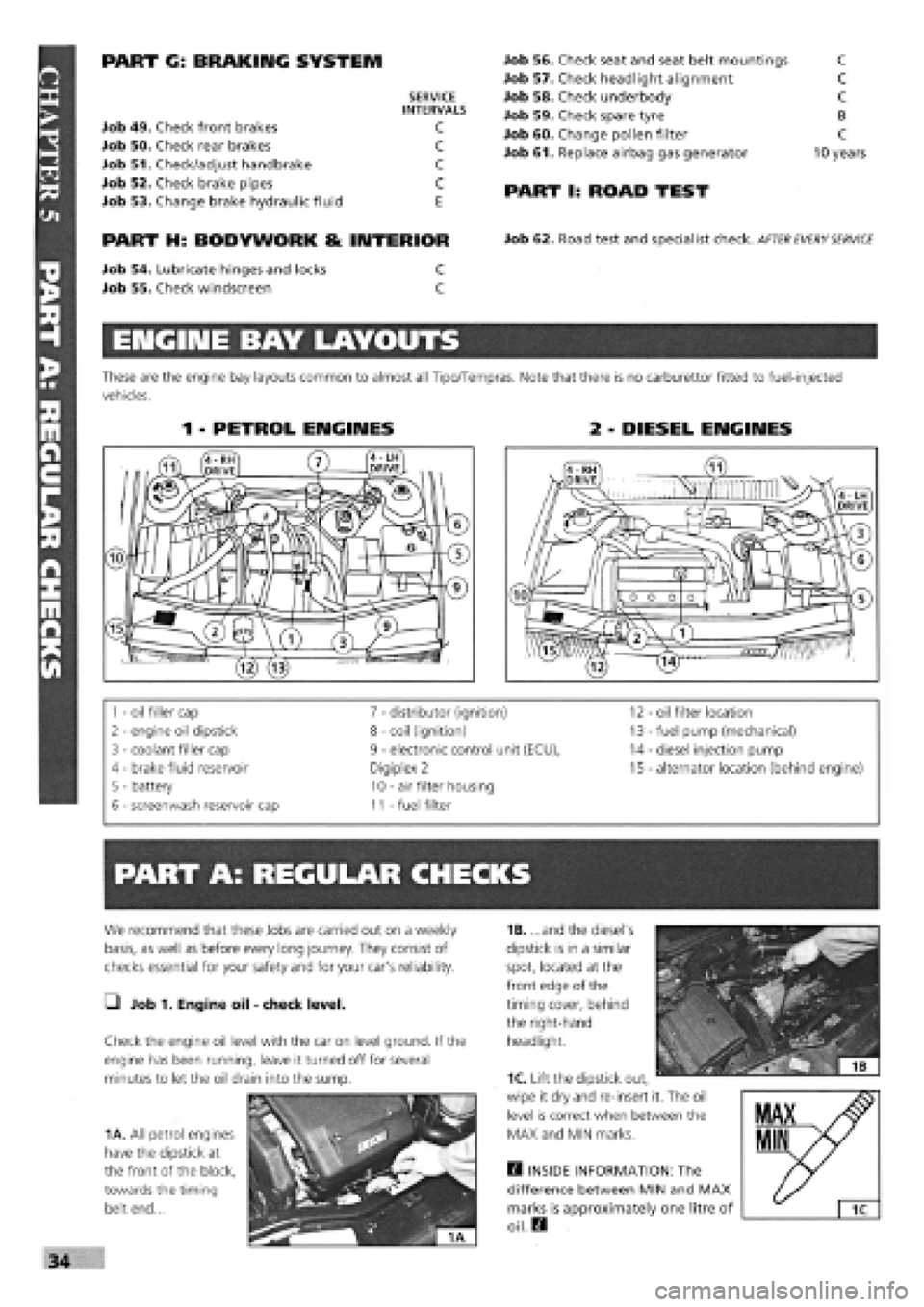
ENGINE BAY LAYOUTS
These are the engine bay layouts common to almost all Tipo/Tempras. Note that there is no carburettor fitted to fuel-injected
vehicles.
1 - PETROL ENGINES 2 - DIESEL ENGINES
1
-
oil filler cap 7
-
distributor (ignition) 12 - oil filter location
2
-
engine oil dipstick 8
-
coil (ignition) 13
-
fuel pump (mechanical)
3
-
coolant filler cap 9
-
electronic control unit (ECU), 14
-
diesel injection pump
4 - brake fluid reservoir Digiplex 2 15
-
alternator location (behind engine)
5 - battery 10
-
air filter housing
6
-
screenwash reservoir cap 11
-
fuel filter
PART A: REGULAR CHECKS
1B. ...and the diesel's
dipstick is in a similar
spot, located at the
front edge of the
timing cover, behind
the right-hand
headlight.
Q INSIDE INFORMATION: The
difference between MIN and MAX
marks is approximately one litre of
oil. Q
We recommend that these Jobs are carried out on a weekly
basis, as well as before every long journey. They consist of
checks essential for your safety and for your car's reliability.
• Job 1. Engine oil
-
check level.
Check the engine oil level with the car on level ground. If the
engine has been running, leave it turned off for several
minutes to let the oil drain into the sump.
1A. All petrol engines
have the dipstick at
the front of the block,
towards the timing
belt end...
1C. Lift the dipstick out,
wipe it dry and re-insert it. The oil
level is correct when between the
MAX and MIN marks.
Page 53 of 171
PART F: STEERING AMD SUSPENSION
G Job 42. Check front wheel bearings.
In
order to check for wear:
• raise the front of the car on axle stands (see Chapter 1,
Safety First!)
• place the gearbox in neutral
• pull the handbrake securely on and chock the rear wheels
Try
spinning each wheel (as far as possible with a front-drive
car), feeling for rough rotation. Rock the wheel about its
centre, feeling for excess bearing play.
D INSIDE INFORMATION: If a wheel bearing is worn, you
will normally hear a noise on the outer, loaded bearing
when cornering. D
G Job 43. Check front suspension.
BOTTOM BALL JOINT
Jack
up
the car underneath the suspension lower arm
(wishbone), so that the wheel is two inches off the ground.
See Chapter
1,
Safety First.
SUSPENSION STRUT/SHOCK ABSORBER
43D. Examine the shock
absorber, which is enclosed
inside the coil spring, for
leaks, looking for signs of a
'damp' oil stain seeping from
underneath the top half of
the shock absorber body.
The top of the strut/shock
absorber is mounted in a
rubber bush which can be
checked for softness,
cracking or deterioration
from inside the engine bay.
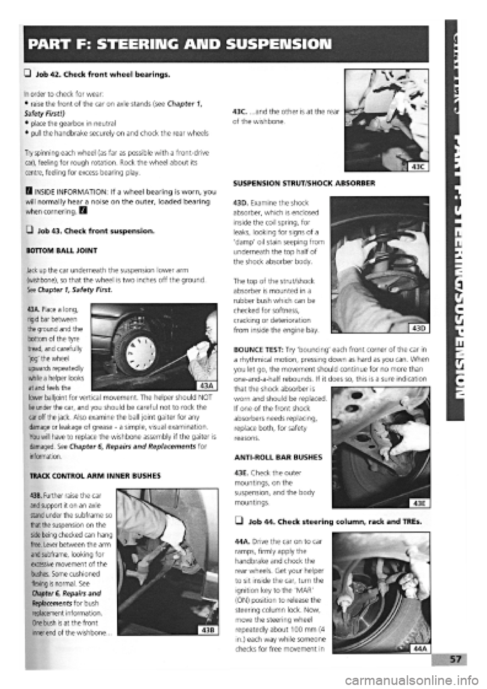
43A. Place a long,
rigid bar between
the
ground and the
bottom of the tyre
tread, and carefully
'jog' the wheel
upwards repeatedly
while a helper looks
at and
feels the
lower balljoint for vertical movement. The helper should NOT
lie
under the car, and you should be careful not to rock the
car
off
the jack.
Also examine the ball joint gaiter for any
damage
or leakage of grease
-
a simple, visual examination.
You will
have to replace the wishbone assembly if the gaiter is
damaged. See Chapter
6,
Repairs and Replacements for
information.
TRACK CONTROL ARM INNER BUSHES
43B. Further raise the car
and
support it on an axle
stand
under the subframe so
that the
suspension on the
side being
checked can hang
free. Lever between the arm
and
subframe, looking for
excessive movement of the
bushes. Some cushioned
flexing
is
normal. See
Chapter
6, Repairs and
Replacements for bush
replacement information.
One bush is
at the front
inner end
of the wishbone...
ANTI-ROLL BAR BUSHES
43E. Check the outer
mountings, on the
suspension, and the body
mountings.
• Job 44. Check steering column, rack and TREs.
44A. Drive the car on to car
ramps, firmly apply the
handbrake and chock the
rear wheels. Get your helper
to sit inside the car, turn the
ignition key to the 'MAR'
(ON) position to release the
steering column lock. Now,
move the steering wheel
repeatedly about 100 mm (4
in.) each way while someone
checks for free movement in
BOUNCE TEST: Try 'bouncing' each front corner of the car in
a rhythmical motion, pressing down as hard as you can. When
you let go, the movement should continue for no more than
one-and-a-half rebounds. If it does so, this is a sure indication
that the shock absorber is
worn and should be replaced.
If one of the front shock
absorbers needs replacing,
replace both, for safety
reasons.
Page 54 of 171
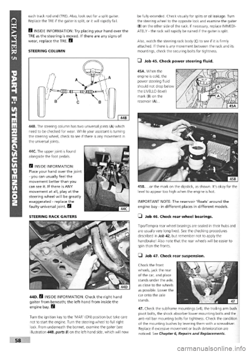
each track rod end (TRE). Also, look out for a split gaiter.
Replace the TRE if the gaiter is split, or it will rapidly fail.
E3 INSIDE INFORMATION: Try placing your hand over the
TRE as the steering is moved. If there are any signs of
wear, replace the TRE. Q
STEERING COLUMN
44B. The steering column has two universal joints (A) which
need to be checked for wear. While your assistant is turning
the steering wheel, check to see if there is any movement in
the universal joints.
44C. The upper joint is found
alongside the foot pedals.
Q INSIDE INFORMATION:
Place your hand over the joint
-
you can usually feel the
movement better than you
can see it. If there is ANY
movement at all, play at the
steering wheel will be greatly
exaggerated
-
replace the
faulty universal joint. B
STEERING RACK GAITERS
44D. B INSIDE INFORMATION: Check the right hand
gaiter from beneath; the left-hand from inside the
engine bay. Q
Turn the ignition key to the 'MAR' (ON) position but take care
not to start the engine. Turn the steering wheel to full right
lock. From underneath the bonnet, examine the gaiter (see
illustration 44B, parts B) on the left-hand side, which will now
be fully extended. Check visually for splits or oil leakage. Turn
the steering wheel to the opposite lock and examine the gaiter
(B) on the other side of the rack. If necessary, replace IMMEDI-
ATELY
-
the rack will rapidly be ruined if the gaiter is split.
Also, watch the steering rack body (C) to see if it is firmly
attached. If there is any movement between the rack and its
mountings, check the securing bolts for tightness.
• Job 45. Check power steering fluid.
45A. When the
engine is cold, the
power steering fluid
should not drop below
the LIVELLO (level)
mark (B) on the
reservoir (A)...
45B. ...or the mark on the dipstick, as shown. It's okay for the
level to appear too high when the engine is hot.
IMPORTANT NOTE: The reservoir 'floats' around the
engine bay
-
in different places in different models.
• Job 46. Check rear wheel bearings.
Tipo/Tempra rear wheel bearings are sealed in their hubs and
are usually very long lived. See the checking procedures
described in Job 42, but remember not to apply the
handbrake! Also note that the rear wheels will be easier to
spin than the fronts.
• Job 47. Check rear suspension.
Chock the front
wheels, jack the rear
of the car, and place
stands under the axle,
as close to the wheels
as possible. Lower the
car onto the axle
stands.
47. Check the subframe mountings (x4), the trailing arm bush
pivot bolts, the shock absorber lower mounting bolts and the
anti-roll bar mounting bolts for tightness. Check the condition
of the mounting bushes by levering them with a screwdriver.
Replace if excessive movement or bush deterioration are
noticed. See Chapter
6,
Repairs and Replacements.
Page 56 of 171
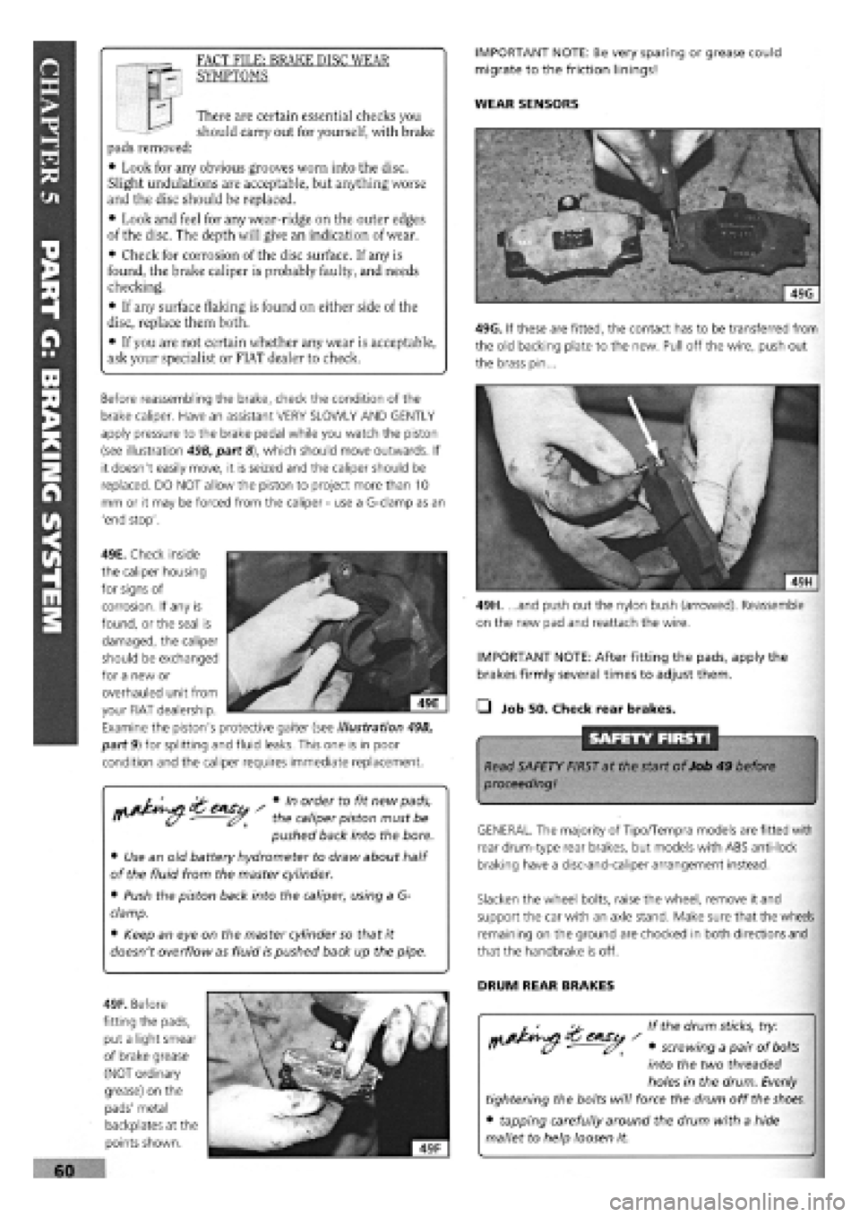
49H. ...and push out the nylon bush (arrowed). Reassemble
on the new pad and reattach the wire.
IMPORTANT NOTE: After fitting the pads, apply the
brakes firmly several times to adjust them.
• Job 50. Check rear brakes.
SAFETY FIRST!
Read SAFETY FIRST at the start of Job 49 before
proceeding!
GENERAL. The majority of Tipo/Tempra models are fitted with
rear drum-type rear brakes, but models with ABS anti-lock
braking have a disc-and-caliper arrangement instead.
Slacken the wheel bolts, raise the wheel, remove it and
support the car with an axle stand. Make sure that the wheels
remaining on the ground are chocked in both directions and
that the handbrake is off.
DRUM REAR BRAKES
If the drum
sticks,
try:
• screwing a pair of
bolts
into the two threaded
holes in the drum. Evenly
tightening the bolts will force the drum off the
shoes.
• tapping carefully around the drum with a hide
mallet to help loosen it.
s Vn order to fit new pads,
r> - the caliper piston must be
pushed back into the bore.
• Use an old battery hydrometer to draw about half
of the fluid from the master cylinder.
• Push the piston back into the caliper, using a G-
clamp.
• Keep an eye on the master cylinder so that it
doesn't overflow as fluid is pushed back up the pipe.
IMPORTANT NOTE: Be very sparing or grease could
migrate to the friction linings!
WEAR SENSORS I I There are certain essential checks you
should carry out for yourself, with brake
pads removed:
• Look for any obvious grooves worn into the disc.
Slight undulations are acceptable, but anything worse
and the disc should be replaced.
• Look and feel for any wear-ridge on the outer edges
of the disc. The depth will give an indication of wear.
• Check for corrosion of the disc surface. If any is
found, the brake caliper is probably faulty, and needs
checking.
• If any surface flaking is found on either side of the
disc, replace them both.
• If you are not certain whether any wear is acceptable,
ask your specialist or FIAT dealer to check.
FACT FILE: BRAKE DISC WEAR
SYMPTOMS
Before reassembling the brake, check the condition of the
brake caliper. Have an assistant VERY SLOWLY AND GENTLY
apply pressure to the brake pedal while you watch the piston
(see illustration 49B, part
8),
which should move outwards. If
it doesn't easily move, it is seized and the caliper should be
replaced. DO NOT allow the piston to project more than 10
mm or it may be forced from the caliper
-
use a G-clamp as an
'end stop'.
49F. Before
fitting the pads,
put a light smear
of brake grease
(NOT ordinary
grease) on the
pads' metal
backplates at the
points shown.
49G. If these are fitted, the contact has to be transferred from
the old backing plate to the new. Pull off the wire, push out
the brass pin...
49E. Check inside
the caliper housing
for signs of
corrosion. If any is
found, or the seal is
damaged, the caliper
should be exchanged
for a new or
overhauled unit from
your FIAT dealership.
Examine the piston's protective gaiter (see illustration 49B,
part 9) for splitting and fluid leaks. This one is in poor
condition and the caliper requires immediate replacement.