headlights FIAT TIPO 5DOORS STATION WAGON 2018 Owner handbook (in English)
[x] Cancel search | Manufacturer: FIAT, Model Year: 2018, Model line: TIPO 5DOORS STATION WAGON, Model: FIAT TIPO 5DOORS STATION WAGON 2018Pages: 292, PDF Size: 7.74 MB
Page 85 of 292
WARNING
62)The system is an aid for the driver, who
must always pay full attention while driving.
The responsibility always rests with the
driver, who must take into account the
traffic conditions in order to drive in
complete safety. The driver must always
maintain a safe distance from the vehicle in
front.
63)If the driver depresses the brake pedal
fully or carries out a fast steering during
system operation, the automatic braking
function may stop (e.g. to allow a possible
manoeuvre to avoid the obstacle).
64)The system intervenes on vehicles
travelling in the same lane. People, animals
and things (e.g. pushchairs) are not taken
into consideration.
65)If the car must be placed on a roller
bench for maintenance interventions or if it
is washed in an automatic roller washing
tunnel with an obstacle in the front part
(e.g. another car, a wall or another
obstacle), the system may detect its
presence and activate. In this case the
system must be deactivated through the
settings of theUconnect™5"or7" HD
system.
66)If the iTMPS system signals a pressure
decrease on the tyres, it is recommended
to check the pressure on all four tyres.
67)The iTPMS does not relieve the driver
from the obligation to check the tyre
pressure every month; it is not even to be
considered a replacing system for
maintenance or a safety system.68)Tyre pressure must be checked with
tyres cold. Should it become necessary for
whatever reason to check pressure with
warm tyres, do not reduce pressure even
though it is higher than the prescribed
value, but repeat the check when tyres are
cold
69)The iTPMS cannot indicate sudden tyre
pressure drops (e.g. if a tyre bursts). In this
case, stop the vehicle, braking with caution
and avoiding abrupt steering.
70)The system only warns that the tyre
pressure is low: it is not able to inflate
them.
71)Insufficient tyre inflation increases fuel
consumption, reduces the tread duration
and may affect the capacity to drive safely.
IMPORTANT
28)The system may have limited or absent
operation due to weather conditions such
as: heavy rain, hail, thick fog, heavy snow.
29)The section of the bumper before the
sensor must not be covered with
adhesives, auxiliary headlights or any other
object.
30)System intervention might be
unexpected or delayed when other vehicles
transport loads projecting from the side,
above or from the rear, with respect to the
normal size of the vehicle.
31)Operation can be adversely affected by
any structural change made to the vehicle,
such as a modification to the front
geometry, tyre change, or a heavier load
than the standard load of the vehicle.32)Incorrect repairs made on the front part
of the vehicle (e.g. bumper, chassis) may
alter the position of the radar sensor, and
adversely affect its operation. Go to a Fiat
Dealership for any operation of this type.
33)Do not tamper nor operate on the radar
sensor. In the event of a sensor failure,
contact a Fiat Dealership.
34)When towing a trailer (with modules
installed after purchasing the vehicle), a
vehicle or during loading manoeuvres on a
vehicle transporter (or in vehicle for
transport), the system must be deactivated
via theUconnect™5"or7" HDsystem.
35)Do not wash with high-pressure jets in
the bumper lower area: in particular do not
operate on the system's electrical
connector.
36)Be careful in the case of repairs and
new paintings in the area around the
sensor (panel covering the sensor on the
left side of the bumper). In the event of a
frontal impact the sensor may automatically
deactivate and display a warning to indicate
that the sensor needs to be repaired. Even
without a malfunction warning, deactivate
the system operation if you think that the
position of the radar sensor has changed
(e.g. due to low-speed frontal impact as
during parking manoeuvres). In these
cases, go to a Fiat Dealership to have the
radar sensor realigned or replaced.
83
Page 130 of 292
ELECTRONIC CRUISE
CONTROL MODE
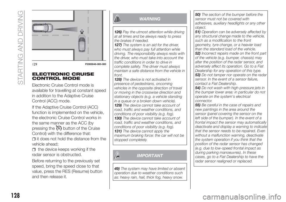
Electronic Cruise Control mode is
available for travelling at constant speed
in addition to the Adaptive Cruise
Control (ACC) mode.
If the Adaptive Cruise Control (ACC)
function is implemented on the vehicle,
the electronic Cruise Control works in
the same manner as the ACC (by
pressing the
button of the Cruise
Control) with the difference that:
it does not hold the distance from the
vehicle ahead;
the device keeps working if the
radar sensor is obstructed.
Before returning to the previously set
speed, bring the speed close to that
value, press the RES (Resume) button
and then release it.
WARNING
126)Pay the utmost attention while driving
at all times and be always ready to press
the brakes if needed.
127)The system is an aid for the driver,
who must always pay full attention while
driving. The responsibility always rests with
the driver, who must take into account the
traffic conditions in order to drive in
complete safety. The driver must always
maintain a safe distance from the vehicle in
front.
128)The device is not activated in
presence of pedestrians, oncoming
vehicles in the opposite direction of travel
or moving in the crosswise direction and
stationary objects (e.g. a vehicle standing
in a queue or a broken down vehicle).
129)The device cannot take account of
road, traffic and weather conditions, and
conditions of poor visibility (e.g. fog).
130)The device cannot take account of
road, traffic and weather conditions, and
conditions of poor visibility (e.g. fog).
131)The device cannot apply the
maximum braking force: the car will not be
stopped completely.
IMPORTANT
49)The system may have limited or absent
operation due to weather conditions such
as: heavy rain, hail, thick fog, heavy snow.50)The section of the bumper before the
sensor must not be covered with
adhesives, auxiliary headlights or any other
object.
51)Operation can be adversely affected by
any structural change made to the vehicle,
such as a modification to the front
geometry, tyre change, or a heavier load
than the standard load of the vehicle.
52)Incorrect repairs made on the front part
of the vehicle (e.g. bumper, chassis) may
alter the position of the radar sensor, and
adversely affect its operation. Go to a Fiat
Dealership for any operation of this type.
53)Do not tamper nor operate on the radar
sensor. In the event of a sensor failure,
contact a Fiat Dealership.
54)Do not wash with high-pressure jets in
the bumper lower area: in particular do not
operate on the system's electrical
connector.
55)Be careful in the case of repairs and
new paintings in the area around the
sensor (panel covering the sensor on the
left side of the bumper). In the event of a
frontal impact the sensor may automatically
deactivate and display a warning to indicate
that the sensor needs to be repaired. Even
without a malfunction warning, deactivate
the system operation if you think that the
position of the radar sensor has changed
(e.g. due to low-speed frontal impact as
during parking manoeuvres). In these
cases, go to a Fiat Dealership to have the
radar sensor realigned or replaced.
129P2000046-000-000
128
STARTING AND DRIVING
Page 141 of 292
HAZARD WARNING
LIGHTS
CONTROL
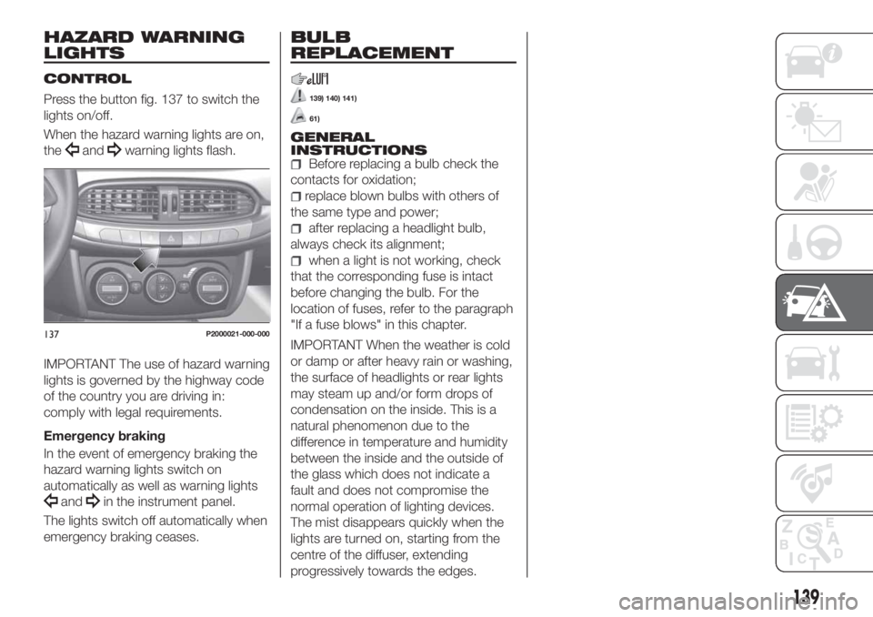
Press the button fig. 137 to switch the
lights on/off.
When the hazard warning lights are on,
the
andwarning lights flash.
IMPORTANT The use of hazard warning
lights is governed by the highway code
of the country you are driving in:
comply with legal requirements.
Emergency braking
In the event of emergency braking the
hazard warning lights switch on
automatically as well as warning lights
andin the instrument panel.
The lights switch off automatically when
emergency braking ceases.
BULB
REPLACEMENT
139) 140) 141)
61)
GENERAL
INSTRUCTIONS
Before replacing a bulb check the
contacts for oxidation;
replace blown bulbs with others of
the same type and power;
after replacing a headlight bulb,
always check its alignment;
when a light is not working, check
that the corresponding fuse is intact
before changing the bulb. For the
location of fuses, refer to the paragraph
"If a fuse blows" in this chapter.
IMPORTANT When the weather is cold
or damp or after heavy rain or washing,
the surface of headlights or rear lights
may steam up and/or form drops of
condensation on the inside. This is a
natural phenomenon due to the
difference in temperature and humidity
between the inside and the outside of
the glass which does not indicate a
fault and does not compromise the
normal operation of lighting devices.
The mist disappears quickly when the
lights are turned on, starting from the
centre of the diffuser, extending
progressively towards the edges.137P2000021-000-000
139
Page 143 of 292
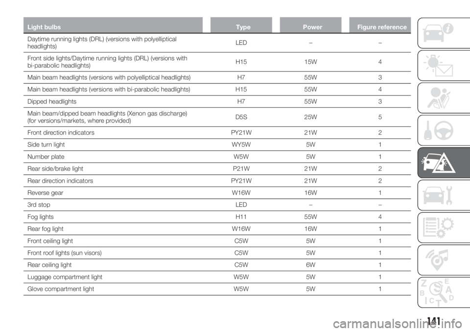
Light bulbs Type Power Figure reference
Daytime running lights (DRL) (versions with polyelliptical
headlights)LED – –
Front side lights/Daytime running lights (DRL) (versions with
bi-parabolic headlights)H15 15W 4
Main beam headlights (versions with polyelliptical headlights) H7 55W 3
Main beam headlights (versions with bi-parabolic headlights) H15 55W 4
Dipped headlights H7 55W 3
Main beam/dipped beam headlights (Xenon gas discharge)
(for versions/markets, where provided)D5S 25W 5
Front direction indicators PY21W 21W 2
Side turn light WY5W 5W 1
Number plate W5W 5W 1
Rear side/brake light P21W 21W 2
Rear direction indicators PY21W 21W 2
Reverse gear W16W 16W 1
3rd stop LED – –
Fog lights H11 55W 4
Rear fog light W16W 16W 1
Front ceiling light C5W 5W 1
Front roof lights (sun visors) C5W 5W 1
Rear ceiling light C5W 6W 1
Luggage compartment light W5W 5W 1
Glove compartment light W5W 5W 1
141
Page 144 of 292
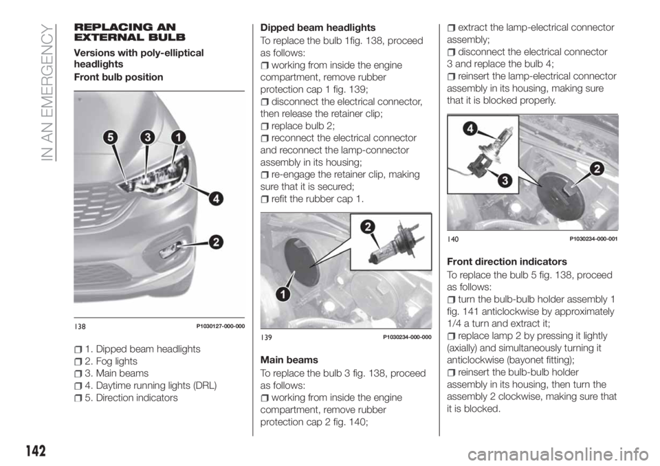
REPLACING AN
EXTERNAL BULB
Versions with poly-elliptical
headlights
Front bulb position
1. Dipped beam headlights
2. Fog lights
3. Main beams
4. Daytime running lights (DRL)
5. Direction indicatorsDipped beam headlights
To replace the bulb 1fig. 138, proceed
as follows:
working from inside the engine
compartment, remove rubber
protection cap 1 fig. 139;
disconnect the electrical connector,
then release the retainer clip;
replace bulb 2;
reconnect the electrical connector
and reconnect the lamp-connector
assembly in its housing;
re-engage the retainer clip, making
sure that it is secured;
refit the rubber cap 1.
Main beams
To replace the bulb 3 fig. 138, proceed
as follows:
working from inside the engine
compartment, remove rubber
protection cap 2 fig. 140;
extract the lamp-electrical connector
assembly;
disconnect the electrical connector
3 and replace the bulb 4;
reinsert the lamp-electrical connector
assembly in its housing, making sure
that it is blocked properly.
Front direction indicators
To replace the bulb 5 fig. 138, proceed
as follows:
turn the bulb-bulb holder assembly 1
fig. 141 anticlockwise by approximately
1/4 a turn and extract it;
replace lamp 2 by pressing it lightly
(axially) and simultaneously turning it
anticlockwise (bayonet fitting);
reinsert the bulb-bulb holder
assembly in its housing, then turn the
assembly 2 clockwise, making sure that
it is blocked.
138P1030127-000-000
139P1030234-000-000
140P1030234-000-001
142
IN AN EMERGENCY
Page 145 of 292

Front fog lamps
To replace the bulb 2 fig. 138, proceed
as follows:
steer the car wheels inwards;
undo screw 1 fig. 142 using the
screwdriver provided and remove
inspection flap 2;
turn the bulb-bulb holder assembly
3 anticlockwise by a 1/4 turn and
extract it;
disconnect the electrical connector
and replace the complete assembly;
reconnect the electrical connector to
the new bulb-bulb holder assembly;
fit the assembly in its housing,
turning it clockwise and making sure
that it is blocked properly;
finally, refit the inspection flap 1.
Daytime running lights (DRL)
The daytime running light bulbs 4
fig. 138 are LED to increase their
lifetime; therefore, they should not
require replacing. Contact the Fiat
Dealership in the event of any kind of
problem.
Side turn light
To replace the bulb, proceed as follows:
press the lens 1 fig. 143 to compress
in the internal clip 2, then pull the
cluster outwards; take great care not
damage the paintwork;;
turn the bulb holder 2 anticlockwise,
then extract the press-fit bulb 3 and
replace it;
refit the bulb holder 2 in the lens
1 and turn it clockwise;
refit the cluster making sure that the
internal clip clicks into position.Versions with bi-parabolic
headlights
Front bulb position
1. Dipped headlights
2. Fog lights
3. Main beam headlights / Daytime
running lights (DRL)/ Positions
4. Direction indicator.
141P2000185
142P2000135
143P1030251-000-000
14408026J0002EM
143
Page 146 of 292
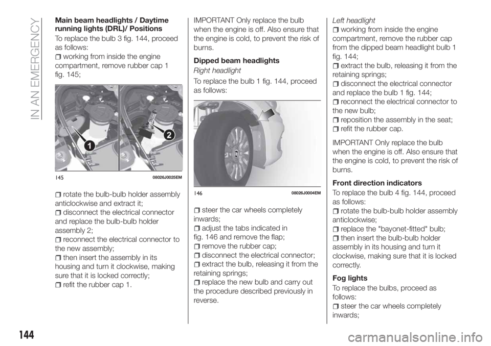
Main beam headlights / Daytime
running lights (DRL)/ Positions
To replace the bulb 3 fig. 144, proceed
as follows:
working from inside the engine
compartment, remove rubber cap 1
fig. 145;
rotate the bulb-bulb holder assembly
anticlockwise and extract it;
disconnect the electrical connector
and replace the bulb-bulb holder
assembly 2;
reconnect the electrical connector to
the new assembly;
then insert the assembly in its
housing and turn it clockwise, making
sure that it is locked correctly;
refit the rubber cap 1.
IMPORTANT Only replace the bulb
when the engine is off. Also ensure that
the engine is cold, to prevent the risk of
burns.
Dipped beam headlights
Right headlight
To replace the bulb 1 fig. 144, proceed
as follows:
steer the car wheels completely
inwards;
adjust the tabs indicated in
fig. 146 and remove the flap;
remove the rubber cap;
disconnect the electrical connector;
extract the bulb, releasing it from the
retaining springs;
replace the new bulb and carry out
the procedure described previously in
reverse.Left headlight
working from inside the engine
compartment, remove the rubber cap
from the dipped beam headlight bulb 1
fig. 144;
extract the bulb, releasing it from the
retaining springs;
disconnect the electrical connector
and replace the bulb 1 fig. 144;
reconnect the electrical connector to
the new bulb;
reposition the assembly in the seat;
refit the rubber cap.
IMPORTANT Only replace the bulb
when the engine is off. Also ensure that
the engine is cold, to prevent the risk of
burns.
Front direction indicators
To replace the bulb 4 fig. 144, proceed
as follows:
rotate the bulb-bulb holder assembly
anticlockwise;
replace the "bayonet-fitted" bulb;
then insert the bulb-bulb holder
assembly in its housing and turn it
clockwise, making sure that it is locked
correctly.
Fog lights
To replace the bulbs, proceed as
follows:
steer the car wheels completely
inwards;
14508026J0025EM
14608026J0004EM
144
IN AN EMERGENCY
Page 147 of 292
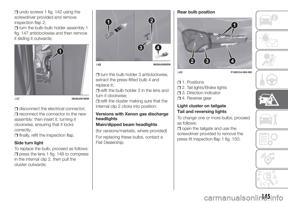
undo screws 1 fig. 142 using the
screwdriver provided and remove
inspection flap 2;
turn the bulb-bulb holder assembly 1
fig. 147 anticlockwise and then remove
it sliding it outwards;
disconnect the electrical connector;
reconnect the connector to the new
assembly: then insert it, turning it
clockwise, ensuring that it locks
correctly;
finally, refit the inspection flap.
Side turn light
To replace the bulb, proceed as follows:
press the lens 1 fig. 148 to compress
in the internal clip 2, then pull the
cluster outwards;
turn the bulb holder 3 anticlockwise,
extract the press-fitted bulb 4 and
replace it;
refit the bulb holder 3 in the lens and
turn it clockwise;
refit the cluster making sure that the
internal clip 2 clicks into position.
Versions with Xenon gas discharge
headlights
Main/dipped beam headlights
(for versions/markets, where provided)
For replacing these bulbs, contact a
Fiat Dealership.Rear bulb position
1. Positions
2. Tail lights/Brake lights
3. Direction indicator
4. Reverse gear
Light cluster on tailgate
Tail and reversing lights
To change one or more bulbs, proceed
as follows:
open the tailgate and use the
screwdriver provided to remove the
press-fit inspection flap 1 fig. 150;
14708026J0016EM
14808026J0005EM
149P1030154-000-000
145
Page 175 of 292
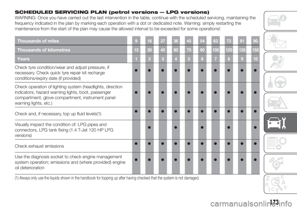
SCHEDULED SERVICING PLAN (petrol versions — LPG versions)
WARNING: Once you have carried out the last intervention in the table, continue with the scheduled servicing, maintaining the
frequency indicated in the plan by marking each operation with a dot or dedicated note. Warning: simply restarting the
maintenance from the start of the plan may cause the allowed interval to be exceeded for some operations!
Thousands of miles9 182736455463728190
Thousands of kilometres15 30 45 60 75 90 105 120 135 150
Years12345678910
Check tyre condition/wear and adjust pressure, if
necessary. Check quick tyre repair kit recharge
conditions/expiry date (if provided)
Check operation of lighting system (headlights, direction
indicators, hazard warning lights, boot, passenger
compartment, glove compartment, instrument panel
warning lights, etc.)
Check and, if necessary, top up fluid levels(1)
Visually inspect the condition of: LPG pipes and
connectors, LPG tank fixing (1.4 T-Jet 120 HP LPG
versions)
Check exhaust emissions
Use the diagnosis socket to check engine management
system operation; emissions and (where provided) engine
oil deterioration
(1) Always only use the liquids shown in the handbook for topping up after having checked that the system is not damaged.
173
Page 181 of 292
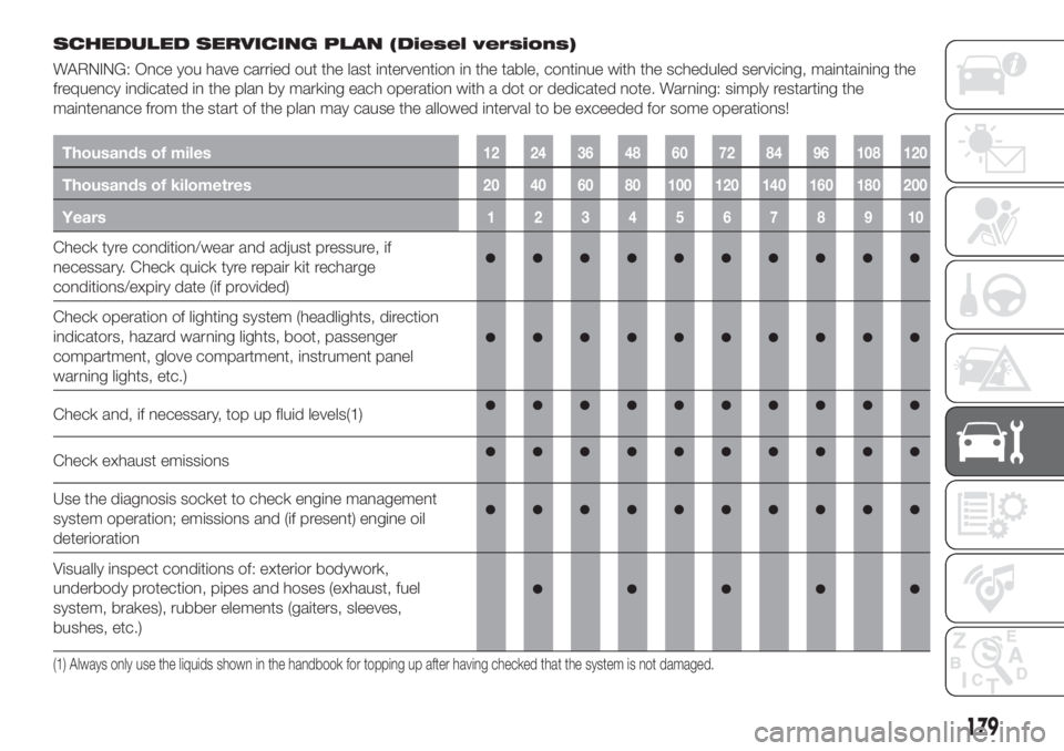
SCHEDULED SERVICING PLAN (Diesel versions)
WARNING: Once you have carried out the last intervention in the table, continue with the scheduled servicing, maintaining the
frequency indicated in the plan by marking each operation with a dot or dedicated note. Warning: simply restarting the
maintenance from the start of the plan may cause the allowed interval to be exceeded for some operations!
Thousands of miles12 24 36 48 60 72 84 96 108 120
Thousands of kilometres20 40 60 80 100 120 140 160 180 200
Years12345678910
Check tyre condition/wear and adjust pressure, if
necessary. Check quick tyre repair kit recharge
conditions/expiry date (if provided)
Check operation of lighting system (headlights, direction
indicators, hazard warning lights, boot, passenger
compartment, glove compartment, instrument panel
warning lights, etc.)
Check and, if necessary, top up fluid levels(1)
Check exhaust emissions
Use the diagnosis socket to check engine management
system operation; emissions and (if present) engine oil
deterioration
Visually inspect conditions of: exterior bodywork,
underbody protection, pipes and hoses (exhaust, fuel
system, brakes), rubber elements (gaiters, sleeves,
bushes, etc.)
(1) Always only use the liquids shown in the handbook for topping up after having checked that the system is not damaged.
179