clock FIAT TIPO 5DOORS STATION WAGON 2018 Owner handbook (in English)
[x] Cancel search | Manufacturer: FIAT, Model Year: 2018, Model line: TIPO 5DOORS STATION WAGON, Model: FIAT TIPO 5DOORS STATION WAGON 2018Pages: 292, PDF Size: 7.74 MB
Page 14 of 292
use a coin to rotate the inspection lid
2 anticlockwise and remove it;
replace battery 3 with a new one
that has the same specifications,
respect polarity;
refit lid 2 rotating it clockwise, then
reclose the rear casing by pressing
gently and make sure it is correctly
locked.
REQUEST FOR
ADDITIONAL KEYS
Key with remote control
The system can recognise up to 8 keys
with remote control.
Duplicating keys
Should a new key with remote control
be necessary, go to a Fiat Dealership,
taking an ID document and the car
ownership documents.
WARNING
1)Press button 2 only with the key away
from your body, especially your eyes and
from objects which could get damaged
(e.g. your clothes). Do not leave the key
unattended to avoid the button being
accidentally pressed while it is being
handled, e.g. by a child.
IMPORTANT
1)The electronic components inside the
key may be damaged if the key is subjected
to strong shocks. In order to ensure
complete efficiency of the electronic
devices inside the key, it should never be
exposed to direct sunlight.
IMPORTANT
1)Used batteries may be harmful to the
environment if not disposed of correctly.
They must be disposed of as specified by
law in the special containers or taken to a
Fiat Dealership, which will take care of their
disposal.
IGNITION DEVICE
OPERATION
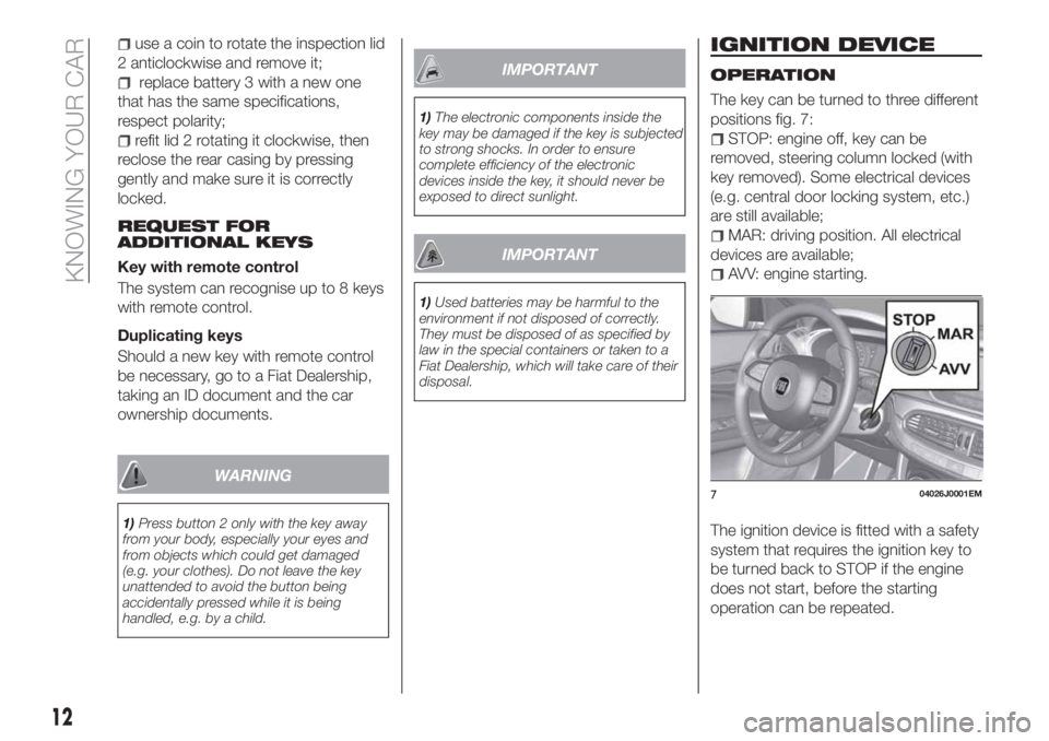
The key can be turned to three different
positions fig. 7:
STOP: engine off, key can be
removed, steering column locked (with
key removed). Some electrical devices
(e.g. central door locking system, etc.)
are still available;
MAR: driving position. All electrical
devices are available;
AVV: engine starting.
The ignition device is fitted with a safety
system that requires the ignition key to
be turned back to STOP if the engine
does not start, before the starting
operation can be repeated.
704026J0001EM
12
KNOWING YOUR CAR
Page 17 of 292
position A: device engaged (door
locked);
position B: device not engaged
(door may be opened from the inside).
The device remains on even if the doors
are unlocked electrically.
IMPORTANT The rear doors cannot be
opened from the inside when the child
safety device is engaged.
Passenger side front door and rear
door emergency locking device
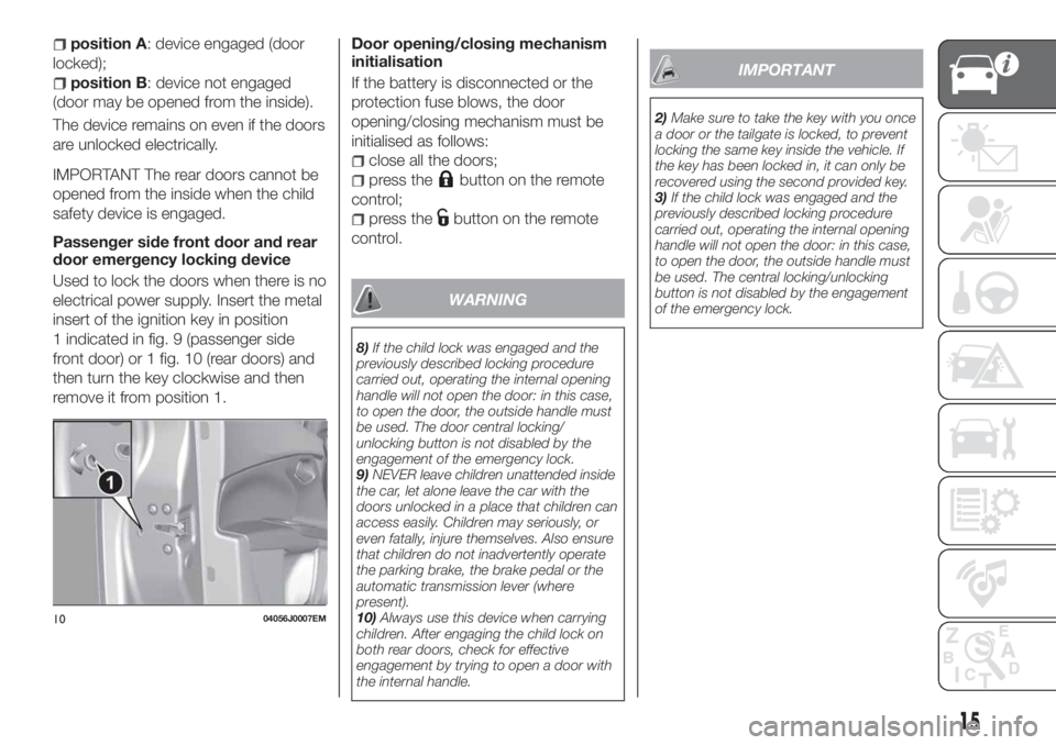
Used to lock the doors when there is no
electrical power supply. Insert the metal
insert of the ignition key in position
1 indicated in fig. 9 (passenger side
front door) or 1 fig. 10 (rear doors) and
then turn the key clockwise and then
remove it from position 1.Door opening/closing mechanism
initialisation
If the battery is disconnected or the
protection fuse blows, the door
opening/closing mechanism must be
initialised as follows:
close all the doors;
press thebutton on the remote
control;
press thebutton on the remote
control.
WARNING
8)If the child lock was engaged and the
previously described locking procedure
carried out, operating the internal opening
handle will not open the door: in this case,
to open the door, the outside handle must
be used. The door central locking/
unlocking button is not disabled by the
engagement of the emergency lock.
9)NEVER leave children unattended inside
the car, let alone leave the car with the
doors unlocked in a place that children can
access easily. Children may seriously, or
even fatally, injure themselves. Also ensure
that children do not inadvertently operate
the parking brake, the brake pedal or the
automatic transmission lever (where
present).
10)Always use this device when carrying
children. After engaging the child lock on
both rear doors, check for effective
engagement by trying to open a door with
the internal handle.
IMPORTANT
2)Make sure to take the key with you once
a door or the tailgate is locked, to prevent
locking the same key inside the vehicle. If
the key has been locked in, it can only be
recovered using the second provided key.
3)If the child lock was engaged and the
previously described locking procedure
carried out, operating the internal opening
handle will not open the door: in this case,
to open the door, the outside handle must
be used. The central locking/unlocking
button is not disabled by the engagement
of the emergency lock.
1004056J0007EM
15
Page 43 of 292
VERSION WITH LPG
SYSTEM
33) 34)
12) 13) 14) 15)
INTRODUCTION
The LPG version features two fuel
supply systems: one for petrol and one
for LPG.
PASSIVE SAFETY /
ACTIVE SAFETY
Passive safety
The car has the same passive safety
specifications as other versions. In
particular, the mountings of the tank
(located in the space-saver wheel
housing) have been designed to comply
with the Fiat safety standards for impact
tests.
When running on LPG, the flow of gas
(in a liquid state) leaving the tank
passes through the specific piping to
the pressure regulator unit, where there
is a safety solenoid valve that stops the
flow of LPG when the ignition key is
removed or when the driver selects a
fuel change (decision to run on petrol).
Together with the regulator solenoidvalve, a second solenoid valve, in the
tank, closes the LPG pipe at the tank
outlet.
The two solenoid valves are connected
to the fuel cut-off system (Fire
Protection System).
The LPG tank complies with the current
legal regulations of the countries where
the car is sold.
Active safety
The car has the same active safety
specifications as other versions.
Although the LPG system has
numerous safety features, it is advisable
to proceed as follows every time the car
is not in use for a long period or moved
in an emergency as a result of a
breakdown or accident:
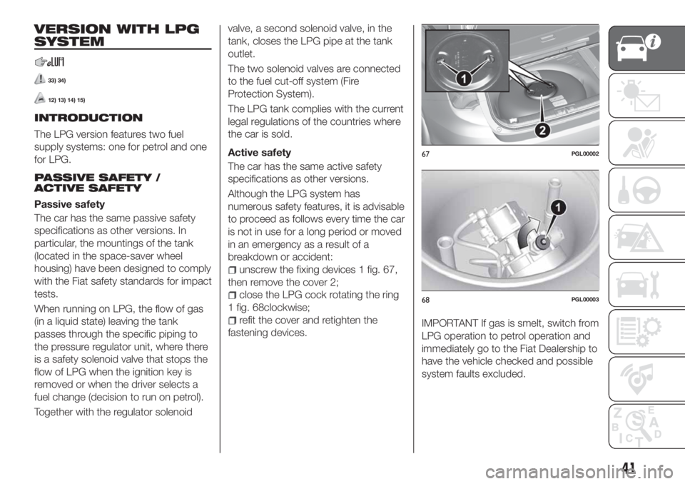
unscrew the fixing devices 1 fig. 67,
then remove the cover 2;
close the LPG cock rotating the ring
1 fig. 68clockwise;
refit the cover and retighten the
fastening devices.IMPORTANT If gas is smelt, switch from
LPG operation to petrol operation and
immediately go to the Fiat Dealership to
have the vehicle checked and possible
system faults excluded.
67PGL00002
68PGL00003
41
Page 46 of 292
14)When painting in an oven, the LPG tank
must be removed from the car and later
refitted by a Fiat Dealership. Although the
LPG system has numerous safety features,
it is advisable to proceed as follows every
time the vehicle is not in use for a long
period or moved in an emergency as a
result of a breakdown or accident: unscrew
the devices fastening the cover of the LPG
tank, then remove it. Close the LPG cock
rotating the ring nut clockwise (see
"Passive safety / active safety"). Refit the
cover and retighten the fastening devices.
15)When switching is requested, metallic
noise from the valves which pressurise the
circuit can be heard. For the switching logic
described above, a delay between the
valve ticking and the switching off of the
instrument panel indication is completely
normal.
16)Do not switch between the two
operating modes whilst starting the engine.17)In particular usage conditions, such as
starting and operation at low ambient
temperature or LPG supply with low
propane content, the system may switch
temporarily to petrol operation, without a
visual indication of switching on the
instrument panel. In the event of low LPG
levels in the tank or request for high
performance (e.g. overtaking, car fully
laden, steep hills) the system may
automatically switch to petrol operation to
guarantee the engine power requested; the
green warning light
on the instrument
panel switches on to indicate this. When
the above conditions are no longer present,
the system automatically restores LPG
operation; the green warning light
switches off. To achieve the automatic
switching described above, make sure that
there is always enough fuel in the petrol
tank.
18)It is strictly forbidden to use any
additive in the LPG. Periodically (at least
once every six months) it is advisable to let
the LPG in the tank run out and, at the first
refuelling, to check that it does not exceed
the maximum capacity of 42 litres (reserve
included) (with a tolerance of 1 litres
excess). If the level is above 42 litres
(reserve included) contact a Fiat Dealership
immediately.
19)Only use LPG for motor vehicles.
ACTIVE GRILLE
SHUTTER
(where provided)
Your vehicle may be equipped with
Active Grille Shutter, an automatic
system with mobile flaps applied in front
of the cooling module, whose
automatic opening/closing movement
aims at improving the vehicle
aerodynamic efficiency and thus
reducing consumption while ensuring
optimal engine operating temperature
conditions.
When a greater air flow is required for
cooling (e.g. when driving in urban
traffic), the flaps open, whereas when
temperature is low or the air flow is
enough (for example when driving in
motorways), the grille closes.
In case of failure, the instrument panel
will show the warning light
.
44
KNOWING YOUR CAR
Page 55 of 292
MAIN MENU
The Menu includes the following items:
“Dimmer” (lighting)
“Speed”
“Hour” (Set time)
“Buzzer” (Acoustic warning)
“Units” (Units of measure)
“Corner” (Cornering lights)
“Bag P” (Passenger air bag)
“DRL” (Daytime running lights) (for
versions/markets where provided)
Bag P (Passenger airbag)
This function is used to activate/
deactivate the front passenger's airbag.
Proceed as follows:
press theOKbutton and, after the
display shows the message (Passenger
Bag: Off, to deactivate) or the message
"Bag pass: On, to activate) by pressing
/, press thebutton;
a confirmation request message will
appear on the display;
press buttons/to select (Yes)
(confirming activation/deactivation) or
(No) (to abort);
press theOKbutton briefly: a
message confirming the selection is
displayed and you can return to the
menu screen.
WithPassenger's protection not
activethe
LED comes on
constantly in the instrument panel
dashboard.
NOTE With theUconnect™system,
some Menu items are shown and
managed on the display of the latter
and not on the instrument panel display
(refer to the dedicated Multimedia
chapter or to the supplement available
online).
RECONFIGURABLE
MULTIFUNCTION
DISPLAY
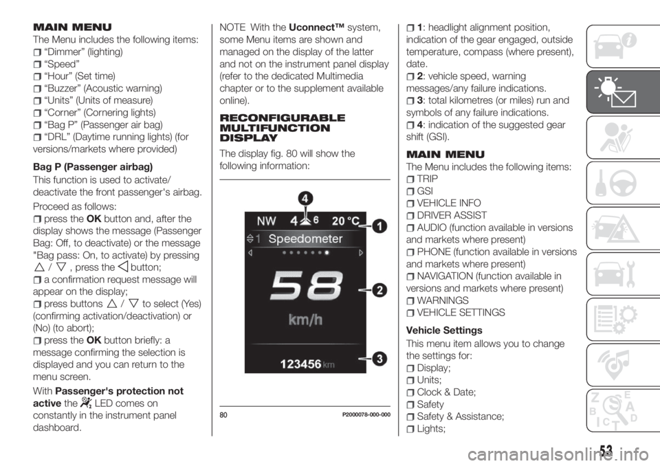
The display fig. 80 will show the
following information:
1: headlight alignment position,
indication of the gear engaged, outside
temperature, compass (where present),
date.
2: vehicle speed, warning
messages/any failure indications.
3: total kilometres (or miles) run and
symbols of any failure indications.
4: indication of the suggested gear
shift (GSI).
MAIN MENU
The Menu includes the following items:
TRIP
GSI
VEHICLE INFO
DRIVER ASSIST
AUDIO (function available in versions
and markets where present)
PHONE (function available in versions
and markets where present)
NAVIGATION (function available in
versions and markets where present)
WARNINGS
VEHICLE SETTINGS
Vehicle Settings
This menu item allows you to change
the settings for:
Display;
Units;
Clock & Date;
Safety
Safety & Assistance;
Lights;
80P2000078-000-000
53
Page 56 of 292
Doors & Locks.
Display
By selecting item "Display" you can
access the settings/information
regarding: " Display Settings”,
Language", "See phone" (available in
versions and markets where present),
"See navigation" (available in versions
and markets where present),
"Automatic reset Trip B", “Display
lighting”.
Units
Select item "Units" to choose the unit of
measurement between: "Imperial",
"Metric", "Customised".
Clock & Date
Select item "Clock & Date" to make the
following adjustments: "Set time", "Time
format", "Set date".
Safety
Select item "Security" to make the
following adjustments: "Passenger
AIRBAG", "Speed warning", "Seat belt
buzzer".
"Passenger AIRBAG" adjustment allows
you to activate/deactivate the
passenger airbag.Passenger's
protection not active: the
LED
comes on constantly in the dashboard
dashboard.Safety & Assistance
Select item "Safety & Assistance" to
make the following adjustments: Rain
sensor, Warning Volume, Brake Control,
Brake C.Sensivity, Park Assist, Vol. Park
Assist.
Lights
Select item "Lights" to make the
following adjustments: "Courtesy
lights", "Daytime running lights",
"Cornering lights", "Headlamp sensor",
"Follow me home".
Doors & Locks
Select item "Doors & Locks" to make
the following adjustments: "Autoclose",
"Flash Lights w/Lock", "Auto unlock on
exit".
NOTE With theUconnect™system,
some Menu items are shown and
managed on the display of the latter
and not on the instrument panel display
(refer to the dedicated Multimedia
chapter or to the supplement available
online).CONTROL BUTTONS
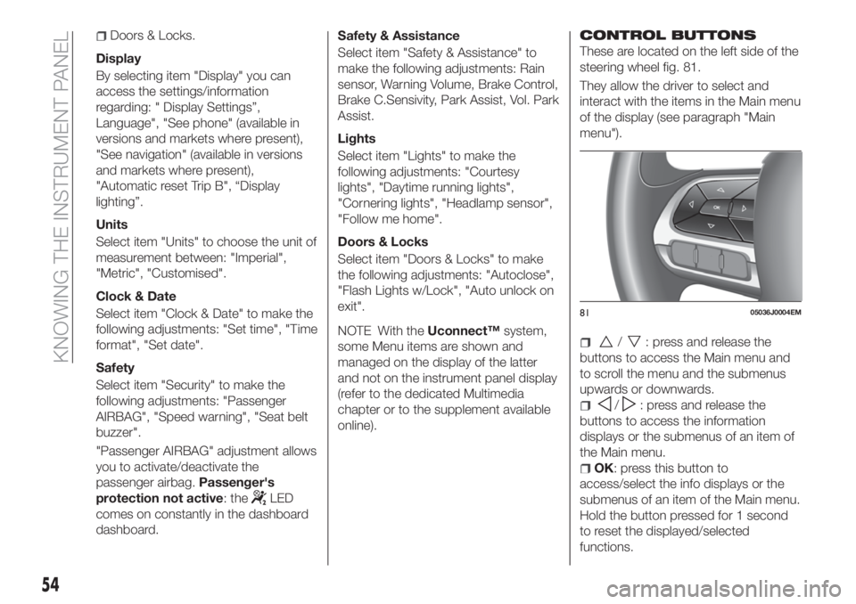
These are located on the left side of the
steering wheel fig. 81.
They allow the driver to select and
interact with the items in the Main menu
of the display (see paragraph "Main
menu").
/: press and release the
buttons to access the Main menu and
to scroll the menu and the submenus
upwards or downwards.
/: press and release the
buttons to access the information
displays or the submenus of an item of
the Main menu.
OK: press this button to
access/select the info displays or the
submenus of an item of the Main menu.
Hold the button pressed for 1 second
to reset the displayed/selected
functions.
8105036J0004EM
54
KNOWING THE INSTRUMENT PANEL
Page 142 of 292
BULBS TYPES
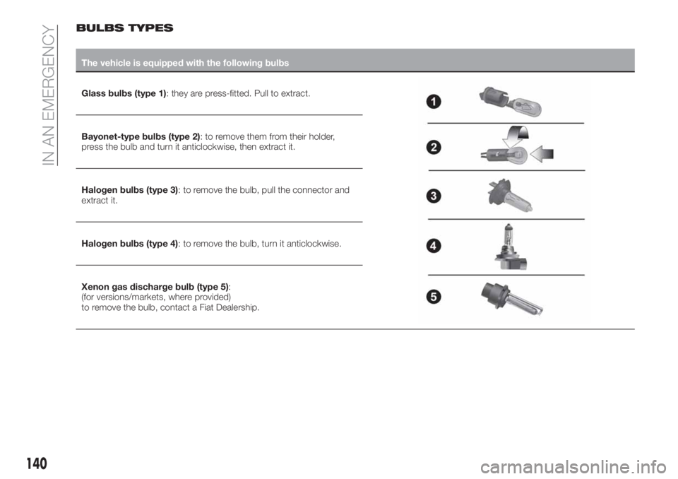
The vehicle is equipped with the following bulbs
Glass bulbs (type 1): they are press-fitted. Pull to extract.
Bayonet-type bulbs (type 2): to remove them from their holder,
press the bulb and turn it anticlockwise, then extract it.
Halogen bulbs (type 3): to remove the bulb, pull the connector and
extract it.
Halogen bulbs (type 4): to remove the bulb, turn it anticlockwise.
Xenon gas discharge bulb (type 5):
(for versions/markets, where provided)
to remove the bulb, contact a Fiat Dealership.
140
IN AN EMERGENCY
Page 144 of 292
REPLACING AN
EXTERNAL BULB
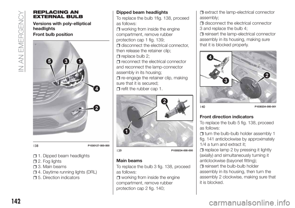
Versions with poly-elliptical
headlights
Front bulb position
1. Dipped beam headlights
2. Fog lights
3. Main beams
4. Daytime running lights (DRL)
5. Direction indicatorsDipped beam headlights
To replace the bulb 1fig. 138, proceed
as follows:
working from inside the engine
compartment, remove rubber
protection cap 1 fig. 139;
disconnect the electrical connector,
then release the retainer clip;
replace bulb 2;
reconnect the electrical connector
and reconnect the lamp-connector
assembly in its housing;
re-engage the retainer clip, making
sure that it is secured;
refit the rubber cap 1.
Main beams
To replace the bulb 3 fig. 138, proceed
as follows:
working from inside the engine
compartment, remove rubber
protection cap 2 fig. 140;
extract the lamp-electrical connector
assembly;
disconnect the electrical connector
3 and replace the bulb 4;
reinsert the lamp-electrical connector
assembly in its housing, making sure
that it is blocked properly.
Front direction indicators
To replace the bulb 5 fig. 138, proceed
as follows:
turn the bulb-bulb holder assembly 1
fig. 141 anticlockwise by approximately
1/4 a turn and extract it;
replace lamp 2 by pressing it lightly
(axially) and simultaneously turning it
anticlockwise (bayonet fitting);
reinsert the bulb-bulb holder
assembly in its housing, then turn the
assembly 2 clockwise, making sure that
it is blocked.
138P1030127-000-000
139P1030234-000-000
140P1030234-000-001
142
IN AN EMERGENCY
Page 145 of 292

Front fog lamps
To replace the bulb 2 fig. 138, proceed
as follows:
steer the car wheels inwards;
undo screw 1 fig. 142 using the
screwdriver provided and remove
inspection flap 2;
turn the bulb-bulb holder assembly
3 anticlockwise by a 1/4 turn and
extract it;
disconnect the electrical connector
and replace the complete assembly;
reconnect the electrical connector to
the new bulb-bulb holder assembly;
fit the assembly in its housing,
turning it clockwise and making sure
that it is blocked properly;
finally, refit the inspection flap 1.
Daytime running lights (DRL)
The daytime running light bulbs 4
fig. 138 are LED to increase their
lifetime; therefore, they should not
require replacing. Contact the Fiat
Dealership in the event of any kind of
problem.
Side turn light
To replace the bulb, proceed as follows:
press the lens 1 fig. 143 to compress
in the internal clip 2, then pull the
cluster outwards; take great care not
damage the paintwork;;
turn the bulb holder 2 anticlockwise,
then extract the press-fit bulb 3 and
replace it;
refit the bulb holder 2 in the lens
1 and turn it clockwise;
refit the cluster making sure that the
internal clip clicks into position.Versions with bi-parabolic
headlights
Front bulb position
1. Dipped headlights
2. Fog lights
3. Main beam headlights / Daytime
running lights (DRL)/ Positions
4. Direction indicator.
141P2000185
142P2000135
143P1030251-000-000
14408026J0002EM
143
Page 146 of 292
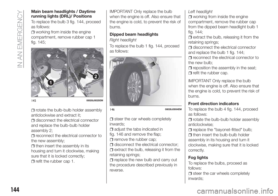
Main beam headlights / Daytime
running lights (DRL)/ Positions
To replace the bulb 3 fig. 144, proceed
as follows:
working from inside the engine
compartment, remove rubber cap 1
fig. 145;
rotate the bulb-bulb holder assembly
anticlockwise and extract it;
disconnect the electrical connector
and replace the bulb-bulb holder
assembly 2;
reconnect the electrical connector to
the new assembly;
then insert the assembly in its
housing and turn it clockwise, making
sure that it is locked correctly;
refit the rubber cap 1.
IMPORTANT Only replace the bulb
when the engine is off. Also ensure that
the engine is cold, to prevent the risk of
burns.
Dipped beam headlights
Right headlight
To replace the bulb 1 fig. 144, proceed
as follows:
steer the car wheels completely
inwards;
adjust the tabs indicated in
fig. 146 and remove the flap;
remove the rubber cap;
disconnect the electrical connector;
extract the bulb, releasing it from the
retaining springs;
replace the new bulb and carry out
the procedure described previously in
reverse.Left headlight
working from inside the engine
compartment, remove the rubber cap
from the dipped beam headlight bulb 1
fig. 144;
extract the bulb, releasing it from the
retaining springs;
disconnect the electrical connector
and replace the bulb 1 fig. 144;
reconnect the electrical connector to
the new bulb;
reposition the assembly in the seat;
refit the rubber cap.
IMPORTANT Only replace the bulb
when the engine is off. Also ensure that
the engine is cold, to prevent the risk of
burns.
Front direction indicators
To replace the bulb 4 fig. 144, proceed
as follows:
rotate the bulb-bulb holder assembly
anticlockwise;
replace the "bayonet-fitted" bulb;
then insert the bulb-bulb holder
assembly in its housing and turn it
clockwise, making sure that it is locked
correctly.
Fog lights
To replace the bulbs, proceed as
follows:
steer the car wheels completely
inwards;
14508026J0025EM
14608026J0004EM
144
IN AN EMERGENCY