fuse FIAT TIPO 5DOORS STATION WAGON 2018 Owner handbook (in English)
[x] Cancel search | Manufacturer: FIAT, Model Year: 2018, Model line: TIPO 5DOORS STATION WAGON, Model: FIAT TIPO 5DOORS STATION WAGON 2018Pages: 292, PDF Size: 7.74 MB
Page 10 of 292
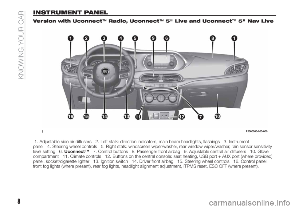
INSTRUMENT PANEL
Version with Uconnect™Radio, Uconnect™5" Live and Uconnect™5" Nav Live
1. Adjustable side air diffusers 2. Left stalk: direction indicators, main beam headlights, flashings 3. Instrument
panel 4. Steering wheel controls 5. Right stalk: windscreen wiper/washer, rear window wiper/washer, rain sensor sensitivity
level setting 6.Uconnect™7. Control buttons 8. Passenger front airbag 9. Adjustable central air diffusers 10. Glove
compartment 11. Climate controls 12. Buttons on the central console: seat heating, USB port + AUX port (where provided)
panel, socket/cigarette lighter 13. Ignition switch 14. Driver front airbag 15. Steering wheel controls 16. Control panel:
front fog lights (where present), rear fog lights, headlight alignment adjustment, iTPMS reset, ESC OFF (where present).
1P2000085-000-000
8
KNOWING YOUR CAR
Page 11 of 292
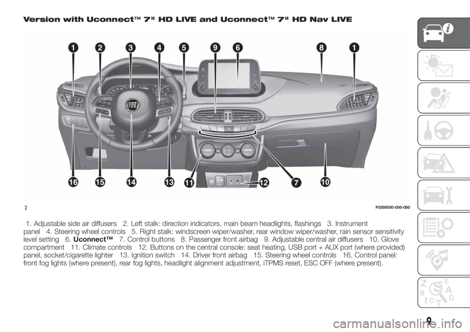
Version with Uconnect™7" HD LIVE and Uconnect™7" HD Nav LIVE
1. Adjustable side air diffusers 2. Left stalk: direction indicators, main beam headlights, flashings 3. Instrument
panel 4. Steering wheel controls 5. Right stalk: windscreen wiper/washer, rear window wiper/washer, rain sensor sensitivity
level setting 6.Uconnect™7. Control buttons 8. Passenger front airbag 9. Adjustable central air diffusers 10. Glove
compartment 11. Climate controls 12. Buttons on the central console: seat heating, USB port + AUX port (where provided)
panel, socket/cigarette lighter 13. Ignition switch 14. Driver front airbag 15. Steering wheel controls 16. Control panel:
front fog lights (where present), rear fog lights, headlight alignment adjustment, iTPMS reset, ESC OFF (where present).
2P2000050-000-000
9
Page 12 of 292
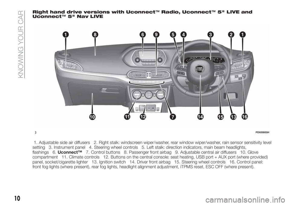
Right hand drive versions with Uconnect™Radio, Uconnect™5" LIVE and
Uconnect™5" Nav LIVE
1. Adjustable side air diffusers 2. Right stalk: windscreen wiper/washer, rear window wiper/washer, rain sensor sensitivity level
setting 3. Instrument panel 4. Steering wheel controls 5. Left stalk: direction indicators, main beam headlights,
flashings 6.Uconnect™7. Control buttons 8. Passenger front airbag 9. Adjustable central air diffusers 10. Glove
compartment 11. Climate controls 12. Buttons on the central console: seat heating, USB port + AUX port (where provided)
panel, socket/cigarette lighter 13. Ignition switch 14. Driver front airbag 15. Steering wheel controls 16. Control panel:
front fog lights (where present), rear fog lights, headlight alignment adjustment, iTPMS reset, ESC OFF (where present).
3PDX00003H
10
KNOWING YOUR CAR
Page 17 of 292
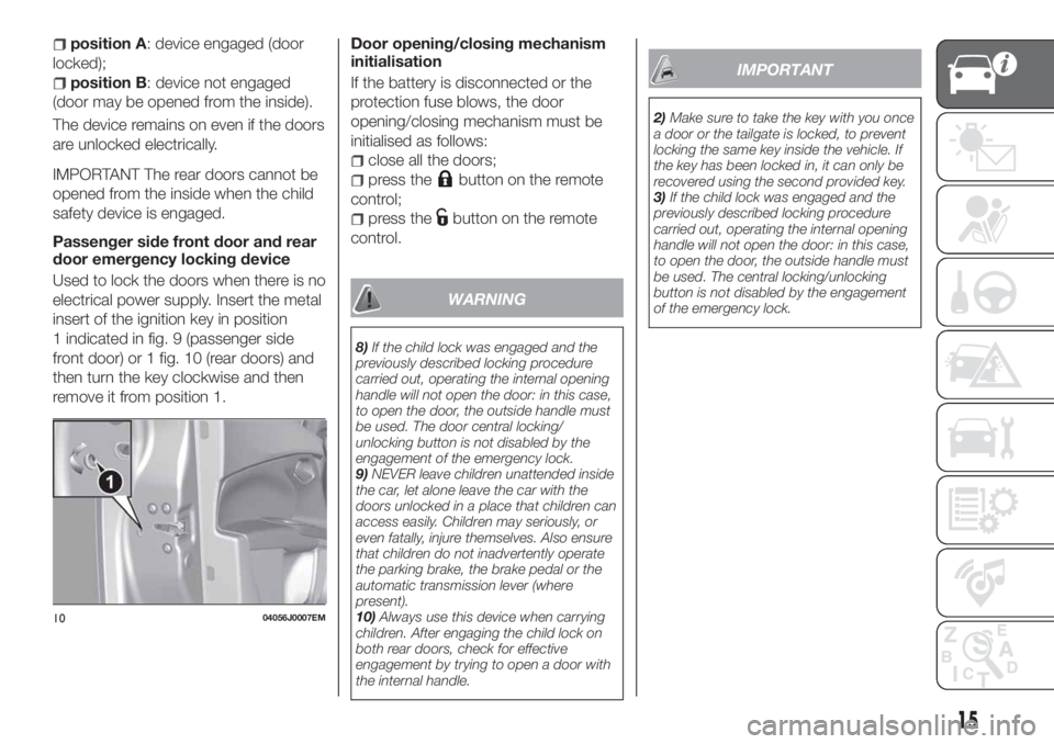
position A: device engaged (door
locked);
position B: device not engaged
(door may be opened from the inside).
The device remains on even if the doors
are unlocked electrically.
IMPORTANT The rear doors cannot be
opened from the inside when the child
safety device is engaged.
Passenger side front door and rear
door emergency locking device
Used to lock the doors when there is no
electrical power supply. Insert the metal
insert of the ignition key in position
1 indicated in fig. 9 (passenger side
front door) or 1 fig. 10 (rear doors) and
then turn the key clockwise and then
remove it from position 1.Door opening/closing mechanism
initialisation
If the battery is disconnected or the
protection fuse blows, the door
opening/closing mechanism must be
initialised as follows:
close all the doors;
press thebutton on the remote
control;
press thebutton on the remote
control.
WARNING
8)If the child lock was engaged and the
previously described locking procedure
carried out, operating the internal opening
handle will not open the door: in this case,
to open the door, the outside handle must
be used. The door central locking/
unlocking button is not disabled by the
engagement of the emergency lock.
9)NEVER leave children unattended inside
the car, let alone leave the car with the
doors unlocked in a place that children can
access easily. Children may seriously, or
even fatally, injure themselves. Also ensure
that children do not inadvertently operate
the parking brake, the brake pedal or the
automatic transmission lever (where
present).
10)Always use this device when carrying
children. After engaging the child lock on
both rear doors, check for effective
engagement by trying to open a door with
the internal handle.
IMPORTANT
2)Make sure to take the key with you once
a door or the tailgate is locked, to prevent
locking the same key inside the vehicle. If
the key has been locked in, it can only be
recovered using the second provided key.
3)If the child lock was engaged and the
previously described locking procedure
carried out, operating the internal opening
handle will not open the door: in this case,
to open the door, the outside handle must
be used. The central locking/unlocking
button is not disabled by the engagement
of the emergency lock.
1004056J0007EM
15
Page 37 of 292
When the CITY function is on, the
steering wheel effort is lighter, making
parking easier: therefore, this function is
particularly useful for driving in city
centres.
To ensure steering uniformity, when the
key is pressed while the steering wheel
is being turned, the change of force will
only be felt when it is turned in the
opposite direction, or the steering
wheel is released.
WARNING
28)It is absolutely forbidden to carry out
any after-market operation involving
steering system or steering column
modifications (e.g. installation of anti-theft
device) that could adversely affect
performance, invalidate the warranty, cause
serious safety problems and also result in
the car not meeting type-approval
requirements.
29)Before performing any maintenance
operations, always stop the engine and
remove the key from the ignition to lock the
steering column (especially when the car
wheels are not touching the ground). If this
is not possible (for example if the key
needs to be turned to MAR or the engine
must be running), remove the main fuse
that protects the electric power steering.
LUGGAGE
COMPARTMENT
IMPORTANT When travelling, do not
put any object on the rear parcel shelf
because they can injure passengers in
the event of an accident or sudden
braking.
OPENING
30)
Tailgate opening
When the central locking system is
unlocked, the tailgate can be opened
from outside the car using the electric
opening handle (where provided)
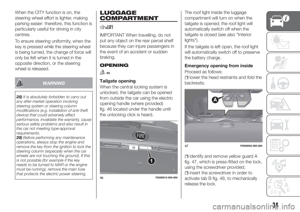
fig. 46 located under the handle until
the unlocking click is heard.The roof light inside the luggage
compartment will turn on when the
tailgate is opened; the roof light will
automatically switch off when the
tailgate is closed (see also "Interior
lights").
If the tailgate is left open, the roof light
will automatically switch off to preserve
the battery charge.
Emergency opening from inside
Proceed as follows:lower the head restraints and fold the
backrests;
identify and remove yellow guard A
fig. 47, which is press-fitted on the lock,
using the screwdriver provided;
insert the screwdriver in order to
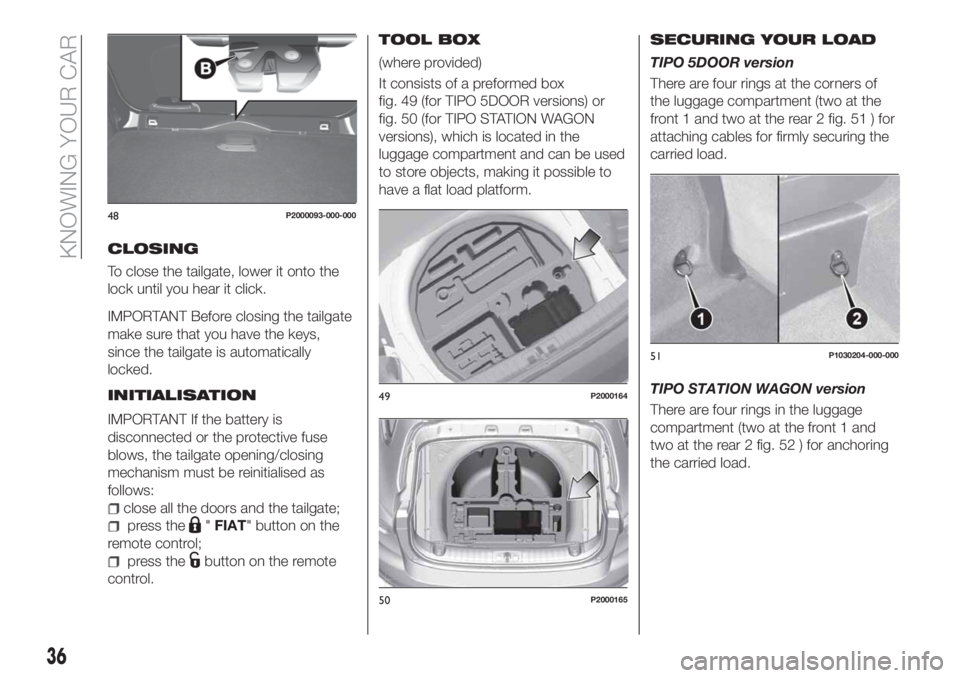
activate tab B fig. 48, to mechanically
release the lock.46P2000015-000-000
47P2000092-000-000
35
Page 38 of 292
CLOSING
To close the tailgate, lower it onto the
lock until you hear it click.
IMPORTANT Before closing the tailgate
make sure that you have the keys,
since the tailgate is automatically
locked.
INITIALISATION
IMPORTANT If the battery is
disconnected or the protective fuse
blows, the tailgate opening/closing
mechanism must be reinitialised as
follows:
close all the doors and the tailgate;
press the"FIAT" button on the
remote control;
press thebutton on the remote
control.
TOOL BOX
(where provided)
It consists of a preformed box
fig. 49 (for TIPO 5DOOR versions) or
fig. 50 (for TIPO STATION WAGON
versions), which is located in the
luggage compartment and can be used
to store objects, making it possible to
have a flat load platform.
SECURING YOUR LOAD
TIPO 5DOOR version
There are four rings at the corners of
the luggage compartment (two at the
front 1 and two at the rear 2 fig. 51 ) for
attaching cables for firmly securing the
carried load.
TIPO STATION WAGON version
There are four rings in the luggage
compartment (two at the front 1 and
two at the rear 2 fig. 52 ) for anchoring
the carried load.
48P2000093-000-000
49P2000164
50P2000165
51P1030204-000-000
36
KNOWING YOUR CAR
Page 71 of 292
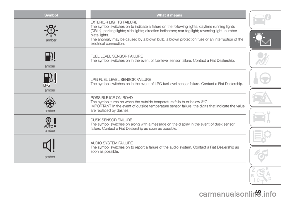
Symbol What it means
amberEXTERIOR LIGHTS FAILURE
The symbol switches on to indicate a failure on the following lights: daytime running lights
(DRLs); parking lights; side lights; direction indicators; rear fog light; reversing light; number
plate lights.
The anomaly may be caused by a blown bulb, a blown protection fuse or an interruption of the
electrical connection.
amberFUEL LEVEL SENSOR FAILURE
The symbol switches on in the event of fuel level sensor failure. Contact a Fiat Dealership.
amberLPG FUEL LEVEL SENSOR FAILURE
The symbol switches on in the event of LPG fuel level sensor failure. Contact a Fiat Dealership.
amberPOSSIBLE ICE ON ROAD
The symbol turns on when the outside temperature falls to or below 3°C.
IMPORTANT In the event of outside temperature sensor failure, the digits that indicate the value
are replaced by dashes.
amberDUSK SENSOR FAILURE
The symbol switches on along with a message on the display in the event of dusk sensor
failure. Contact a Fiat Dealership as soon as possible.
amberAUDIO SYSTEM FAILURE
The symbol switches on to report a failure of the audio system. Contact a Fiat Dealership as
soon as possible.
69
Page 140 of 292

IN AN EMERGENCY
A punctured tyre or a burnt-out bulb?
At times, a problem may interfere with
our journey.
The pages on emergencies can help
you to deal with critical situations
independently and with calm.
In an emergency we recommend that
you call the freephone number found in
the Warranty Booklet.
It is also possible to call the national or
international universal freephone
number to search for the nearest Fiat
Dealership.HAZARD WARNING LIGHTS.....139
BULB REPLACEMENT.........139
REPLACING FUSES..........148
CHANGING A WHEEL.........155
FIX&GO AUTOMATIC KIT.......159
JUMP STARTING............162
FUEL CUT-OFF SYSTEM.......164
AUTOMATIC TRANSMISSION. . . .166
DUAL-CLUTCH AUTOMATIC
TRANSMISSION............168
TOWING THE VEHICLE........169
138
IN AN EMERGENCY
Page 141 of 292
HAZARD WARNING
LIGHTS
CONTROL
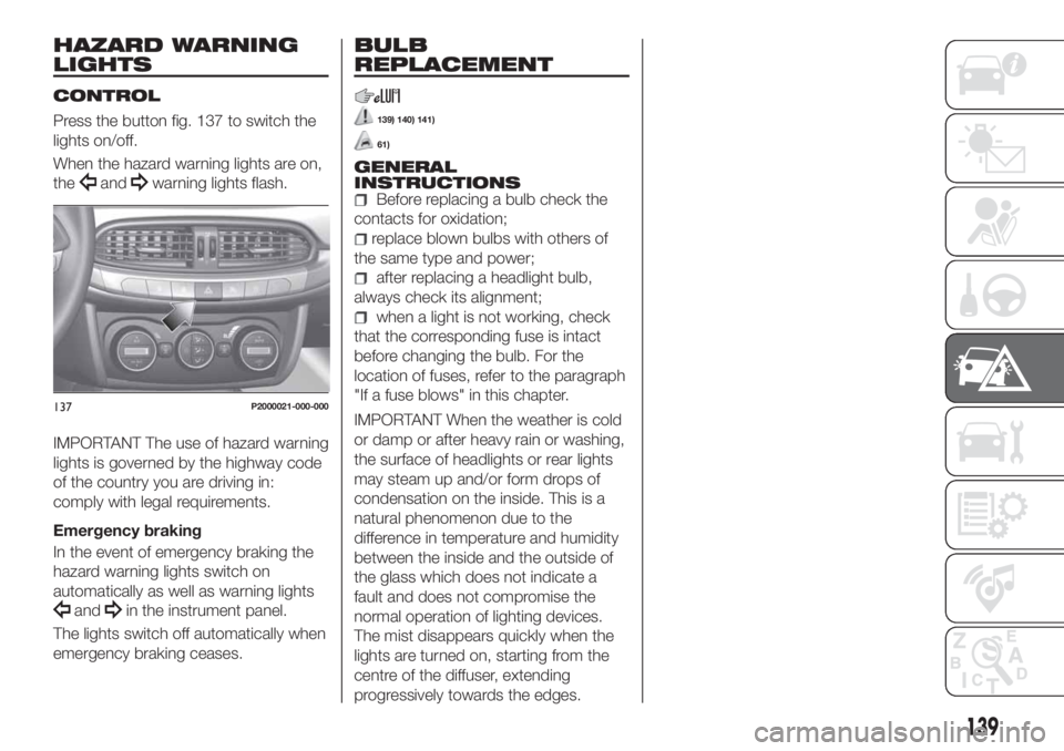
Press the button fig. 137 to switch the
lights on/off.
When the hazard warning lights are on,
the
andwarning lights flash.
IMPORTANT The use of hazard warning
lights is governed by the highway code
of the country you are driving in:
comply with legal requirements.
Emergency braking
In the event of emergency braking the
hazard warning lights switch on
automatically as well as warning lights
andin the instrument panel.
The lights switch off automatically when
emergency braking ceases.
BULB
REPLACEMENT
139) 140) 141)
61)
GENERAL
INSTRUCTIONS
Before replacing a bulb check the
contacts for oxidation;
replace blown bulbs with others of
the same type and power;
after replacing a headlight bulb,
always check its alignment;
when a light is not working, check
that the corresponding fuse is intact
before changing the bulb. For the
location of fuses, refer to the paragraph
"If a fuse blows" in this chapter.
IMPORTANT When the weather is cold
or damp or after heavy rain or washing,
the surface of headlights or rear lights
may steam up and/or form drops of
condensation on the inside. This is a
natural phenomenon due to the
difference in temperature and humidity
between the inside and the outside of
the glass which does not indicate a
fault and does not compromise the
normal operation of lighting devices.
The mist disappears quickly when the
lights are turned on, starting from the
centre of the diffuser, extending
progressively towards the edges.137P2000021-000-000
139
Page 150 of 292
WARNING
139)Modifications or repairs to the electric
system that are not carried out properly or
do not take the system technical
specifications into account can cause
malfunctions leading to the risk of fire.140)Halogen bulbs contain pressurised
gas, in the case of breakage they may
burst causing glass fragments to be
projected outwards.
141)Only replace the light bulbs when the
engine is off and in a position that does not
interfere with traffic and lets you safely
replace them (see the description in the
“Replacement” paragraph). Also ensure
that the engine is cold, to prevent the risk
of burns.
142)Before replacing the bulb, wait for the
exhaust ducts to cool down: DANGER OF
SCALDING!
IMPORTANT
61)Halogen bulbs must be handled
holding the metallic part only. Touching the
transparent part of the bulb with your
fingers may reduce the intensity of the
emitted light and even reduce the lifespan
of the bulb. In the event of accidental
contact, wipe the bulb with a cloth
moistened with alcohol and let the bulb dry.
REPLACING FUSES
GENERAL INFORMATION
143) 144) 145) 146)
62)
Fuses protect the electrical system:
they intervene (blow) in the event of a
failure or improper action on the
system.
Fuse extracting pliers
To replace a fuse, use the pliers hooked
inside the engine compartment fuse
box cover (see fig. 160 ).
The pliers have two different ends,
specifically designed to remove the
different types of fuses present in the
vehicle.
158P1030157-000-000
15908026J0026EM
148
IN AN EMERGENCY