battery FIAT TIPO 5DOORS STATION WAGON 2020 Owner handbook (in English)
[x] Cancel search | Manufacturer: FIAT, Model Year: 2020, Model line: TIPO 5DOORS STATION WAGON, Model: FIAT TIPO 5DOORS STATION WAGON 2020Pages: 304, PDF Size: 9.12 MB
Page 119 of 304
Activation
With gear lever in position D (Drive), to
activate the sequential drive mode,
move the lever to the left (– and +
indication of the panel). The gear
engaged will be shown on the display.
Gearshifting is made by moving the
gear lever forwards, towards symbol –
or backwards, towards symbol +.
Deactivation
To deactivate the sequential driving
mode, bring the gear lever back to
position D (Drive), automatic mode.
STARTING THE ENGINE
Engine start-up is allowed only with the
gear lever in P or N position.
Therefore, on starting the engine, the
system will be in the N or P position
(the latter corresponds to neutral, but
with the car wheels mechanically
locked).
MOVING THE CAR
To move the car, from P press the brake
pedal and, using the button on the gear
lever, move the lever to the desired
position (D, R or "Sequential mode").
The display will show the gear engaged.
When the brake pedal is released, the
car starts moving forwards or
backwards, as soon as the manoeuvre
is activated ("creeping" effect).The accelerator should not be pressed
in this case.
IMPORTANT The inconsistency
between the speed actually engaged
(shown on the display) and the position
of the gear lever is indicated by the
letter corresponding to the position of
the gear lever flashing on the panel
(also accompanied by an acoustic
warning). This condition should not be
interpreted as an operational fault, but
simply as a request by the system to
repeat the manoeuvre.
GEAR ENGAGEMENT
INHIBITION
This system prevents you from moving
the gear lever from position P (Park) or
N (Neutral) if the brake pedal has not
been previously depressed. When the
ignition device is in MAR (engine on or
off):
to move the shift lever to a position
other than P (Park) or from N to R, you
must press the brake pedal and the
button 1on the shift lever knob;
to shift the lever from position N to
position D, press the brake pedal.
In the event of a fault or when the
vehicle battery is flat, the lever remains
locked in the P position. To manually
release the lever, see the "Dual clutch
automatic transmission - Releasing the
lever" paragraph in the "In an
emergency" chapter.
STOPPING THE ENGINE
Versions equipped with key without
remote control: this function requires
the gear lever to be positioned at P
(Park) before extracting the key from the
ignition device. If the car battery is flat
and the ignition key is engaged, the
latter is locked in position. To remove
the key manually see the "Dual-clutch
automatic transmission - Key removal"
paragraph in the "In an emergency"
chapter.
Versions with a Stop/Start system:
in order to switch off the engine, the
vehicle needs to be stopped by
applying appropriate pressure on the
brake pedal. If the pressure is not
sufficient, the engine will not switch off.
This feature can be exploited so that
the engine does not switch off in
particular traffic conditions.
"RECOVERY"
FUNCTIONS
In case of a gear lever failure, the
instrument panel display could show a
dedicated message recommending that
the driver continues driving without
shifting the lever to the P position.
117
Page 121 of 304
NOTE The engine can only be stopped
automatically after exceeding a speed
of about 10 km/h. The
warning light
on the instrument panel switches on to
signal that the engine was stopped.
Restarting the engine
Versions with manual transmission
To restart the engine, press the clutch
pedal or the accelerator pedal.
If the car does not start when the clutch
is pressed, place the gear lever in
neutral and repeat the procedure. If the
problem persists, contact a Fiat
Dealership.
Versions with automatic
transmission
To restart the engine, release the brake
pedal.
With brake pressed, if the gear lever is
in automatic mode - D (Drive) - the
engine can be restarted by moving the
lever to R (Reverse) or "AutoStick".
With brake pressed, if the gear lever is
in "AutoStick" mode, the engine can be
restarted by moving the lever to R
(Reverse).When the engine has been stopped
automatically, keeping the brake pedal
pressed, the brake can be released
keeping the engine off by quickly
shifting the gear lever to P (Park).
To restart the engine, just move the
lever out of position P.
SYSTEM MANUAL
ACTIVATION/
DEACTIVATION
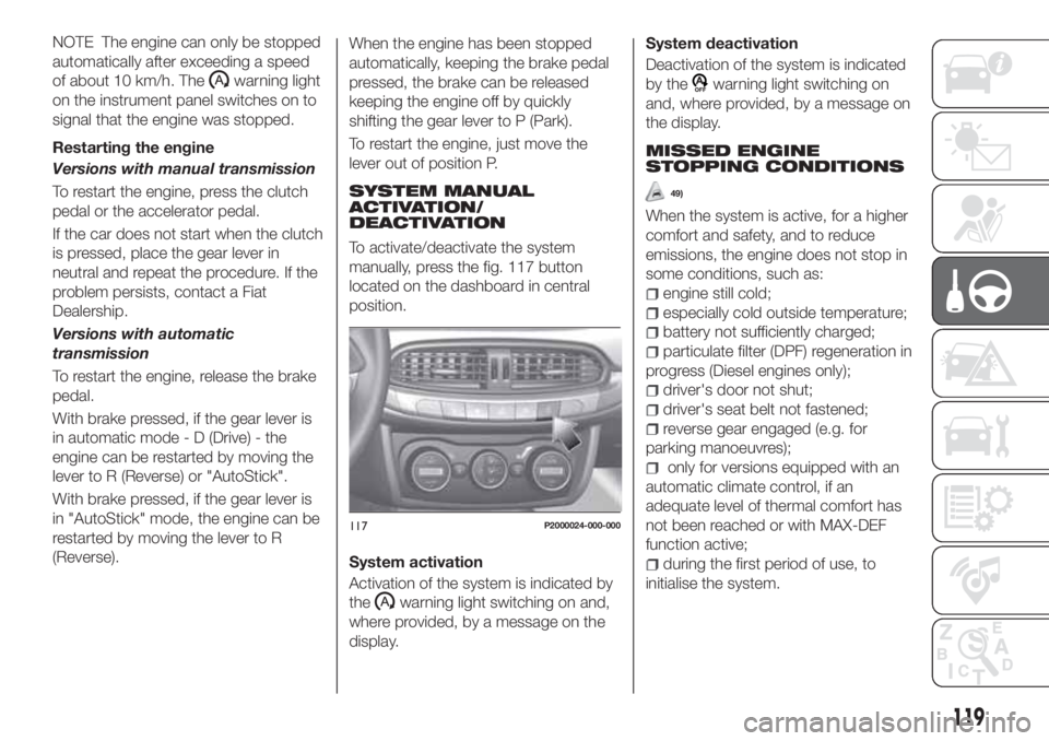
To activate/deactivate the system
manually, press the fig. 117 button
located on the dashboard in central
position.
System activation
Activation of the system is indicated by
the
warning light switching on and,
where provided, by a message on the
display.System deactivation
Deactivation of the system is indicated
by the
warning light switching on
and, where provided, by a message on
the display.
MISSED ENGINE
STOPPING CONDITIONS
49)
When the system is active, for a higher
comfort and safety, and to reduce
emissions, the engine does not stop in
some conditions, such as:
engine still cold;
especially cold outside temperature;
battery not sufficiently charged;
particulate filter (DPF) regeneration in
progress (Diesel engines only);
driver's door not shut;
driver's seat belt not fastened;
reverse gear engaged (e.g. for
parking manoeuvres);
only for versions equipped with an
automatic climate control, if an
adequate level of thermal comfort has
not been reached or with MAX-DEF
function active;
during the first period of use, to
initialise the system.
117P2000024-000-000
119
Page 122 of 304
ENGINE RESTARTING
CONDITIONS
Due to comfort, emission control and
safety reasons, the engine can restart
automatically without any action by the
driver, when the car and the passenger
compartment climate control system
are in certain conditions, such as:
With gear engaged, automatic engine
restarting is possible only by fully
pressing the clutch pedal.
SAFETY FUNCTIONS
When the engine is stopped through
the Stop/Start system, if the driver
releases their seat belt or opens the
driver's or passenger's door, the engine
can be restarted only by using the
ignition device.
This condition is indicated to the driver
both through a buzzer and a message
on the display.
"ENERGY SAVING"
FUNCTION
If, following the automatic engine
restarting, the driver does not carry out
any action for more than 3 minutes, the
Stop/Start system stops the engine
definitely, to prevent fuel consumption.
In these cases, the engine can only be
restarted using the ignition device.NOTE In any case, it is possible to keep
the engine running by deactivating the
system.
IRREGULAR OPERATION
In the event of malfunction, the
Stop/Start system is deactivated.
For failure indications, see the "Warning
lights and messages" paragraph,
"Knowing the instrument panel"
chapter.
VEHICLE INACTIVITY
122)
In the event of vehicle inactivity (or if the
battery is replaced), special attention
must be paid to the disconnection of
the battery power supply.
WARNING
122)If the battery needs to be replaced,
always contact a Fiat Dealership. Replace
the battery with a new one of the same
type and specifications.
IMPORTANT
49)If the climate comfort is to be favoured,
the Start&Stop system can be deactivated,
for a continuous operation of the climate
control system.
SPEED LIMITER
(where provided)
DESCRIPTION
This device allows the speed of the
vehicle to be limited to values which
can be set by the driver.
The maximum speed can be set both
with vehicle stationary and in motion.
The minimum speed that can be set is
30 km/h.
When the device is active, the vehicle
speed depends on the pressure at the
accelerator pedal, until the
programmed speed limit is reached
(see "Speed limit programming"
paragraph).
120
STARTING AND DRIVING
Page 139 of 304
Do not exceed the speed limits specific
to each country you are driving in, in the
case of vehicles towing trailers. In any
case, the top speed must not exceed
100 km/h.
Any electric brake must be powered
directly by the battery through a cable
with a cross-section of no less than
2.5 mm
2.
In addition to the electrical branches,
the vehicle electrical system can only be
connected to the supply cable for an
electric brake and to the cable for an
internal light for the trailer, not
exceeding 15 W. For connections, use
the preset control unit with a battery
cable with section not less than 2.5 mm
2.
IMPORTANT The use of auxiliary loads
other than external lights (e.g. electric
brake) must take place with engine
running.
INSTALLING A TOW
HOOK
To install a tow hook contact a Fiat
Dealership.
WARNING
134)The ABS with which the car is
equipped will not control the braking
system of the trailer. Particular caution is
required on slippery roads.
135)Never modify the braking system of
the vehicle to control the trailer brake. The
trailer braking system must be fully
independent of the car’s hydraulic system.
SUGGESTIONS FOR
DRIVING
SAVING FUEL
Below are some suggestions which
may help you save fuel and thus lower
the amount of harmful emissions
released into the atmosphere.
Vehicle maintenance
Checks and operations should be
carried out in accordance with the
"Scheduled Servicing Plan" (see the
"Maintenance and care" chapter).
Tyres
Check the tyre pressures at least once
every four weeks: if the pressure is too
low, consumption levels increase as
resistance to rolling is higher.
Unnecessary loads
Do not travel with an overloaded boot.
The weight of the vehicle and its
arrangement greatly affect fuel
consumption and stability.
Roof rack/ski rack
(where provided)
Remove the roof rack or the ski rack
from the roof when they are not used.
These accessories lower aerodynamic
penetration and adversely affect
137
consumption levels.
Page 158 of 304
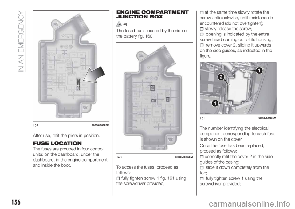
After use, refit the pliers in position.
FUSE LOCATION
The fuses are grouped in four control
units: on the dashboard, under the
dashboard, in the engine compartment
and inside the boot.
ENGINE COMPARTMENT
JUNCTION BOX
64)
The fuse box is located by the side of
the battery fig. 160.
To access the fuses, proceed as
follows:
fully tighten screw 1 fig. 161 using
the screwdriver provided;
at the same time slowly rotate the
screw anticlockwise, until resistance is
encountered (do not overtighten);
slowly release the screw;
opening is indicated by the entire
screw head coming out of its housing;
remove cover 2, sliding it upwards
on the side guides, as indicated in the
figure.
The number identifying the electrical
component corresponding to each fuse
is shown on the cover.
Once the fuse has been replaced,
proceed as follows:
correctly refit the cover 2 in the side
guides of the casing;
slide it down completely from the
top;
fully tighten screw 1 using the
screwdriver provided;
15908036J0002EM
16008036J0005EM
16108036J0006EM
156
IN AN EMERGENCY
Page 171 of 304
IMPORTANT
67)The sealant is effective with external
temperatures of between -40°C and
+55°C. The sealant has an expiry date. It is
possible to repair tyres which have been
damaged on tread up to a diameter of
6 mm. Show the cartridge and the label to
the personnel charged with handling the
tyre treated with the tyre repair kit.
JUMP STARTING
157) 158) 159) 160)
68)
If the battery is flat, a jump starting can
be performed using the battery and the
cables of another vehicle, or using an
auxiliary battery. In all cases, the battery
used must have a capacity equal to or
a little higher than the flat one.
Jump starting may be dangerous if
carried out incorrectly: carefully follow
the procedures described below.
JUMP STARTING
IMPORTANT NOTES
Do not use an auxiliary battery or any
other source of external supply with a
voltage above 12 V: the battery, the
starter, the alternator and the electrical
system of the vehicle could be
damaged.
Do not attempt jump starting if the
battery is frozen. The battery could
break and explode!
When jump starting, never connect the
negative lead (–) of the auxiliary battery
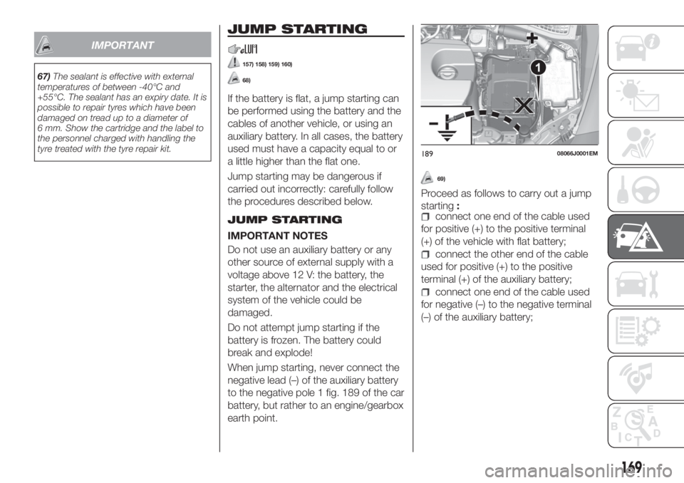
to the negative pole 1 fig. 189 of the car
battery, but rather to an engine/gearbox
earth point.
69)
Proceed as follows to carry out a jump
starting:
connect one end of the cable used
for positive (+) to the positive terminal
(+) of the vehicle with flat battery;
connect the other end of the cable
used for positive (+) to the positive
terminal (+) of the auxiliary battery;
connect one end of the cable used
for negative (–) to the negative terminal
(–) of the auxiliary battery;
18908066J0001EM
169
Page 172 of 304
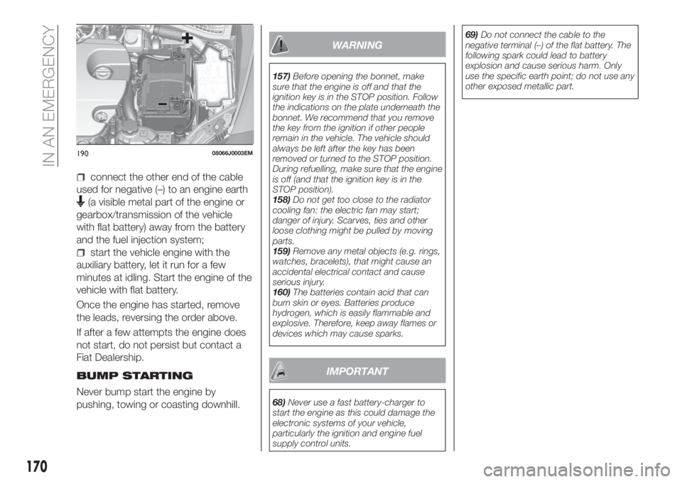
connect the other end of the cable
used for negative (–) to an engine earth
(a visible metal part of the engine or
gearbox/transmission of the vehicle
with flat battery) away from the battery
and the fuel injection system;
start the vehicle engine with the
auxiliary battery, let it run for a few
minutes at idling. Start the engine of the
vehicle with flat battery.
Once the engine has started, remove
the leads, reversing the order above.
If after a few attempts the engine does
not start, do not persist but contact a
Fiat Dealership.
BUMP STARTING
Never bump start the engine by
pushing, towing or coasting downhill.
WARNING
157)Before opening the bonnet, make
sure that the engine is off and that the
ignition key is in the STOP position. Follow
the indications on the plate underneath the
bonnet. We recommend that you remove
the key from the ignition if other people
remain in the vehicle. The vehicle should
always be left after the key has been
removed or turned to the STOP position.
During refuelling, make sure that the engine
is off (and that the ignition key is in the
STOP position).
158)Do not get too close to the radiator
cooling fan: the electric fan may start;
danger of injury. Scarves, ties and other
loose clothing might be pulled by moving
parts.
159)Remove any metal objects (e.g. rings,
watches, bracelets), that might cause an
accidental electrical contact and cause
serious injury.
160)The batteries contain acid that can
burn skin or eyes. Batteries produce
hydrogen, which is easily flammable and
explosive. Therefore, keep away flames or
devices which may cause sparks.
IMPORTANT
68)Never use a fast battery-charger to
start the engine as this could damage the
electronic systems of your vehicle,
particularly the ignition and engine fuel
supply control units.69)Do not connect the cable to the
negative terminal (–) of the flat battery. The
following spark could lead to battery
explosion and cause serious harm. Only
use the specific earth point; do not use any
other exposed metallic part.
19008066J0003EM
170
IN AN EMERGENCY
Page 173 of 304
FUEL CUT-OFF
SYSTEM
DESCRIPTION
Diesel and petrol versions
This intervenes in the case of an impact
causing:
the interruption of the fuel supply
with the engine consequently switching
off;
the automatic unlocking of the
doors;
turning on of the lights inside the
vehicle;
deactivation of climate control
system ventilation;
switching on of the hazard warning
lights (to deactivate the lights press the
button on the dashboard).
On some versions, the intervention of
the system is indicated by a message
shown on the display. In the same way,
a dedicated message on the display
warns the driver if system operation is
compromised.
IMPORTANT Carefully check the vehicle
for fuel leaks, for instance in the engine
compartment, under the vehicle or near
the tank area. After a collision, bring the
ignition device to STOP to prevent the
battery from running down.
LPG versions
(where provided)
On LPG versions, in addition to the
above, the fuel cut-off system stops
petrol supply immediately, closes the
LPG safety solenoid valve and stops
injection, consequently shutting off the
engine.
171
Page 175 of 304
AUTOMATIC
TRANSMISSION
Lever release
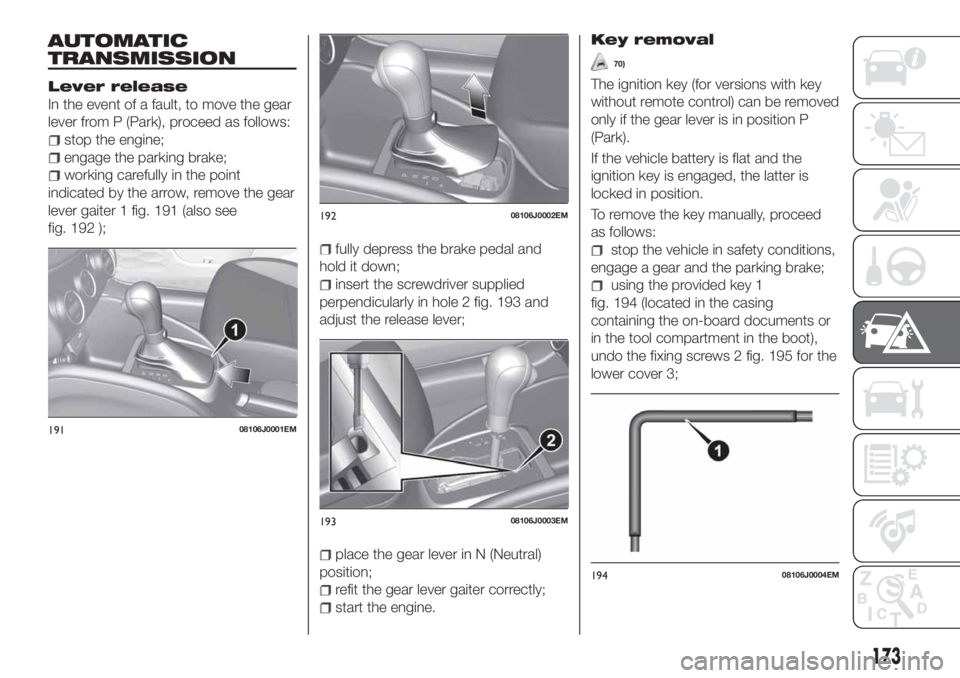
In the event of a fault, to move the gear
lever from P (Park), proceed as follows:
stop the engine;
engage the parking brake;
working carefully in the point
indicated by the arrow, remove the gear
lever gaiter 1 fig. 191 (also see
fig. 192 );
fully depress the brake pedal and
hold it down;
insert the screwdriver supplied
perpendicularly in hole 2 fig. 193 and
adjust the release lever;
place the gear lever in N (Neutral)
position;
refit the gear lever gaiter correctly;
start the engine.
Key removal
70)
The ignition key (for versions with key
without remote control) can be removed
only if the gear lever is in position P
(Park).
If the vehicle battery is flat and the
ignition key is engaged, the latter is
locked in position.
To remove the key manually, proceed
as follows:
stop the vehicle in safety conditions,
engage a gear and the parking brake;
using the provided key 1
fig. 194 (located in the casing
containing the on-board documents or
in the tool compartment in the boot),
undo the fixing screws 2 fig. 195 for the
lower cover 3;
19108106J0001EM
19208106J0002EM
19308106J0003EM
19408106J0004EM
173
Page 177 of 304
DUAL-CLUTCH
AUTOMATIC
TRANSMISSION
Lever release
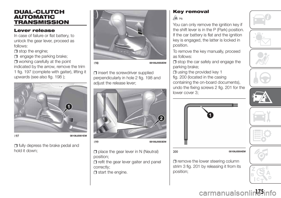
In case of failure or flat battery, to
unlock the gear lever, proceed as
follows:
stop the engine;
engage the parking brake;
working carefully at the point
indicated by the arrow, remove the trim
1 fig. 197 (complete with gaiter), lifting it
upwards (see also fig. 198 );
fully depress the brake pedal and
hold it down;
insert the screwdriver supplied
perpendicularly in hole 2 fig. 198 and
adjust the release lever;
place the gear lever in N (Neutral)
position;
refit the gear lever gaiter and panel
correctly;
start the engine.
Key removal
71)
You can only remove the ignition key if
the shift lever is in the P (Park) position.
If the car battery is flat and the ignition
key is engaged, the latter is locked in
position.
To remove the key manually, proceed
as follows:
stop the car safely and engage the
parking brake;
using the provided key 1
fig. 200 (located in the casing
containing the on-board documents),
undo the fixing screws 2 fig. 201 for the
lower cover 3;
remove the lower steering column
strim 3 fig. 201 by releasing it from its
position;
19708106J0001EM
19808106J0002EM
19908106J0003EM
20008106J0004EM
175