steering FIAT TIPO 5DOORS STATION WAGON 2020 Owner handbook (in English)
[x] Cancel search | Manufacturer: FIAT, Model Year: 2020, Model line: TIPO 5DOORS STATION WAGON, Model: FIAT TIPO 5DOORS STATION WAGON 2020Pages: 304, PDF Size: 9.12 MB
Page 131 of 304
When the conditions limiting the system
functions end, this will go back to
normal and complete operation. Should
the fault persist, contact a Fiat
Dealership.
PRECAUTIONS WHILE
DRIVING
The device may not work correctly in
some driving conditions (see below):
the driver must control the vehicle at all
times.
Towing a trailer
Use of the device is not recommended
while towing a trailer.
Vehicle not aligned
The device may not detect a vehicle
travelling on the same lane but which is
not aligned along the same direction of
travel or a vehicle which is cutting in
from a side lane. Sufficient distance
from the vehicles ahead may not be
guaranteed in these cases.
The non-aligned vehicle can weave in
and out of the driving direction causing
the vehicle to brake or accelerate
unexpectedly.
Steering and curves
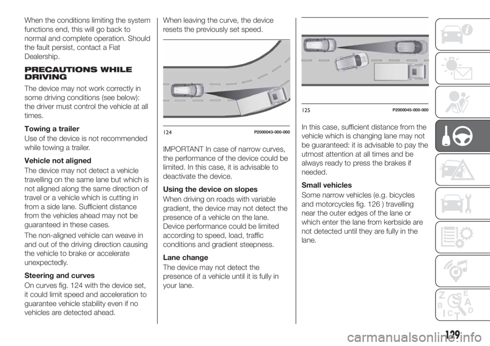
On curves fig. 124 with the device set,
it could limit speed and acceleration to
guarantee vehicle stability even if no
vehicles are detected ahead.When leaving the curve, the device
resets the previously set speed.
IMPORTANT In case of narrow curves,
the performance of the device could be
limited. In this case, it is advisable to
deactivate the device.
Using the device on slopes
When driving on roads with variable
gradient, the device may not detect the
presence of a vehicle on the lane.
Device performance could be limited
according to speed, load, traffic
conditions and gradient steepness.
Lane change
The device may not detect the
presence of a vehicle until it is fully in
your lane.In this case, sufficient distance from the
vehicle which is changing lane may not
be guaranteed: it is advisable to pay the
utmost attention at all times and be
always ready to press the brakes if
needed.
Small vehicles
Some narrow vehicles (e.g. bicycles
and motorcycles fig. 126 ) travelling
near the outer edges of the lane or
which enter the lane from kerbside are
not detected until they are fully in the
lane.
124P2000043-000-000
125P2000045-000-000
129
Page 137 of 304
SYMBOLS AND MESSAGES ON THE DISPLAY
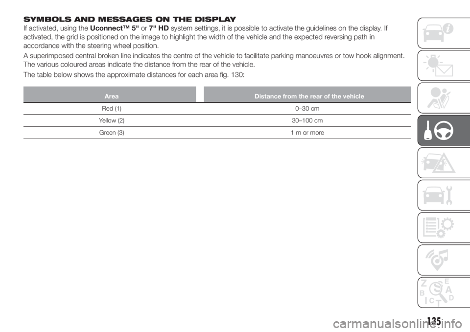
If activated, using theUconnect™ 5"or7" HDsystem settings, it is possible to activate the guidelines on the display. If
activated, the grid is positioned on the image to highlight the width of the vehicle and the expected reversing path in
accordance with the steering wheel position.
A superimposed central broken line indicates the centre of the vehicle to facilitate parking manoeuvres or tow hook alignment.
The various coloured areas indicate the distance from the rear of the vehicle.
The table below shows the approximate distances for each area fig. 130:
Area Distance from the rear of the vehicle
Red (1) 0–30 cm
Yellow (2) 30–100 cm
Green (3) 1 m or more
135
Page 159 of 304
at the same time slowly rotate the
screw clockwise, until resistance is
encountered (do not overtighten);
slowly release the screw;
closure is indicated by the securing
of the entire screw head in its housing.
DASHBOARD FUSE BOX
Left-hand drive version
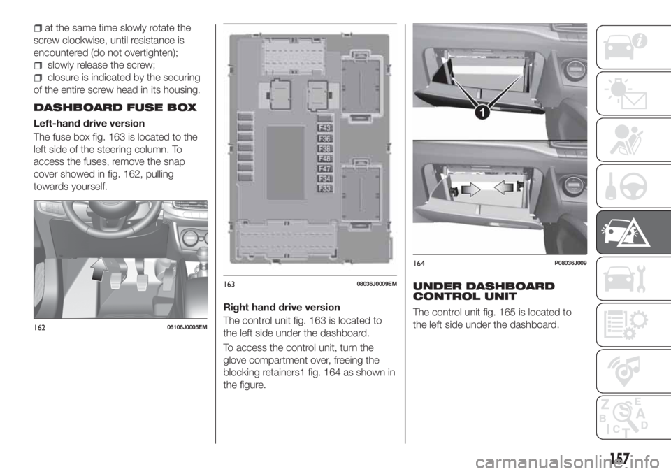
The fuse box fig. 163 is located to the
left side of the steering column. To
access the fuses, remove the snap
cover showed in fig. 162, pulling
towards yourself.
Right hand drive version
The control unit fig. 163 is located to
the left side under the dashboard.
To access the control unit, turn the
glove compartment over, freeing the
blocking retainers1 fig. 164 as shown in
the figure.
UNDER DASHBOARD
CONTROL UNIT
The control unit fig. 165 is located to
the left side under the dashboard.
16206106J0005EM
16308036J0009EM
164P08036J009
157
Page 162 of 304
DASHBOARD FUSE BOX
fig. 163
USERSFUSE AMPERE
Front electric window (driver side) F47 25
Front electric window (passenger side) F48 25
Supply forUconnect
™system, Climate Control system, EOBD
system, USB/AUX port (where provided), steering wheel
controls.F36 15
Dead Lock device (Driver side door unlocking for
versions/markets, where provided)/Door unlocking/Central
locking/Electric tailgate unlockingF38 20
Windscreen washer pump F43 20
Rear left electric window F33 25
Rear right electric window F34 25
UNDER DASHBOARD CONTROL UNIT
fig. 165
USERSFUSE AMPERE
Front door unlocking (driver side) 1 7.5
Front door unlocking (passenger side) 2 7.5
Rear door unlocking (left) 3 7.5
Rear door unlocking (right) 4 7.5
160
IN AN EMERGENCY
Page 168 of 304
154)Observe the following instructions if
the car is equipped with a spare wheel
smaller than the normal size (a 16” spare
wheel is provided with 17" and 18" tyres)
or a space-saver spare wheel. The
space-saver wheel (for versions/markets
where provided) is specific to your car, do
not use it on other models, or use the
space-saver wheel of other models on your
car. The space-saver wheel must only be
used in the event of an emergency. Never
use it for more than strictly necessary and
never exceed 80 km/h. "Warning! For
temporary use only! 80 km/h max!”.
Replace with standard wheel as soon as
possible. Never remove or cover the sticker
on the space-saver wheel. Never apply a
wheel cap on a space-saver wheel. The
vehicle's driving characteristics will be
modified with the space-saver wheel fitted.
Avoid violent acceleration and braking,
abrupt steering and fast cornering. The
driving characteristics of the car will be
modified with the space-saver spare wheel
or spare wheel fitted. Avoid violent
acceleration and braking, abrupt steering
and fast cornering. The overall duration of
the space-saver wheel is about 3000 km,
after which the relevant tyre must be
replaced with another one of the same
type. Never install a traditional tyre on a rim
designed to be used as a space-saver
wheel. Have the wheel repaired and refitted
as soon as possible. Using two or more
space-saver spare wheels or spare wheels
at the same time is forbidden. Do not apply
grease to the bolt threads before fitting:
they could come unscrewed.IMPORTANT
65)When turning the jack handle make
sure that it can turn freely without scraping
your hand against the ground. The moving
components of the jack ("worm screw" and
joints) can also cause injuries: avoid
touching them. If you come into contact
with lubricating grease, clean yourself
thoroughly.
66)Contact a Fiat Dealership as soon as
possible to have the correct tightening of
the wheel bolts checked.
FIX&GO KIT
(where provided)
155) 156)
67)
DESCRIPTION
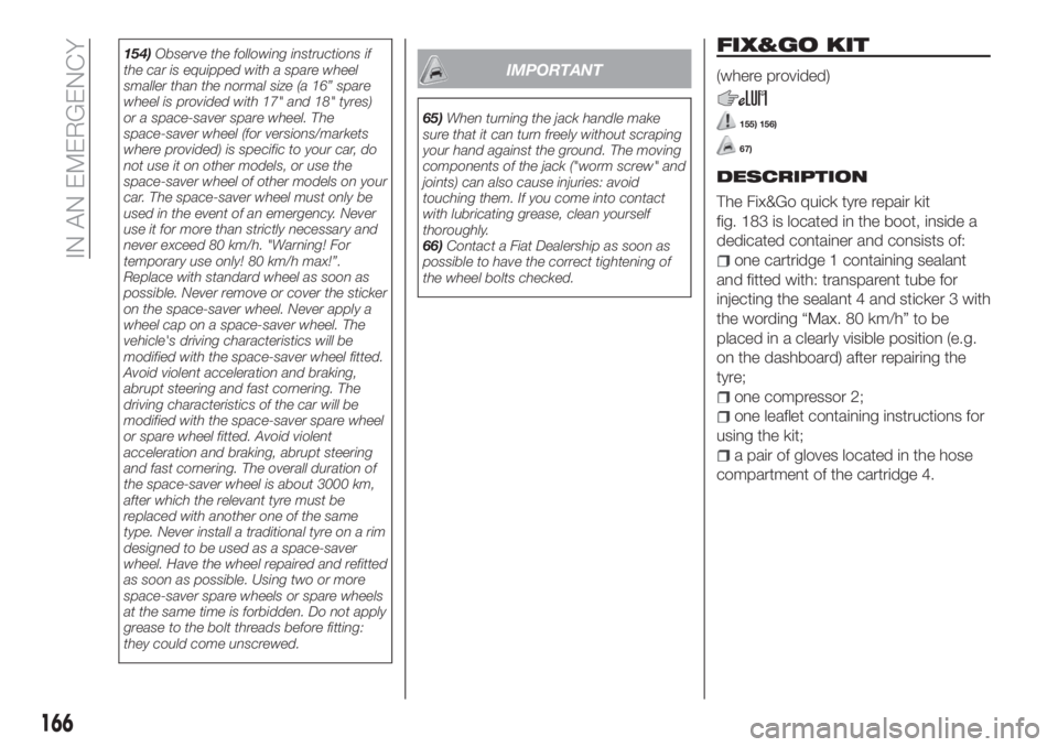
The Fix&Go quick tyre repair kit
fig. 183 is located in the boot, inside a
dedicated container and consists of:
one cartridge 1 containing sealant
and fitted with: transparent tube for
injecting the sealant 4 and sticker 3 with
the wording “Max. 80 km/h” to be
placed in a clearly visible position (e.g.
on the dashboard) after repairing the
tyre;
one compressor 2;
one leaflet containing instructions for
using the kit;
a pair of gloves located in the hose
compartment of the cartridge 4.
166
IN AN EMERGENCY
Page 176 of 304
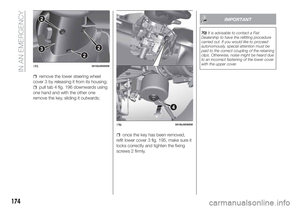
remove the lower steering wheel
cover 3 by releasing it from its housing;
pull tab 4 fig. 196 downwards using
one hand and with the other one
remove the key, sliding it outwards;
once the key has been removed,
refit lower cover 3 fig. 195, make sure it
locks correctly and tighten the fixing
screws 2 firmly.
IMPORTANT
70)It is advisable to contact a Fiat
Dealership to have the refitting procedure
carried out. If you would like to proceed
autonomously, special attention must be
paid to the correct coupling of the retaining
clips. Otherwise, noise might be heard due
to an incorrect fastening of the lower cover
with the upper cover.
19508106J0005EM
19608106J0006EM
174
IN AN EMERGENCY
Page 177 of 304
DUAL-CLUTCH
AUTOMATIC
TRANSMISSION
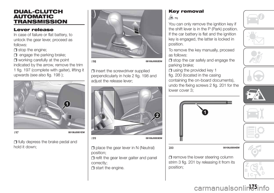
Lever release
In case of failure or flat battery, to
unlock the gear lever, proceed as
follows:
stop the engine;
engage the parking brake;
working carefully at the point
indicated by the arrow, remove the trim
1 fig. 197 (complete with gaiter), lifting it
upwards (see also fig. 198 );
fully depress the brake pedal and
hold it down;
insert the screwdriver supplied
perpendicularly in hole 2 fig. 198 and
adjust the release lever;
place the gear lever in N (Neutral)
position;
refit the gear lever gaiter and panel
correctly;
start the engine.
Key removal
71)
You can only remove the ignition key if
the shift lever is in the P (Park) position.
If the car battery is flat and the ignition
key is engaged, the latter is locked in
position.
To remove the key manually, proceed
as follows:
stop the car safely and engage the
parking brake;
using the provided key 1
fig. 200 (located in the casing
containing the on-board documents),
undo the fixing screws 2 fig. 201 for the
lower cover 3;
remove the lower steering column
strim 3 fig. 201 by releasing it from its
position;
19708106J0001EM
19808106J0002EM
19908106J0003EM
20008106J0004EM
175
Page 179 of 304
WARNING
162)Before towing, turn the key to MAR
and then to STOP without extracting it. The
steering column will automatically lock
when the key is removed and the wheels
cannot be steered. Also check that the
gearbox is in neutral (on versions equipped
with automatic transmission (if present),
check that the gear lever is in N position).163)The brake servo and the
electromechanical power steering will not
work while the vehicle is being towed. You
will therefore need to apply more force on
the brake pedal and steering wheel. Do not
use flexible ropes when towing, and avoid
jerky movements. While towing, make sure
that the trailer hitch does not damage any
components it is touching. When towing
the car, you must comply with all specific
traffic regulations and adopt an appropriate
driving behaviour. Do not start the engine
while towing the vehicle. Before tightening
the ring, clean the threaded housing
thoroughly. Make sure that the ring is fully
screwed into the housing before towing the
car.
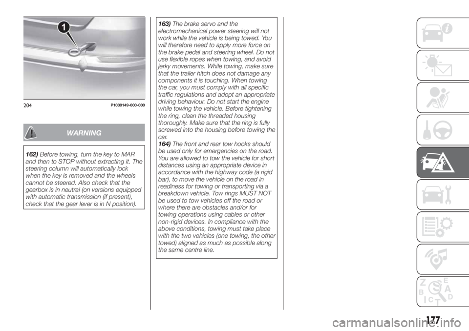
164)The front and rear tow hooks should
be used only for emergencies on the road.
You are allowed to tow the vehicle for short
distances using an appropriate device in
accordance with the highway code (a rigid
bar), to move the vehicle on the road in
readiness for towing or transporting via a
breakdown vehicle. Tow rings MUST NOT
be used to tow vehicles off the road or
where there are obstacles and/or for
towing operations using cables or other
non-rigid devices. In compliance with the
above conditions, towing must take place
with the two vehicles (one towing, the other
towed) aligned as much as possible along
the same centre line.
204P1030149-000-000
177
Page 203 of 304
AUTOMATIC
TRANSMISSION / DUAL
CLUTCH AUTOMATIC
TRANSMISSION
ACTUATION SYSTEM OIL
(where provided)
4)
The transmission control oil level should
only be checked at a Fiat Dealership.
BATTERY
173) 174) 175)
76)
5)
The battery does not require the
electrolyte to be topped up with distilled
water.
A periodic check carried out at a Fiat
Dealership is, however, necessary to
check efficiency.
Replacing the battery
If necessary, replace the battery with
another original battery with the same
specifications. Follow the battery
Manufacturer’s instructions for
maintenance.
USEFUL ADVICE FOR
EXTENDING THE LIFE OF
YOUR BATTERY
Useful advice for extending the life
of your battery
To avoid draining your battery and
make it last longer, observe the
following instructions:
when you park the car, ensure that
the doors, tailgate and bonnet are
closed properly, to prevent any lights
from remaining on inside the
passenger's compartment;
switch off all roof lights inside the car:
the car is however equipped with a
system which switches all internal lights
off automatically;
do not keep accessories (e.g. radio,
hazard warning lights, etc.) switched on
for a long time when the engine is not
running;
before performing any operation on
the electrical system, disconnect the
negative battery cable.
If, after purchasing the vehicle, you wish
to install electrical accessories which
require permanent electrical supply (e.g.
alarm, etc.) or accessories which
influence the electrical supply
requirements, contact a Fiat Dealership,
whose qualified staff will evaluate the
overall electrical consumption.
78)
IMPORTANT After the battery is
disconnected, the steering must be
initialised. The
warning light on the
instrument panel (or symbol on the
display) switches on to indicate this. To
carry out this procedure, simply turn the
steering wheel all the way from one end
to the other or drive in a straight line for
about a hundred metres.
IMPORTANT If the charge level remains
under 50% for a long time, the battery
is damaged by sulphation, reducing its
capacity and efficiency at start-up. The
battery is also more prone to the risk of
freezing (at temperatures as high as
-10°C). Refer to the "Vehicle inactivity"
paragraph in "Starting and driving"
chapter if the vehicle is left parked for a
long time.
WARNING
165)Never smoke while working in the
engine compartment: gas and inflammable
vapours may be present, with the risk of
fire.
166)Be very careful when working in the
engine compartment when the engine is
hot: you may get burned. Do not get too
close to the radiator cooling fan: the
electric fan may start; danger of injury.
Scarves, ties and other loose clothing
might be pulled by moving parts.
201
Page 226 of 304
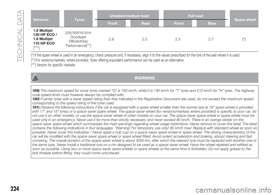
Versions TyresUnladen/medium load Full load
Spare wheel
Front Rear Front Rear
1.6 Multijet
120 HP ECO /
1.6 Multijet
115 HP ECO
(***)
205/55R16 91H
Goodyear
EfficientGrip
Performance
(**)
2.8 2.5 2.5 2.7(*)
(***) Version for specific markets (**) For versions/markets, where provided. Tyres offering equivalent performance can be used as an alternative. (*) If the spare wheel is used in an emergency, check pressure and, if necessary, align it to the values prescribed for the tyre of the axle where it is used
.
WARNING
189)The maximum speed for snow tyres marked “Q” is 160 km/h, while it is 190 km/h for “T” tyres and 210 km/h for "H" tyres. The highway
code speed limits must however always be complied with.
190)If winter tyres with a lower speed rating than that indicated in the Registration Document are used, do not exceed the maximum speed
corresponding to the speed rating of the tyres used.
191)Observe the following instructions if the car is equipped with a spare wheel smaller than the normal size (a 16” spare wheel is provided
with 17" and 18" tyres) or a space-saver spare wheel. The space-saver wheel (for versions/markets where provided) is specific to your car, do
not use it on other models, or use the space-saver wheel of other models on your car. The space-saver spare wheel or spare wheel must be
used only in an emergency. Never use it for more than strictly necessary and never exceed 80 km/h. There is an orange sticker on the
space-saver spare wheel which summarises the main warnings regarding wheel usage restrictions. Never remove or cover the label. The label
contains the following indications in four languages: "Warning! For temporary use only! 80 km/h max! Replace with standard wheel as soon as
possible. Never cover this indication." Never apply a hub cup on a space-saver spare wheel or spare wheel. The driving characteristics of the
car will be modified with the space-saver spare wheel or spare wheel fitted. Avoid violent acceleration and braking, abrupt steering and fast
cornering. The overall duration of the space-saver wheel is about 3000 km, after which the relevant tyre must be replaced with another one of
the same type. Never install a traditional tyre on a rim designed to be used as a space-saver wheel. Have the wheel repaired and refitted as
soon as possible. Using two or more space-saver spare wheels or spare wheels at the same time is forbidden. Do not apply grease to the
bolt threads before fitting: they could come unscrewed.
224
TECHNICAL DATA