bulb FIAT TIPO 5DOORS STATION WAGON 2020 Owner handbook (in English)
[x] Cancel search | Manufacturer: FIAT, Model Year: 2020, Model line: TIPO 5DOORS STATION WAGON, Model: FIAT TIPO 5DOORS STATION WAGON 2020Pages: 304, PDF Size: 9.12 MB
Page 27 of 304
"Lane change" function
To indicate a change of lane with the
car moving, move the left lever to the
non-stable position for less than half a
second.
The direction indicator on the side
selected will be activated for 5 flashes
and then go out automatically.
COURTESY LIGHTS
This function, with the ignition device in
MAR, allows activating the side lights
and the number plate lights for
25 seconds, whenever the car is
unlocked with the key with remote
control.
Enabling the function can be adjusted
through the display Menu or the
Uconnect™system.
The function is automatically disabled
once the activation time elapses
(25 seconds), or when the car doors
are locked again, or by turning the
ignition device to a non-MAR position.
"FOLLOW ME HOME"
DEVICE
Activation
Bring the ignition device to STOP.
Within 2 minutes pull the left stalk in
main beam headlights flashing mode,
each displacement of the stalk will
correspond to an increment of
30 seconds of delay on headlightsswitching off up to a maximum of
210 seconds (equal to 7 flashes).
Deactivation
Keep the left stalk in main beam
headlight flashing mode for a few
seconds.
WARNING
20)The daytime running lights are an
alternative to the dipped headlights for
driving during the daytime in countries
where it is compulsory to have lights on
during the day; where it is not compulsory,
the use of daytime running lights is
permitted.
21)Daytime running lights cannot replace
dipped beam headlights when driving at
night or through tunnels. The use of
daytime running lights is governed by the
highway code of the country in which you
are driving. Comply with legal
requirements.
INTERIOR LIGHTS
FRONT CEILING LIGHT
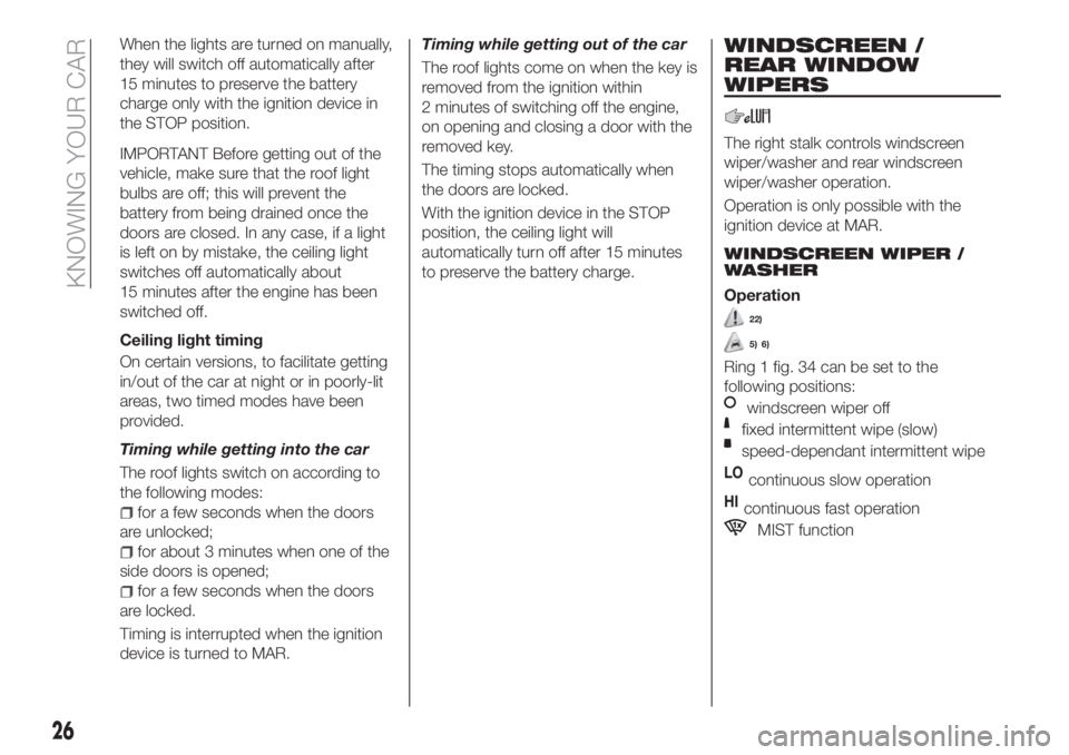
Switch 1 fig. 33 is used to switch on/off
the ceiling light bulbs.
Switch 1 positions:
central position: lights 2 and 5 switch
on/off when the doors are
opened/closed;
pressed to the left (OFF): lights 2 and
5 are always switched off;
pressed to the right (): lights
2 and 5 are always switched on.
The lights switch on/off gradually.
Switch 3 switches on/off light 2.
Switch 4 switches on/off light 5.
3304136J0001EM
25
Page 28 of 304
When the lights are turned on manually,
they will switch off automatically after
15 minutes to preserve the battery
charge only with the ignition device in
the STOP position.
IMPORTANT Before getting out of the
vehicle, make sure that the roof light
bulbs are off; this will prevent the
battery from being drained once the
doors are closed. In any case, if a light
is left on by mistake, the ceiling light
switches off automatically about
15 minutes after the engine has been
switched off.
Ceiling light timing
On certain versions, to facilitate getting
in/out of the car at night or in poorly-lit
areas, two timed modes have been
provided.
Timing while getting into the car
The roof lights switch on according to
the following modes:
for a few seconds when the doors
are unlocked;
for about 3 minutes when one of the
side doors is opened;
for a few seconds when the doors
are locked.
Timing is interrupted when the ignition
device is turned to MAR.Timing while getting out of the car
The roof lights come on when the key is
removed from the ignition within
2 minutes of switching off the engine,
on opening and closing a door with the
removed key.
The timing stops automatically when
the doors are locked.
With the ignition device in the STOP
position, the ceiling light will
automatically turn off after 15 minutes
to preserve the battery charge.
WINDSCREEN /
REAR WINDOW
WIPERS
The right stalk controls windscreen
wiper/washer and rear windscreen
wiper/washer operation.
Operation is only possible with the
ignition device at MAR.
WINDSCREEN WIPER /
WASHER
Operation
22)
5) 6)
Ring 1 fig. 34 can be set to the
following positions:
windscreen wiper off
fixed intermittent wipe (slow)
speed-dependant intermittent wipe
LOcontinuous slow operation
HIcontinuous fast operation
MIST function
26
KNOWING YOUR CAR
Page 71 of 304
Symbol What it means
amberEXTERIOR LIGHTS FAILURE
The symbol switches on to indicate a failure on the following lights: daytime running lights
(DRLs); parking lights; side lights; direction indicators; rear fog light; reversing light; number
plate lights.
The anomaly may be caused by a blown bulb, a blown protection fuse or an interruption of the
electrical connection.
amberFUEL LEVEL SENSOR FAILURE
The symbol switches on in the event of fuel level sensor failure. Contact a Fiat Dealership.
amberLPG FUEL LEVEL SENSOR FAILURE
The symbol switches on in the event of LPG fuel level sensor failure. Contact a Fiat Dealership.
amberPOSSIBLE ICE ON ROAD
The symbol turns on when the outside temperature falls to or below 3°C.
IMPORTANT In the event of outside temperature sensor failure, the digits that indicate the value
are replaced by dashes.
amberDUSK SENSOR FAILURE
The symbol switches on along with a message on the display in the event of dusk sensor
failure. Contact a Fiat Dealership as soon as possible.
amberAUDIO SYSTEM FAILURE
The symbol switches on to report a failure of the audio system. Contact a Fiat Dealership as
soon as possible.
69
Page 147 of 304
IN AN EMERGENCY
A punctured tyre or a burnt-out bulb?
At times, a problem may interfere with
our journey.
The pages on emergencies can help
you to deal with critical situations
independently and with calm.
In an emergency we recommend that
you call the freephone number found in
the Warranty Booklet.
It is also possible to call the national or
international universal freephone
number to search for the nearest Fiat
Dealership.HAZARD WARNING LIGHTS.....146
BULB REPLACEMENT.........146
REPLACING FUSES..........155
CHANGING A WHEEL.........162
FIX&GO KIT................166
JUMP STARTING............169
FUEL CUT-OFF SYSTEM.......171
AUTOMATIC TRANSMISSION. . . .173
DUAL-CLUTCH AUTOMATIC
TRANSMISSION............175
TOWING THE VEHICLE........176
145
Page 148 of 304
HAZARD WARNING
LIGHTS
CONTROL
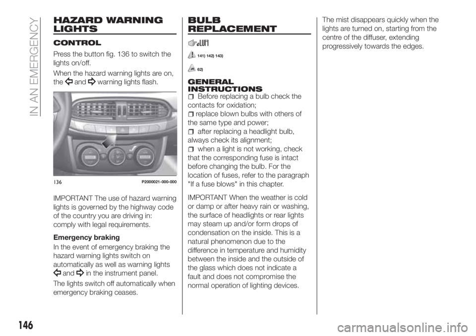
Press the button fig. 136 to switch the
lights on/off.
When the hazard warning lights are on,
the
andwarning lights flash.
IMPORTANT The use of hazard warning
lights is governed by the highway code
of the country you are driving in:
comply with legal requirements.
Emergency braking
In the event of emergency braking the
hazard warning lights switch on
automatically as well as warning lights
andin the instrument panel.
The lights switch off automatically when
emergency braking ceases.
BULB
REPLACEMENT
141) 142) 143)
62)
GENERAL
INSTRUCTIONS
Before replacing a bulb check the
contacts for oxidation;
replace blown bulbs with others of
the same type and power;
after replacing a headlight bulb,
always check its alignment;
when a light is not working, check
that the corresponding fuse is intact
before changing the bulb. For the
location of fuses, refer to the paragraph
"If a fuse blows" in this chapter.
IMPORTANT When the weather is cold
or damp or after heavy rain or washing,
the surface of headlights or rear lights
may steam up and/or form drops of
condensation on the inside. This is a
natural phenomenon due to the
difference in temperature and humidity
between the inside and the outside of
the glass which does not indicate a
fault and does not compromise the
normal operation of lighting devices.The mist disappears quickly when the
lights are turned on, starting from the
centre of the diffuser, extending
progressively towards the edges.
136P2000021-000-000
146
IN AN EMERGENCY
Page 149 of 304
BULBS TYPES
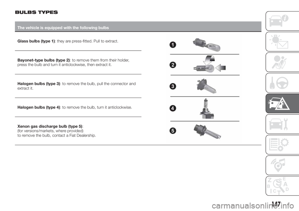
The vehicle is equipped with the following bulbs
Glass bulbs (type 1): they are press-fitted. Pull to extract.
Bayonet-type bulbs (type 2): to remove them from their holder,
press the bulb and turn it anticlockwise, then extract it.
Halogen bulbs (type 3): to remove the bulb, pull the connector and
extract it.
Halogen bulbs (type 4): to remove the bulb, turn it anticlockwise.
Xenon gas discharge bulb (type 5):
(for versions/markets, where provided)
to remove the bulb, contact a Fiat Dealership.
147
Page 150 of 304
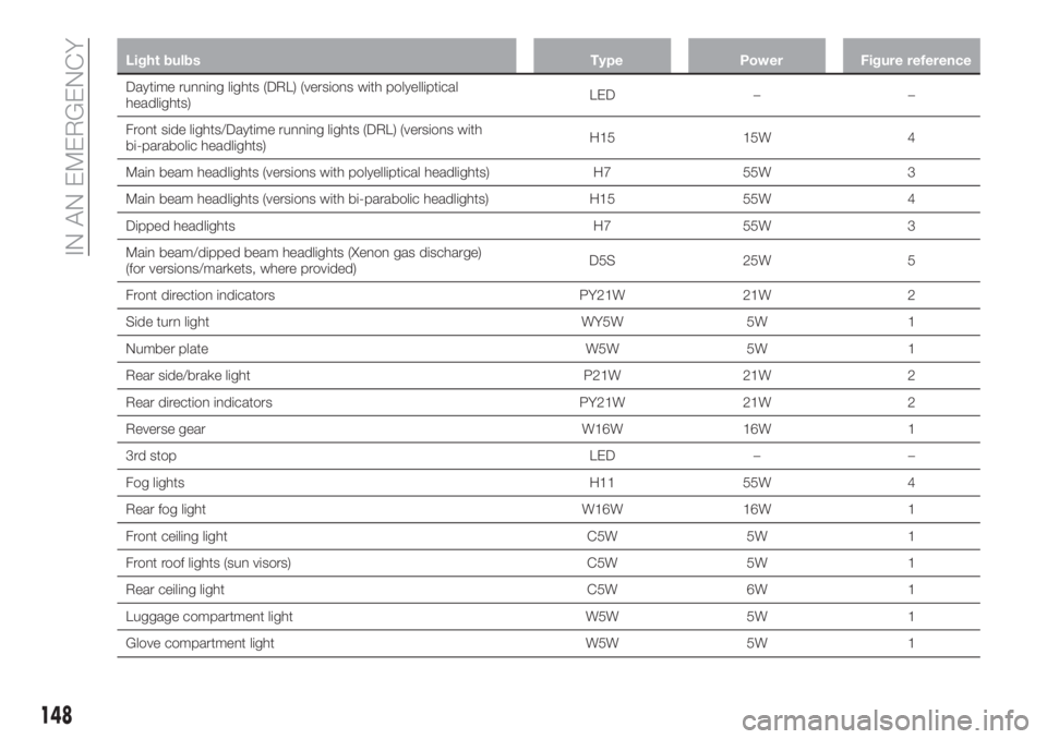
Light bulbs Type Power Figure reference
Daytime running lights (DRL) (versions with polyelliptical
headlights)LED – –
Front side lights/Daytime running lights (DRL) (versions with
bi-parabolic headlights)H15 15W 4
Main beam headlights (versions with polyelliptical headlights) H7 55W 3
Main beam headlights (versions with bi-parabolic headlights) H15 55W 4
Dipped headlights H7 55W 3
Main beam/dipped beam headlights (Xenon gas discharge)
(for versions/markets, where provided)D5S 25W 5
Front direction indicators PY21W 21W 2
Side turn light WY5W 5W 1
Number plate W5W 5W 1
Rear side/brake light P21W 21W 2
Rear direction indicators PY21W 21W 2
Reverse gear W16W 16W 1
3rd stop LED – –
Fog lights H11 55W 4
Rear fog light W16W 16W 1
Front ceiling light C5W 5W 1
Front roof lights (sun visors) C5W 5W 1
Rear ceiling light C5W 6W 1
Luggage compartment light W5W 5W 1
Glove compartment light W5W 5W 1
148
IN AN EMERGENCY
Page 151 of 304
REPLACING AN
EXTERNAL BULB
Versions with poly-elliptical
headlights
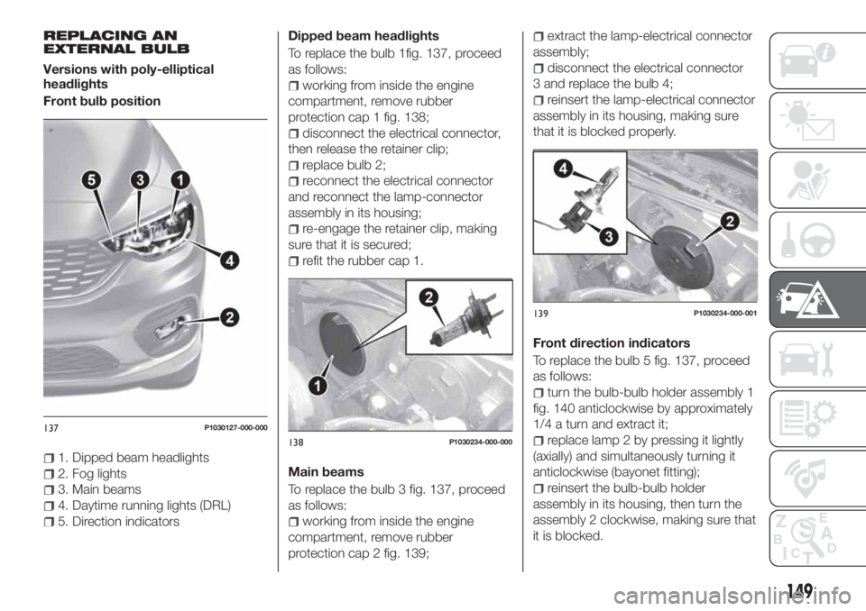
Front bulb position
1. Dipped beam headlights
2. Fog lights
3. Main beams
4. Daytime running lights (DRL)
5. Direction indicatorsDipped beam headlights
To replace the bulb 1fig. 137, proceed
as follows:
working from inside the engine
compartment, remove rubber
protection cap 1 fig. 138;
disconnect the electrical connector,
then release the retainer clip;
replace bulb 2;
reconnect the electrical connector
and reconnect the lamp-connector
assembly in its housing;
re-engage the retainer clip, making
sure that it is secured;
refit the rubber cap 1.
Main beams
To replace the bulb 3 fig. 137, proceed
as follows:
working from inside the engine
compartment, remove rubber
protection cap 2 fig. 139;
extract the lamp-electrical connector
assembly;
disconnect the electrical connector
3 and replace the bulb 4;
reinsert the lamp-electrical connector
assembly in its housing, making sure
that it is blocked properly.
Front direction indicators
To replace the bulb 5 fig. 137, proceed
as follows:
turn the bulb-bulb holder assembly 1
fig. 140 anticlockwise by approximately
1/4 a turn and extract it;
replace lamp 2 by pressing it lightly
(axially) and simultaneously turning it
anticlockwise (bayonet fitting);
reinsert the bulb-bulb holder
assembly in its housing, then turn the
assembly 2 clockwise, making sure that
it is blocked.
137P1030127-000-000
138P1030234-000-000
139P1030234-000-001
149
Page 152 of 304
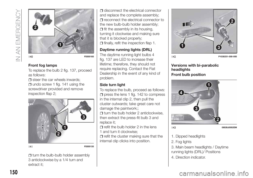
Front fog lamps
To replace the bulb 2 fig. 137, proceed
as follows:
steer the car wheels inwards;
undo screw 1 fig. 141 using the
screwdriver provided and remove
inspection flap 2;
turn the bulb-bulb holder assembly
3 anticlockwise by a 1/4 turn and
extract it;
disconnect the electrical connector
and replace the complete assembly;
reconnect the electrical connector to
the new bulb-bulb holder assembly;
fit the assembly in its housing,
turning it clockwise and making sure
that it is blocked properly;
finally, refit the inspection flap 1.
Daytime running lights (DRL)
The daytime running light bulbs 4
fig. 137 are LED to increase their
lifetime; therefore, they should not
require replacing. Contact the Fiat
Dealership in the event of any kind of
problem.
Side turn light
To replace the bulb, proceed as follows:
press the lens 1 fig. 142 to compress
in the internal clip 2, then pull the
cluster outwards; take great care not
damage the paintwork;;
turn the bulb holder 2 anticlockwise,
then extract the press-fit bulb 3 and
replace it;
refit the bulb holder 2 in the lens
1 and turn it clockwise;
refit the cluster making sure that the
internal clip clicks into position.Versions with bi-parabolic
headlights
Front bulb position
1. Dipped headlights
2. Fog lights
3. Main beam headlights / Daytime
running lights (DRL)/ Positions
4. Direction indicator.
140P2000185
141P2000135
142P1030251-000-000
14308026J0002EM
150
IN AN EMERGENCY
Page 153 of 304
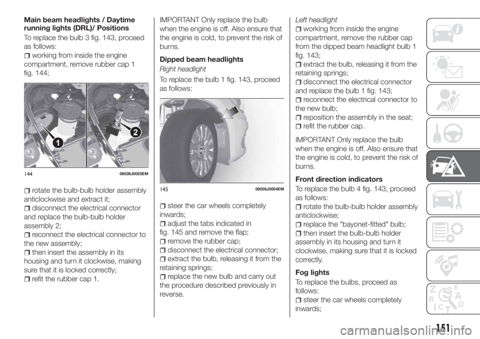
Main beam headlights / Daytime
running lights (DRL)/ Positions
To replace the bulb 3 fig. 143, proceed
as follows:
working from inside the engine
compartment, remove rubber cap 1
fig. 144;
rotate the bulb-bulb holder assembly
anticlockwise and extract it;
disconnect the electrical connector
and replace the bulb-bulb holder
assembly 2;
reconnect the electrical connector to
the new assembly;
then insert the assembly in its
housing and turn it clockwise, making
sure that it is locked correctly;
refit the rubber cap 1.
IMPORTANT Only replace the bulb
when the engine is off. Also ensure that
the engine is cold, to prevent the risk of
burns.
Dipped beam headlights
Right headlight
To replace the bulb 1 fig. 143, proceed
as follows:
steer the car wheels completely
inwards;
adjust the tabs indicated in
fig. 145 and remove the flap;
remove the rubber cap;
disconnect the electrical connector;
extract the bulb, releasing it from the
retaining springs;
replace the new bulb and carry out
the procedure described previously in
reverse.Left headlight
working from inside the engine
compartment, remove the rubber cap
from the dipped beam headlight bulb 1
fig. 143;
extract the bulb, releasing it from the
retaining springs;
disconnect the electrical connector
and replace the bulb 1 fig. 143;
reconnect the electrical connector to
the new bulb;
reposition the assembly in the seat;
refit the rubber cap.
IMPORTANT Only replace the bulb
when the engine is off. Also ensure that
the engine is cold, to prevent the risk of
burns.
Front direction indicators
To replace the bulb 4 fig. 143, proceed
as follows:
rotate the bulb-bulb holder assembly
anticlockwise;
replace the "bayonet-fitted" bulb;
then insert the bulb-bulb holder
assembly in its housing and turn it
clockwise, making sure that it is locked
correctly.
Fog lights
To replace the bulbs, proceed as
follows:
steer the car wheels completely
inwards;
14408026J0025EM
14508026J0004EM
151