brake sensor FIAT UNO 1983 Service Repair Manual
[x] Cancel search | Manufacturer: FIAT, Model Year: 1983, Model line: UNO, Model: FIAT UNO 1983Pages: 303, PDF Size: 10.36 MB
Page 82 of 303
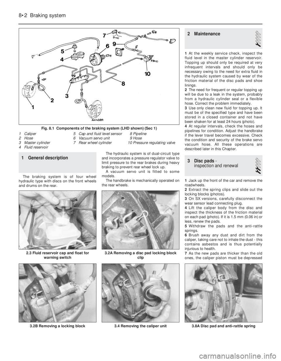
3.4 Removing the caliper unit
1 General description
The braking system is of four wheel
hydraulic type with discs on the front wheels
and drums on the rear.The hydraulic system is of dual-circuit type
and incorporates a pressure regulator valve to
limit pressure to the rear brakes during heavy
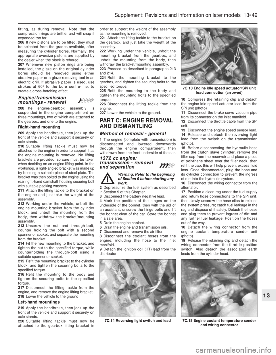
braking to prevent rear wheel lock up.
A vacuum servo unit is fitted to some
models.
The handbrake is mechanically operated on
the rear wheels.
2 Maintenance
1
1At the weekly service check, inspect the
fluid level in the master cylinder reservoir.
Topping up should only be required at very
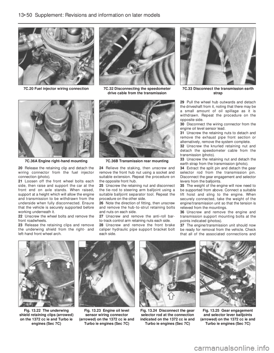
infrequent intervals and should only be
necessary owing to the need for extra fluid in
the hydraulic system caused by wear of the
friction material of the disc pads and shoe
linings.
2The need for frequent or regular topping up
will be due to a leak in the system, probably
from a hydraulic cylinder seal or a flexible
hose. Correct the problem immediately.
3Use only clean new fluid for topping up. lt
must be of the specified type and have been
stored in a closed container and not have
been shaken for at least 24 hours (photo).
4At regular intervals, check the hoses and
pipelines for condition. Adjust the handbrake
if the lever travel becomes excessive. Check
the condition and security of the brake servo
vacuum hose. All these operations are
described later in this Chapter.
3 Disc pads-
inspection and renewal
2
1Jack up the front of the car and remove the
roadwheels.
2Extract the spring clips and slide out the
locking blocks (photos).
3On SX versions, carefully disconnect the
wear sensor lead connecting plug.
4Lift the caliper body from the disc and
inspect the thickness of the friction material
on each pad (photo). If it is 1.5 mm (0.06 in) or
less, renew the pads.
5Withdraw the pads and the anti-rattle
springs.
6Brush away any dust and dirt from the
caliper, taking care not to inhale the dust - this
contains asbestos and is thus potentially
injurious to health.
7As the new pads are thicker than the old
ones, the caliper piston must be depressed
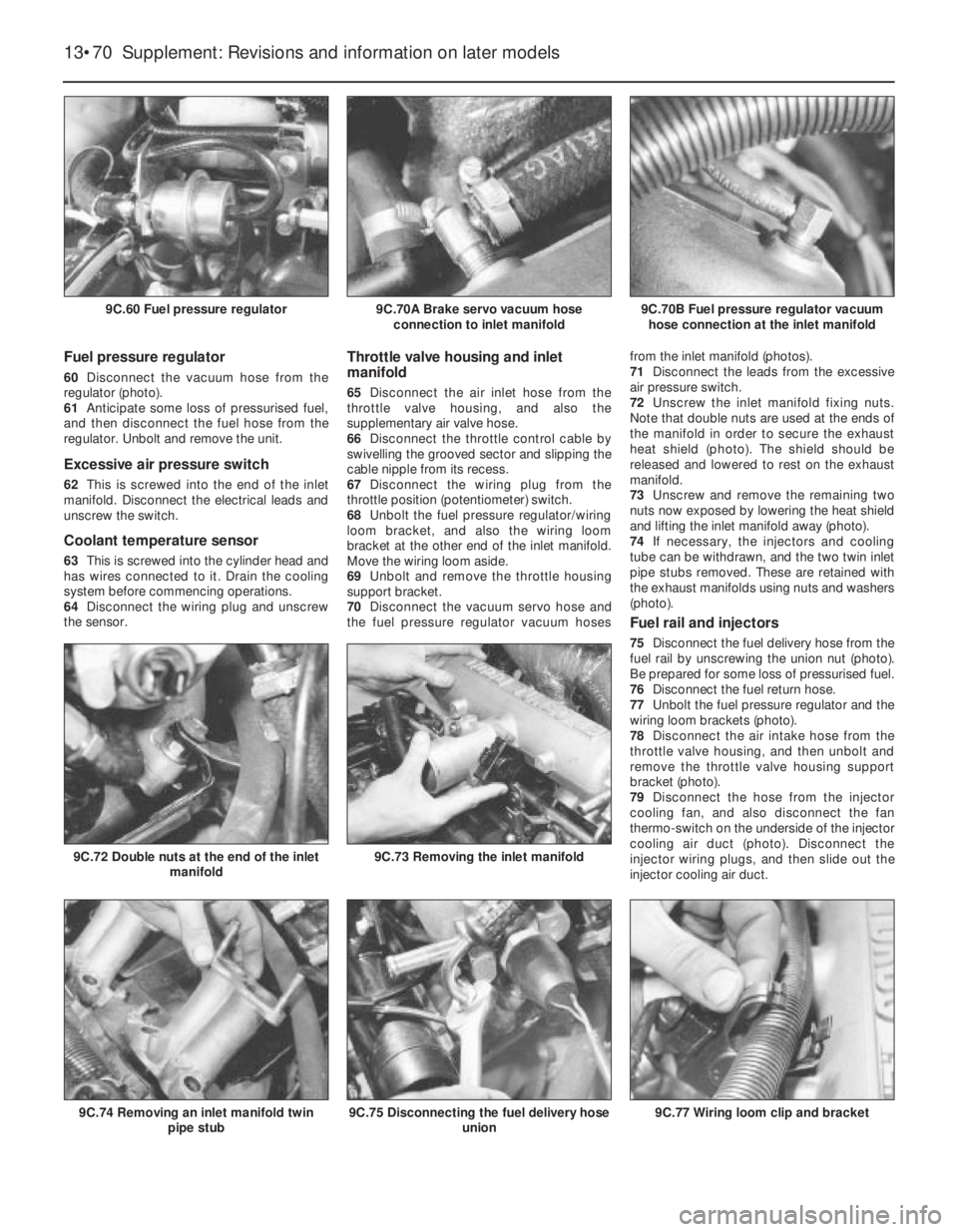
8•2 Braking system
3.8A Disc pad and anti-rattle spring
Fig. 8.1 Components of the braking system (LHD shown) (Sec 1)
1 Caliper
2 Hose
3 Master cylinder
4 Fluid reservoir5 Cap and fluid level sensor
6 Vacuum servo unit
7 Rear wheel cylinder8 Pipeline
9 Hose
10 Pressure regulating valve
3.2B Removing a locking block
3.2A Removing a disc pad locking block
clip2.3 Fluid reservoir cap and float for
warning switch
Page 101 of 303
3The centralised door locking system can
operate independently of the key.
4To gain access to the lock solenoid and
linkage, remove the front door trim panel as
described in Chapter 12.
5Disconnect the battery negative lead.
6Disconnect the electrical wiring plugs from
the solenoid within the door cavity.
7Disconnect the solenoid from the lock lever
by removing the clip.
8Unscrew the two bolts which secure the
solenoid to the door and remove it.
9Renew the solenoid or switch as necessary.
10Refitting is a reversal of removal.
11Refer to Section 10 for details of system
fuses and relays.
33 Economy gauge
(Econometer)
2
1This device is fitted to ES (energy saving)
models and indicates to the driver the fuel
consumption (in litres per 100 km) coupled
with a needle which moves over coloured
sections of a dial to make the driver aware
that his method of driving is either conducive
to high or low fuel consumption. Refer to
Chapter 3, Section 16.
2The device is essentially a vacuum gauge
which also incorporates a warning lamp to
indicate to the driver when a change of gear is
required.
3A fuel cut-out valve (see Chapter 3, Sec-
tion 11) is used in conjunction with the
economy gauge so that when the accelerator
pedal is released during a pre-determined
engine speed range, fuel supply to the engine
is stopped, but resumes when the engine
speed falls below the specified range.
LED (light emitter diode)
4The gearchange indicator will only light up
at engine speeds in excess of 2000 rev/min
for vacuum pressures up to 600 mm Hg in 1st,
2nd and 3rd speed gears and for vacuum
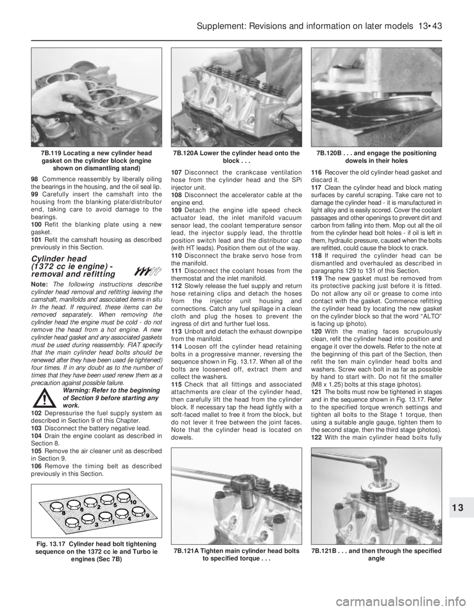
pressures up to 676 mm Hg in 4th speedgear. The light will not come on if 5th speed
gear is engaged or if the coolant temperature
is below 55ºC.
5There is a two second delay in the light
coming on to prevent it operating during rapid
acceleration in a low gear.
6If the LED light comes on during
deceleration it should be ignored.
Fault finding
7A faulty economy gauge should be checked
in the following way.
8Refer to Section 21 and remove the
instrument panel.
9Disconnect the economy gauge L
connector and then connect a test lamp
between the BN cable contact and earth. If
the lamp comes on then the gauge supply
circuit is not open. If the lamp does not come
on, check all connections in the supply cable
which comes from the interconnecting unit of
the electrical system, also Fuse No 12.
10Now connect a voltmeter between the
white cable and earth. Check the voltage with
the engine not running, but the ignition
switched on. It should be between 0.7 and
0.9 volt. If the reading varies considerably
from that specified, check the connections
between the economy gauge and the fuel
cut-out device control unit. If the fault cannot
be rectified, renew the ignition control unit
(Digiplex system, see Chapter 4).
11Now check the closed throttle valve plate
switch by connecting a voltmeter between the
brown and BN cables of the L connector. With
the valve plate open, there should be no
reading, but with it open, voltage should be
indicated.
12Failure to conform as described will be
due to a faulty earth in the switch or a faulty
fuel cut-out device control unit.
13A further test of the throttle valve plate
switch may be carried out by disconnecting
the multi-plug from the fuel cut-out device
control unit.
14Connect a test lamp to contact 4 (positive
battery terminal). The lamp should come on,
when the engine is idling or the accelerator
released. If it does not, renew the throttle
valve plate switch.15Connect a tachometer to the brown/white
cable contact in the L connector and record
the engine speed with the engine running. If
no reading is obtained, renew the Digiplex
ignition control unit which must be faulty.
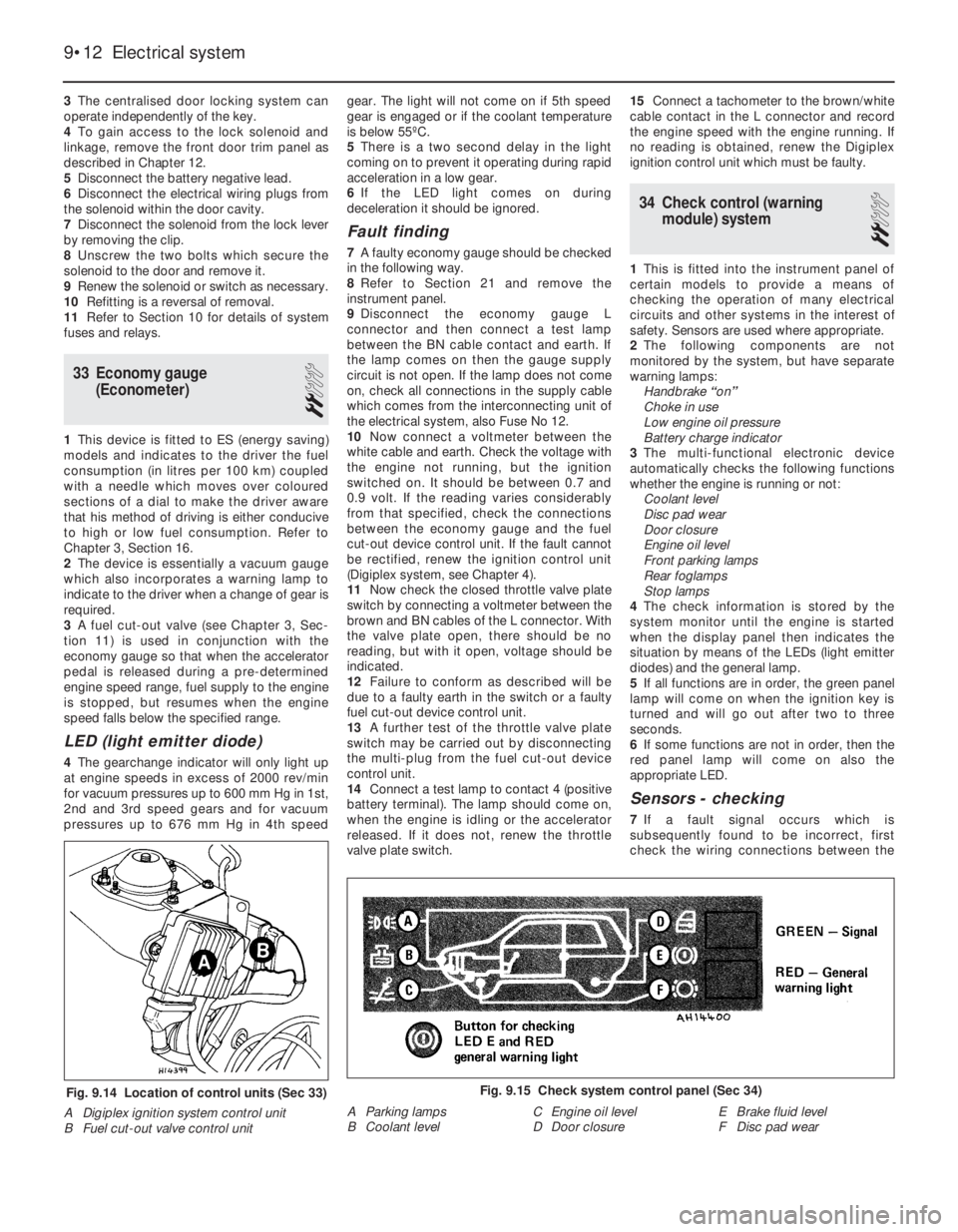
34 Check control (warning
module) system
2
1This is fitted into the instrument panel of
certain models to provide a means of
checking the operation of many electrical
circuits and other systems in the interest of
safety. Sensors are used where appropriate.
2The following components are not
monitored by the system, but have separate
warning lamps:
Handbrake “on”
Choke in use
Low engine oil pressure
Battery charge indicator
3The multi-functional electronic device
automatically checks the following functions
whether the engine is running or not:
Coolant level
Disc pad wear
Door closure
Engine oil level
Front parking lamps
Rear foglamps
Stop lamps
4The check information is stored by the
system monitor until the engine is started
when the display panel then indicates the
situation by means of the LEDs (light emitter
diodes) and the general lamp.
5If all functions are in order, the green panel
lamp will come on when the ignition key is
turned and will go out after two to three
seconds.
6If some functions are not in order, then the
red panel lamp will come on also the
appropriate LED.
Sensors - checking
7If a fault signal occurs which is
subsequently found to be incorrect, first
check the wiring connections between the
9•12 Electrical system
Fig. 9.15 Check system control panel (Sec 34)
A Parking lamps
B Coolant levelC Engine oil level
D Door closureE Brake fluid level
F Disc pad wearFig. 9.14 Location of control units (Sec 33)
A Digiplex ignition system control unit
B Fuel cut-out valve control unit
Page 128 of 303
Braking system................................................................................. 14
Part A: Braking system general
Front brake pads all later models
Part B: Braking system - Turbo ie models
Description
Front disc pads - renewal
Front disc caliper - removal and refitting
Front disc caliper - overhaul
Front brake disc - inspection, renovation or renewal
Rear disc pads - renewal
Rear disc caliper - removal, overhaul and refitting
Rear brake disc - inspection, renovation and renewal
Pressure regulating valve
Brake pedal - removal and refitting
Vacuum servo unit and master cylinder - general
Antiskid system - description
Electrical system.............................................................................. 15
Alternator (999 cc models) - removal and refitting
Alternator (later models) - removal and refitting
Alternator brushes - renewal
Starter motor (999 cc models) - removal and refitting
Starter motor (1301 cc Turbo ie, 1372 cc ie, 1372 cc Turbo ie)
- removal and refitting
Starter motor brushes (later models) - renewal
Fuses - later models
Relays (Turbo ie models) - general
Headlamps - later models
Headlamp beam adjusters for load compensation - later models
Headlamp unit removal - later models
Headlamp dim-dip system - description
Front fog lamps bulb/unit - removal and refitting and beam
adjustment
Horn - relocation
Steering column combination switches (later models) - removal
and refittingInstrument panel (Turbo ie models) - removal and refitting
Facia-mounted switches (1301 cc Turbo ie model) - removal
and refitting
Instrument panel (later models) - removal and refitting
Auxiliary control panel (later models) - removal and refitting
Heater control panel (later models) - removal and refitting
Trip master
Interior roof mounted spotlamp, switch and/or clock - removal
and refitting
Central door locking system
Cigar lighter (later models) - removal and refitting
Electrically operated window switches - removal and refitting
Windscreen wiper motor (later models) - removal and refitting
Windscreen washer reservoir (Turbo) - removal and refitting
Tailgate wiper motor (later models) - removal and refitting
Radio Check control system sensors - description
Check control system sensors - testing
Suspension....................................................................................... 16
Front anti-roll bar - removal and refitting
Suspension strut later models
Bodywork.......................................................................................... 17
Plastic components
Rear view mirrors
Door armrest
Tailgate (Turbo ie model) - component removal and refitting
Radiator grille (1301 cc Turbo ie model) - removal and
refitting
Radiator grille (1372 cc ie and 1372 cc Turbo ie models) -
removal and refitting
Bumpers (1301 cc Turbo ie, 1372 cc ie and 1372 cc Turbo ie
models) - removal and refitting
Rear hinged windows - removal and refitting
Door trim panel (Turbo ie model) - removal and refitting
Supplement: Revisions and information on later models 13•3
13
1 Introduction
Since its introduction in 1983, the FIAT Uno
has had a number of modifications and
improvements including the fitting of a twin
choke carburettor, low profile tyres, tinted
windows and remotely-controlled central door
locking.
The major mechanical change was the
introduction of the FIRE (Fully Integrated
Robotised Engine) on 45 and 45S models to
be followed by a new 1108 cc “FIRE” engine
on the 60S model from 1989 on.
A 1301 cc Turbo ie engine model wasavailable for a short period. This model had a
Bosch LE2 Jetronic electronic fuel injection
(ie) and a turbocharger to give added
performance. To uprate the braking to suit,
disc brakes were fitted to the rear in place of
the original drum type brakes.
A 1372 cc engine model was introduced in
1989. Two versions were initially available. A
Bosch Mono-Jetronic single-point fuel
injection (SPi) system, as found on the 70 SX
model and Bosch L3.1 or L3.2 Jetronic
multi-point fuel injection (MPi) systems were
fitted to Turbo models. L3.2 MPi system
models were equipped with catalytic
converters, to improve exhaust emission. All
fuel injection engines are fitted with electroni-
cally controlled engine management systems.
A new style instrument panel, switchgearand a revised facia layout was introduced in
1989.
During 1992, SPi fuel systems were fitted to
the 999 cc and 1108 cc engines, along with
catalytic converters for improved exhaust
emissions.
Five speed transmissions were introduced
to 999 cc models in 1993.
It is recommended that this Supplement is
always referred to before the main Chapters
of the Manual.
Project vehicles
The vehicles used in the preparation of this
supplement, and appearing in many of the
photographic sequences were a 1986 Uno
45S FIRE, a 1988 1301 cc Uno Turbo ie and a
1991 1372 cc Uno SXie.
Easy,suitable for
novice with little
experienceFairly easy,suitable
for beginner with
some experienceFairly difficult,
suitable for competent
DIY mechanic
Difficult,suitable for
experienced DIY
mechanicVery difficult,
suitable for expert DIY
or professional
Degrees of difficulty
54321
Page 143 of 303
13•18 Supplement: Revisions and information on later models
Every 9000 miles (15 000 km) or
12 months (whichever comes first)
m mCheck the tyre pressures and their condition
(including the spare)
m mWhere a pad wear warning light is fitted, check its
operation
m mCheck the front brake disc pads for excessive wear
m mCheck the underbody condition (fuel and brakes
pipes, exhaust system, hoses, bushes and gaiters)
m mCheck the condition and tension of drivebelts
m mCheck the engine idle speed and CO emissions
m mCheck the EGR system (If fitted)
m mCheck fluid levels (coolant, brake fluid and
windscreen washer)
m mRenew spark plugs (1372 cc Turbo models)
m mRenew the engine oil and oil filter (non-Turbo
models)
m mCheck the HT leads and connections
m mCheck the condition of all coolant, fuel and
hydraulic hoses and connections
Every 18 000 miles (30 000 km) or
24 months (whichever comes first)
In addition to the items listed for 9000 mile (15 000 km) or 12 months
service
m mCheck the rear brake disc pads for wear (where
applicable)
m mCheck/adjust the valve clearances
m mCheck and tighten (if necessary), inlet and exhaust
manifolds
m mCheck the clutch adjustment (cable operated
models)
m mRenew the fuel filter (where applicable)
m mRenew the air cleaner element
m mRenew the spark plugs and check the HT leads
and connections (all models)
m mWhere applicable, have the ignition and injection
systems checked (special equipment needed)
m mRenew coolant
m mRenew brake fluid
Every 28 000 miles (45 000 km) or
36 months (whichever comes first)
In addition to the items listed for 9000 mile (15 000 km) or 12 months
service
m mCheck Lambda (oxygen) sensors operation (special
equipment needed)
m mCheck fuel evaporation system (where fitted)
m mCheck the transmission oil level
m mCheck the condition crankcase ventilation system
Every 37 000 miles (60 000 km) or
48 months (whichever comes first)
In addition to the items listed for 18 000 mile (30 000 km) or
24 months service
m mCheck the condition of the rear brake shoe linings
m mCheck the condition of the timing belt
Every 65 000 miles (105 000 km)
m
mRenew the timing belt
Every 74 500 miles (120 000 km)
m
mRenew the manual transmission oil
Every 250 miles (400 km), weekly or
before a long journey
m mProceed as described for the earlier models at the
start of this manual
Every 6000 miles (10 000 km) or
12 months (whichever comes first)
m mRenew the engine oil and oil filter (Turbo models
only)
3 Routine maintenance- all models from June 1991
The maintenance intervals in this manual are provided with the
assumption that you, not the dealer, will be carrying out the work.
These are the minimum maintenance intervals recommended by us, for
vehicles driven daily. If you wish to keep your vehicle in peak condition
at all times, you may wish to perform some of these procedures more
often. We encourage frequent maintenance, since it enhances the
efficiency, performance and resale value of your vehicle.
If the vehicle is driven in dusty areas, used to tow a trailer, or driven
frequently at slow speeds (idling in traffic) or on short journeys, more
frequent maintenance intervals are recommended.
When the vehicle is new, it should be serviced by an authorised
dealer to preserve the factory warranty.
Page 168 of 303
98Commence reassembly by liberally oiling
the bearings in the housing, and the oil seal lip.
99Carefully insert the camshaft into the
housing from the blanking plate/distributor
end, taking care to avoid damage to the
bearings.
100Refit the blanking plate using a new
gasket.
101Refit the camshaft housing as described
previously in this Section.
Cylinder head
(1372 cc ie engine) -
removal and refitting
#
Note: The following instructions describe
cylinder head removal and refitting leaving the
camshaft, manifolds and associated items in situ
In the head. If required, these items can be
removed separately. When removing the
cylinder head the engine must be cold - do not
remove the head from a hot engine. A new
cylinder head gasket and any associated gaskets
must be used during reassembly. FIAT specify
that the main cylinder head bolts should be
renewed after they have been used (ie tightened)
four times. If in any doubt as to the number of
times that they have been used renew them as a
precaution against possible failure.
Warning: Refer to the beginning
of Section 9 before starting any
work.
102Depressurise the fuel supply system as
described in Section 9 of this Chapter.
103Disconnect the battery negative lead.
104Drain the engine coolant as described in
Section 8.
105Remove the air cleaner unit as described
in Section 9.
106Remove the timing belt as described
previously in this Section.107Disconnect the crankcase ventilation
hose from the cylinder head and the SPi
injector unit.
108Disconnect the accelerator cable at the
engine end.
109Detach the engine idle speed check
actuator lead, the inlet manifold vacuum
sensor lead, the coolant temperature sensor
lead, the injector supply lead, the throttle
position switch lead and the distributor cap
(with HT leads). Position them out of the way.
110Disconnect the brake servo hose from
the manifold.
111Disconnect the coolant hoses from the
thermostat and the inlet manifold.
112Slowly release the fuel supply and return
hose retaining clips and detach the hoses
from the injector unit housing and
connections. Catch any fuel spillage in a clean
cloth and plug the hoses to prevent the
ingress of dirt and further fuel loss.
113Unbolt and detach the exhaust downpipe
from the manifold.
114Loosen off the cylinder head retaining
bolts in a progressive manner, reversing the
sequence shown in Fig. 13.17. When all of the
bolts are loosened off, extract them and
collect the washers.
115Check that all fittings and associated
attachments are clear of the cylinder head,
then carefully lift the head from the cylinder
block. If necessary tap the head lightly with a
soft-faced mallet to free it from the block, but
do not lever it free between the joint faces.
Note that the cylinder head is located on
dowels.116Recover the old cylinder head gasket and
discard it.
117Clean the cylinder head and block mating
surfaces by careful scraping. Take care not to
damage the cylinder head - it is manufactured in
light alloy and is easily scored. Cover the coolant
passages and other openings to prevent dirt and
carbon from falling into them. Mop out all the oil
from the cylinder head bolt holes - if oil is left in
them, hydraulic pressure, caused when the bolts
are refitted, could cause the block to crack.
118If required the cylinder head can be
dismantled and overhauled as described in
paragraphs 129 to 131 of this Section.
119The new gasket must be removed from
its protective packing just before it is fitted.
Do not allow any oil or grease to come into
contact with the gasket. Commence refitting
the cylinder head by locating the new gasket
on the cylinder block so that the word “ALTO”
is facing up (photo).
120With the mating faces scrupulously
clean, refit the cylinder head into position and
engage it over the dowels. Refer to the note at
the beginning of this part of the Section, then
refit the ten main cylinder head bolts and
washers. Screw each bolt in as far as possible
by hand to start with. Do not fit the smaller
(M8 x 1.25) bolts at this stage (photos).
121The bolts must now be tightened in stages
and in the sequence shown in Fig. 13.17. Refer
to the specified torque wrench settings and
tighten all bolts to the Stage 1 torque, then
using a suitable angle gauge, tighten them to
the second stage, then the third stage (photos).
122With the main cylinder head bolts fully
Supplement: Revisions and information on later models 13•43
7B.120B . . . and engage the positioning
dowels in their holes7B.120A Lower the cylinder head onto the
block . . .7B.119 Locating a new cylinder head
gasket on the cylinder block (engine
shown on dismantling stand)
7B.121A Tighten main cylinder head bolts
to specified torque . . .Fig. 13.17 Cylinder head bolt tightening
sequence on the 1372 cc ie and Turbo ie
engines (Sec 7B)
13
7B.121B . . . and then through the specified
angle
Page 174 of 303
fitting, as during removal. Note that the
compression rings are brittle, and will snap if
expanded too far.
206If new pistons are to be fitted, they must
be selected from the grades available, after
measuring the cylinder bores. Normally, the
appropriate oversize pistons are supplied by
the dealer when the block is rebored.
207Whenever new piston rings are being
installed, the glaze on the original cylinder
bores should be removed using either
abrasive paper or a glaze-removing tool in an
electric drill. If abrasive paper is used, use
strokes at 60º to the bore centre-line, to
create a cross-hatching effect.
Engine/transmission
mountings - renewalÁ
208The engine/gearbox assembly is
suspended in the engine compartment on
three mountings, two of which are attached to
the gearbox, and one to the engine.
Right-hand mounting
209Apply the handbrake, then jack up the
front of the vehicle and support it securely on
axle stands.
210Suitable lifting tackle must now be
attached to the engine in order to support it as
the engine mounting is removed. No lifting
brackets are provided, so care must be taken
when deciding on an engine lifting point. In the
workshop, a right-angled bracket was made up
by bending a suitable piece of steel plate. The
bracket was then bolted to the engine using the
rear right-hand camshaft housing securing bolt
with suitable packing washers.
211Attach the lifting tackle to the bracket on
the engine and just take the weight of the
assembly.
212Working under the vehicle, unbolt the
engine mounting bracket from the cylinder
block, and unbolt the mounting from the
body, then withdraw the bracket/mounting
assembly.
213Unscrew the nut and through-bolt,
counter holding the bolt with a second
spanner or socket, and separate the mounting
from the bracket.
214Fit the new mounting to the bracket, and
tighten the nut to the specified torque, while
counterholding the through-bolt using a
suitable spanner or socket.
215Refit the mounting bracket to the cylinder
block, and tighten the securing bolts to the
specified torque.
216Refit the mounting to the body and
tighten the securing bolts to the specified
torque.
217Disconnect the lifting tackle from the
engine, and remove the engine lifting bracket.
218Lower the vehicle to the ground.
Left-hand mountings
219Apply the handbrake, then jack up the
front of the vehicle and support it securely on
axle stands.
220Suitable lifting tackle must now be
attached to the gearbox lifting bracket inorder to support the weight of the assembly
as the mounting is removed.
221Attach the lifting tackle to the bracket on
the gearbox, and just take the weight of the
assembly.
222Working under the vehicle, unbolt the
mounting bracket from the gearbox, and
unbolt the mounting from the body, then
withdraw the bracket/mounting assembly.
223Proceed as described in paragraphs 213
and 214.
224Refit the mounting bracket to the
gearbox, and tighten the securing bolts to the
specified torque.
225Refit the mounting to the body and
tighten the mounting bolts to the specified
torque.
226Disconnect the lifting tackle from the
engine.
227Lower the vehicle to the ground.
PART C: ENGINE REMOVAL
AND DISMANTLING
Method of removal - general
1The engine (complete with transmission) is
disconnected and lowered downwards
through the engine compartment, then
withdrawn from the front underside of the car.
1372 cc engine/
transmission - removal
and separation
#
Warning: Refer to the beginning
of Section 9 before starting any
work.
2Depressurize the fuel system as described
in Section 9 of this Chapter.
3Disconnect the battery negative lead.
4Mark the position of the hinges on the
underside of the bonnet, then with the aid of
an assistant, unscrew the hinge bolts and lift
the bonnet clear of the car. Store the bonnet
in a safe area.
5Drain the engine coolant.
6Drain the engine and transmission oils.
7Disconnect and remove the air filter.
8Disconnect the coolant hoses from the
engine, including the hose to the inlet
manifold.
9Detach the ignition coil (HT) lead from the
distributor.10Compress the retaining clip and detach
the engine idle speed actuator lead from the
SPi unit (photo).
11Disconnect the brake servo vacuum pipe
from its connector on the inlet manifold.
12Disconnect the throttle cable from the SPi
unit.
13Disconnect the engine speed sensor lead.
14Release and detach the reversing light
lead from the switch on the transmission
(photo).
15Before disconnecting the hydraulic hose
from the clutch slave cylinder, remove the
filler cap from the reservoir and place a piece
of polythene sheet over the filler neck, then
refit the cap; this will help prevent excess fluid
loss. Once disconnected, plug the hose and
its cylinder connection to prevent the ingress
of dirt into the hydraulic system.
16Disconnect the wiring connector from the
alternator.
17Position a clean rag under the fuel supply
and return hose connections to the SPi unit,
then slowly unscrew the hose clips to release
the system pressure; catch fuel leakage in the
rag and dispose of it safely. Detach the hoses
and plug them to prevent ingress of dirt and
any further fuel leakage. Position the hoses
out of the way.
18Detach the wiring connector from the
engine coolant temperature sender unit
(photo).
19Release the retaining clip and detach the
wiring connector from the throttle position
switch. Also detach the associated earth
leads from the cylinder head.
Supplement: Revisions and information on later models 13•49
7C.14 Reversing light switch and lead7C.18 Engine coolant temperature sender
and wiring connector
7C.10 Engine idle speed actuator/SPi unit
lead connection (arrowed)
13
Page 175 of 303
20Release the retaining clip and detach the
wiring connector from the fuel injector
connection (photo).
21Loosen off the front wheel bolts each
side, then raise and support the car at the
front end on axle stands. When raised,
support at a height which will allow the engine
and transmission to be withdrawn from the
underside when fully disconnected. Ensure
that the vehicle is securely supported before
working underneath it.
22Unscrew the wheel bolts and remove the
front roadwheels.
23Release the retaining clips and remove
the underwing shield from the right- and
left-hand front wheel arch.24Relieve the staking, then unscrew and
remove the front hub nut using a socket and
suitable extension. Repeat the procedure on
the opposite front hub.
25Unscrew the retaining nut and disconnect
the tie-rod to steering arm balljoint using a
suitable balljoint separator tool. Repeat the
procedure on the other side.
26Note the direction of fitting, then unscrew
and remove the hub-to-strut retaining bolts
and nuts on each side.
27Unscrew and remove the anti-roll bar-
to-track control arm retaining nuts each side.
28Unscrew and remove the front brake
caliper hydraulic pipe support bracket bolt
each side.29Pull the wheel hub outwards and detach
the driveshaft from it, noting that there may be
a small amount of oil spillage as it is
withdrawn. Repeat the procedure on the
opposite side.
30Disconnect the wiring connector from the
engine oil level sensor lead.
31Unscrew the retaining nuts to detach and
remove the exhaust pipe front section or
alternatively, remove the system complete.
32Unscrew the knurled retaining nut and
detach the speedometer cable from the
transmission (photo).
33Unscrew the retaining nut and detach the
earth strap from the transmission (photo).
34Extract the split pin and detach the gear
selector rod from the transmission pin.
Disconnect the gear engagement and selector
levers from the balljoints.
35The weight of the engine will now need to
be supported from above. Connect a suitable
lift hoist and sling to the engine. When
securely connected, take the weight of the
engine/transmission unit so that the tension is
relieved from the mountings.
36Unscrew and remove the engine and
transmission support mounting bolts at the
points indicated (photos).
37The engine/transmission unit should now
be ready for removal from the vehicle. Check
that all of the associated connections and
13•50 Supplement: Revisions and information on later models
Fig. 13.22 The underwing
shield retaining clips (arrowed)
on the 1372 cc ie and Turbo ie
engines (Sec 7C)Fig. 13.25 Gear engagement
and selector lever balljoints
(arrowed) on the 1372 cc ie and
Turbo ie engines (Sec 7C)Fig. 13.23 Engine oil level
sensor wiring connector
(arrowed) on the 1372 cc ie and
Turbo ie engines (Sec 7C)Fig. 13.24 Disconnect the gear
selector rod at the connection
indicated on the 1372 cc ie and
Turbo ie engines (Sec 7C)
7C.33 Disconnect the transmission earth
strap7C.32 Disconnecting the speedometer
drive cable from the transmission7C.20 Fuel injector wiring connection
7C.36B Transmission rear mounting7C.36A Engine right-hand mounting
Page 195 of 303
Fuel pressure regulator
60Disconnect the vacuum hose from the
regulator (photo).
61Anticipate some loss of pressurised fuel,
and then disconnect the fuel hose from the
regulator. Unbolt and remove the unit.
Excessive air pressure switch
62This is screwed into the end of the inlet
manifold. Disconnect the electrical leads and
unscrew the switch.
Coolant temperature sensor
63This is screwed into the cylinder head and
has wires connected to it. Drain the cooling
system before commencing operations.
64Disconnect the wiring plug and unscrew
the sensor.
Throttle valve housing and inlet
manifold
65Disconnect the air inlet hose from the
throttle valve housing, and also the
supplementary air valve hose.
66Disconnect the throttle control cable by
swivelling the grooved sector and slipping the
cable nipple from its recess.
67Disconnect the wiring plug from the
throttle position (potentiometer) switch.
68Unbolt the fuel pressure regulator/wiring
loom bracket, and also the wiring loom
bracket at the other end of the inlet manifold.
Move the wiring loom aside.
69Unbolt and remove the throttle housing
support bracket.
70Disconnect the vacuum servo hose and
the fuel pressure regulator vacuum hosesfrom the inlet manifold (photos).
71Disconnect the leads from the excessive
air pressure switch.
72Unscrew the inlet manifold fixing nuts.
Note that double nuts are used at the ends of
the manifold in order to secure the exhaust
heat shield (photo). The shield should be
released and lowered to rest on the exhaust
manifold.
73Unscrew and remove the remaining two
nuts now exposed by lowering the heat shield
and lifting the inlet manifold away (photo).
74If necessary, the injectors and cooling
tube can be withdrawn, and the two twin inlet
pipe stubs removed. These are retained with
the exhaust manifolds using nuts and washers
(photo).
Fuel rail and injectors
75Disconnect the fuel delivery hose from the
fuel rail by unscrewing the union nut (photo).
Be prepared for some loss of pressurised fuel.
76Disconnect the fuel return hose.
77Unbolt the fuel pressure regulator and the
wiring loom brackets (photo).
78Disconnect the air intake hose from the
throttle valve housing, and then unbolt and
remove the throttle valve housing support
bracket (photo).
79Disconnect the hose from the injector
cooling fan, and also disconnect the fan
thermo-switch on the underside of the injector
cooling air duct (photo). Disconnect the
injector wiring plugs, and then slide out the
injector cooling air duct.
13•70 Supplement: Revisions and information on later models
9C.77 Wiring loom clip and bracket9C.75 Disconnecting the fuel delivery hose
union9C.74 Removing an inlet manifold twin
pipe stub
9C.73 Removing the inlet manifold9C.72 Double nuts at the end of the inlet
manifold
9C.70B Fuel pressure regulator vacuum
hose connection at the inlet manifold9C.70A Brake servo vacuum hose
connection to inlet manifold9C.60 Fuel pressure regulator
Page 202 of 303
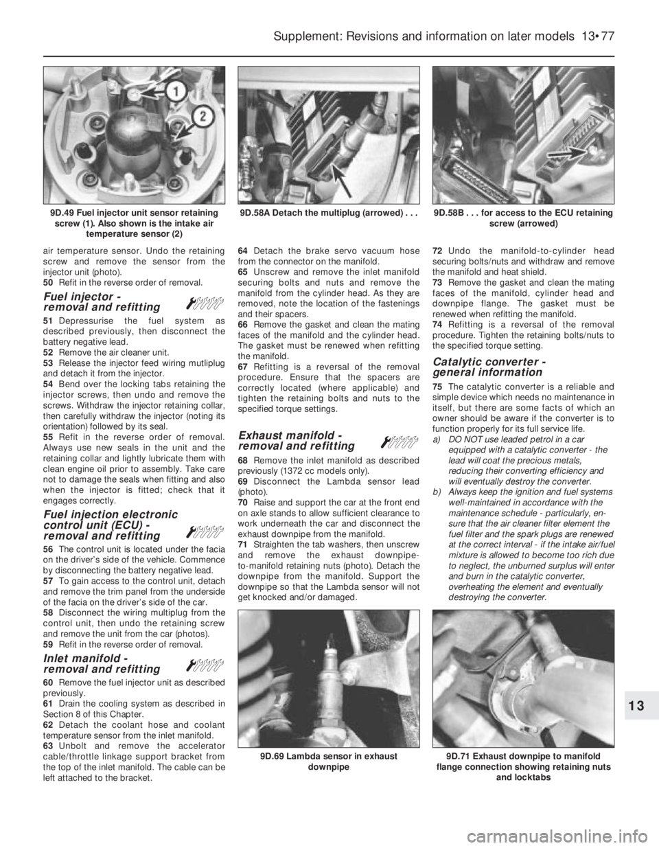
air temperature sensor. Undo the retaining
screw and remove the sensor from the
injector unit (photo).
50Refit in the reverse order of removal.
Fuel injector -
removal and refittingÁ
51Depressurise the fuel system as
described previously, then disconnect the
battery negative lead.
52Remove the air cleaner unit.
53Release the injector feed wiring mutliplug
and detach it from the injector.
54Bend over the locking tabs retaining the
injector screws, then undo and remove the
screws. Withdraw the injector retaining collar,
then carefully withdraw the injector (noting its
orientation) followed by its seal.
55Refit in the reverse order of removal.
Always use new seals in the unit and the
retaining collar and lightly lubricate them with
clean engine oil prior to assembly. Take care
not to damage the seals when fitting and also
when the injector is fitted; check that it
engages correctly.
Fuel injection electronic
control unit (ECU) -
removal and refitting
Á
56The control unit is located under the facia
on the driver’s side of the vehicle. Commence
by disconnecting the battery negative lead.
57To gain access to the control unit, detach
and remove the trim panel from the underside
of the facia on the driver’s side of the car.
58Disconnect the wiring multiplug from the
control unit, then undo the retaining screw
and remove the unit from the car (photos).
59Refit in the reverse order of removal.
Inlet manifold -
removal and refittingÁ
60Remove the fuel injector unit as described
previously.
61Drain the cooling system as described in
Section 8 of this Chapter.
62Detach the coolant hose and coolant
temperature sensor from the inlet manifold.
63Unbolt and remove the accelerator
cable/throttle linkage support bracket from
the top of the inlet manifold. The cable can be
left attached to the bracket.64Detach the brake servo vacuum hose
from the connector on the manifold.
65Unscrew and remove the inlet manifold
securing bolts and nuts and remove the
manifold from the cylinder head. As they are
removed, note the location of the fastenings
and their spacers.
66Remove the gasket and clean the mating
faces of the manifold and the cylinder head.
The gasket must be renewed when refitting
the manifold.
67Refitting is a reversal of the removal
procedure. Ensure that the spacers are
correctly located (where applicable) and
tighten the retaining bolts and nuts to the
specified torque settings.
Exhaust manifold -
removal and refittingÁ
68Remove the inlet manifold as described
previously (1372 cc models only).
69Disconnect the Lambda sensor lead
(photo).
70Raise and support the car at the front end
on axle stands to allow sufficient clearance to
work underneath the car and disconnect the
exhaust downpipe from the manifold.
71Straighten the tab washers, then unscrew
and remove the exhaust downpipe-
to-manifold retaining nuts (photo). Detach the
downpipe from the manifold. Support the
downpipe so that the Lambda sensor will not
get knocked and/or damaged.72Undo the manifold-to-cylinder head
securing bolts/nuts and withdraw and remove
the manifold and heat shield.
73Remove the gasket and clean the mating
faces of the manifold, cylinder head and
downpipe flange. The gasket must be
renewed when refitting the manifold.
74Refitting is a reversal of the removal
procedure. Tighten the retaining bolts/nuts to
the specified torque setting.
Catalytic converter -
general information
75The catalytic converter is a reliable and
simple device which needs no maintenance in
itself, but there are some facts of which an
owner should be aware if the converter is to
function properly for its full service life.
a) DO NOT use leaded petrol in a car
equipped with a catalytic converter - the
lead will coat the precious metals,
reducing their converting efficiency and
will eventually destroy the converter.
b) Always keep the ignition and fuel systems
well-maintained in accordance with the
maintenance schedule - particularly, en-
sure that the air cleaner filter element the
fuel filter and the spark plugs are renewed
at the correct interval - if the intake air/fuel
mixture is allowed to become too rich due
to neglect, the unburned surplus will enter
and burn in the catalytic converter,
overheating the element and eventually
destroying the converter.
Supplement: Revisions and information on later models 13•77
9D.58B . . . for access to the ECU retaining
screw (arrowed)9D.58A Detach the multiplug (arrowed) . . .9D.49 Fuel injector unit sensor retaining
screw (1). Also shown is the intake air
temperature sensor (2)
9D.71 Exhaust downpipe to manifold
flange connection showing retaining nuts
and locktabs9D.69 Lambda sensor in exhaust
downpipe
13
Page 226 of 303
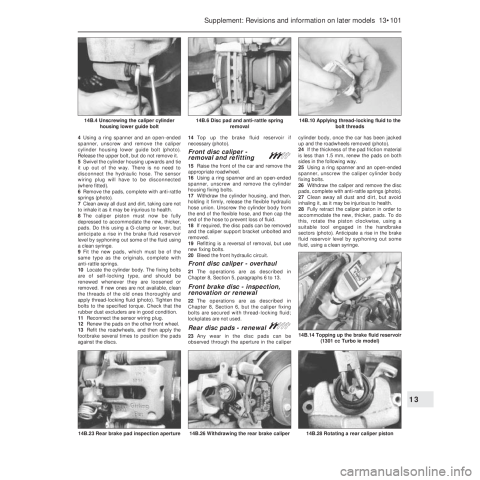
4Using a ring spanner and an open-ended
spanner, unscrew and remove the caliper
cylinder housing lower guide bolt (photo).
Release the upper bolt, but do not remove it.
5Swivel the cylinder housing upwards and tie
it up out of the way. There is no need to
disconnect the hydraulic hose. The sensor
wiring plug will have to be disconnected
(where fitted).
6Remove the pads, complete with anti-rattle
springs (photo).
7Clean away all dust and dirt, taking care not
to inhale it as it may be injurious to health.
8The caliper piston must now be fully
depressed to accommodate the new, thicker,
pads. Do this using a G-clamp or lever, but
anticipate a rise in the brake fluid reservoir
level by syphoning out some of the fluid using
a clean syringe.
9Fit the new pads, which must be of the
same type as the originals, complete with
anti-rattle springs.
10Locate the cylinder body. The fixing bolts
are of self-locking type, and should be
renewed whenever they are loosened or
removed. If new ones are not available, clean
the threads of the old ones thoroughly and
apply thread-locking fluid (photo). Tighten the
bolts to the specified torque. Check that the
rubber dust excluders are in good condition.
11Reconnect the sensor wiring plug.
12Renew the pads on the other front wheel.
13Refit the roadwheels, and then apply the
footbrake several times to position the pads
against the discs.14Top up the brake fluid reservoir if
necessary (photo).
Front disc caliper -
removal and refitting#
15Raise the front of the car and remove the
appropriate roadwheel.
16Using a ring spanner and an open-ended
spanner, unscrew and remove the cylinder
housing fixing bolts.
17Withdraw the cylinder housing, and then,
holding it firmly, release the flexible hydraulic
hose union. Unscrew the cylinder body from
the end of the flexible hose, and then cap the
end of the hose to prevent loss of fluid.
18If required, the disc pads can be removed
and the caliper support bracket unbolted and
removed.
19Refitting is a reversal of removal, but use
new fixing bolts.
20Bleed the front hydraulic circuit.
Front disc caliper - overhaul
21The operations are as described in
Chapter 8, Section 5, paragraphs 6 to 13.
Front brake disc - inspection,
renovation or renewal
22The operations are as described in
Chapter 8, Section 6, but the caliper fixing
bolts are secured with thread-locking fluid;
lockplates are not used.
Rear disc pads - renewal ª
23Any wear in the disc pads can be
observed through the aperture in the calipercylinder body, once the car has been jacked
up and the roadwheels removed (photo).
24If the thickness of the pad friction material
is less than 1.5 mm, renew the pads on both
sides in the following way.
25Using a ring spanner and an open-ended
spanner, unscrew the caliper cylinder body
fixing bolts.
26Withdraw the caliper and remove the disc
pads, complete with anti-rattle springs (photo).
27Clean away all dust and dirt, but avoid
inhaling it, as it may be injurious to health.
28Fully retract the caliper piston in order to
accommodate the new, thicker, pads. To do
this, rotate the piston clockwise, using a
suitable tool engaged in the handbrake
sectors (photo). Anticipate a rise in the brake
fluid reservoir level by syphoning out some
fluid, using a clean syringe.
Supplement: Revisions and information on later models 13•101
14B.10 Applying thread-locking fluid to the
bolt threads14B.6 Disc pad and anti-rattle spring
removal14B.4 Unscrewing the caliper cylinder
housing lower guide bolt
14B.28 Rotating a rear caliper piston14B.26 Withdrawing the rear brake caliper14B.23 Rear brake pad inspection aperture
14B.14 Topping up the brake fluid reservoir
(1301 cc Turbo ie model)
13