jacking points FIAT UNO 1983 Service Repair Manual
[x] Cancel search | Manufacturer: FIAT, Model Year: 1983, Model line: UNO, Model: FIAT UNO 1983Pages: 303, PDF Size: 10.36 MB
Page 5 of 303
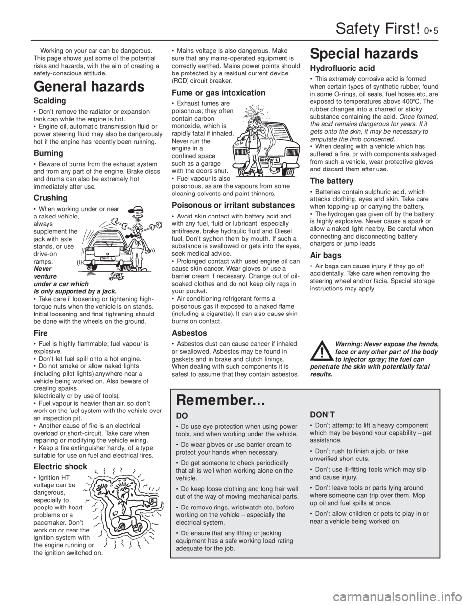
Safety First!0•5
Working on your car can be dangerous.
This page shows just some of the potential
risks and hazards, with the aim of creating a
safety-conscious attitude.
General hazards
Scalding
• Don’t remove the radiator or expansion
tank cap while the engine is hot.
• Engine oil, automatic transmission fluid or
power steering fluid may also be dangerously
hot if the engine has recently been running.
Burning
• Beware of burns from the exhaust system
and from any part of the engine. Brake discs
and drums can also be extremely hot
immediately after use.
Crushing
• When working under or near
a raised vehicle,
always
supplement the
jack with axle
stands, or use
drive-on
ramps.
Never
venture
under a car which
is only supported by a jack.
• Take care if loosening or tightening high-
torque nuts when the vehicle is on stands.
Initial loosening and final tightening should
be done with the wheels on the ground.
Fire
• Fuel is highly flammable; fuel vapour is
explosive.
• Don’t let fuel spill onto a hot engine.
• Do not smoke or allow naked lights
(including pilot lights) anywhere near a
vehicle being worked on. Also beware of
creating sparks
(electrically or by use of tools).
• Fuel vapour is heavier than air, so don’t
work on the fuel system with the vehicle over
an inspection pit.
• Another cause of fire is an electrical
overload or short-circuit. Take care when
repairing or modifying the vehicle wiring.
• Keep a fire extinguisher handy, of a type
suitable for use on fuel and electrical fires.
Electric shock
• Ignition HT
voltage can be
dangerous,
especially to
people with heart
problems or a
pacemaker. Don’t
work on or near the
ignition system with
the engine running or
the ignition switched on.• Mains voltage is also dangerous. Make
sure that any mains-operated equipment is
correctly earthed. Mains power points should
be protected by a residual current device
(RCD) circuit breaker.
Fume or gas intoxication
• Exhaust fumes are
poisonous; they often
contain carbon
monoxide, which is
rapidly fatal if inhaled.
Never run the
engine in a
confined space
such as a garage
with the doors shut.
• Fuel vapour is also
poisonous, as are the vapours from some
cleaning solvents and paint thinners.
Poisonous or irritant substances
• Avoid skin contact with battery acid and
with any fuel, fluid or lubricant, especially
antifreeze, brake hydraulic fluid and Diesel
fuel. Don’t syphon them by mouth. If such a
substance is swallowed or gets into the eyes,
seek medical advice.
• Prolonged contact with used engine oil can
cause skin cancer. Wear gloves or use a
barrier cream if necessary. Change out of oil-
soaked clothes and do not keep oily rags in
your pocket.
• Air conditioning refrigerant forms a
poisonous gas if exposed to a naked flame
(including a cigarette). It can also cause skin
burns on contact.
Asbestos
• Asbestos dust can cause cancer if inhaled
or swallowed. Asbestos may be found in
gaskets and in brake and clutch linings.
When dealing with such components it is
safest to assume that they contain asbestos.
Special hazards
Hydrofluoric acid
• This extremely corrosive acid is formed
when certain types of synthetic rubber, found
in some O-rings, oil seals, fuel hoses etc, are
exposed to temperatures above 400
0C. The
rubber changes into a charred or sticky
substance containing the acid. Once formed,
the acid remains dangerous for years. If it
gets onto the skin, it may be necessary to
amputate the limb concerned.
• When dealing with a vehicle which has
suffered a fire, or with components salvaged
from such a vehicle, wear protective gloves
and discard them after use.
The battery
• Batteries contain sulphuric acid, which
attacks clothing, eyes and skin. Take care
when topping-up or carrying the battery.
• The hydrogen gas given off by the battery
is highly explosive. Never cause a spark or
allow a naked light nearby. Be careful when
connecting and disconnecting battery
chargers or jump leads.
Air bags
• Air bags can cause injury if they go off
accidentally. Take care when removing the
steering wheel and/or facia. Special storage
instructions may apply.
Diesel injection equipment
• Diesel injection pumps supply fuel at very
high pressure. Take care when working on
the fuel injectors and fuel pipes.
Warning: Never expose the hands,
face or any other part of the body
to injector spray; the fuel can
penetrate the skin with potentially fatal
results.
Remember...
DO
• Do use eye protection when using power
tools, and when working under the vehicle.
• Do wear gloves or use barrier cream to
protect your hands when necessary.
• Do get someone to check periodically
that all is well when working alone on the
vehicle.
• Do keep loose clothing and long hair well
out of the way of moving mechanical parts.
• Do remove rings, wristwatch etc, before
working on the vehicle – especially the
electrical system.
• Do ensure that any lifting or jacking
equipment has a safe working load rating
adequate for the job.
A few tips
DON’T
• Don’t attempt to lift a heavy component
which may be beyond your capability – get
assistance.
• Don’t rush to finish a job, or take
unverified short cuts.
• Don’t use ill-fitting tools which may slip
and cause injury.
• Don’t leave tools or parts lying around
where someone can trip over them. Mop
up oil and fuel spills at once.
• Don’t allow children or pets to play in or
near a vehicle being worked on.
Page 8 of 303
0•8Roadside Repairs
To avoid repetition, the procedure for
raising the vehicle, in order to carry out work
under it, is not included before each relevant
operation described in this Manual.
It is to be preferred, and it is certainly
recommended, that the vehicle is positioned
over an inspection pit or raised on a lift. Where
these facilities are not available, use ramps or
jack up the vehicle strictly in accordance with
the following guide. Once the vehicle is raised,
supplement the jack with axle stands.
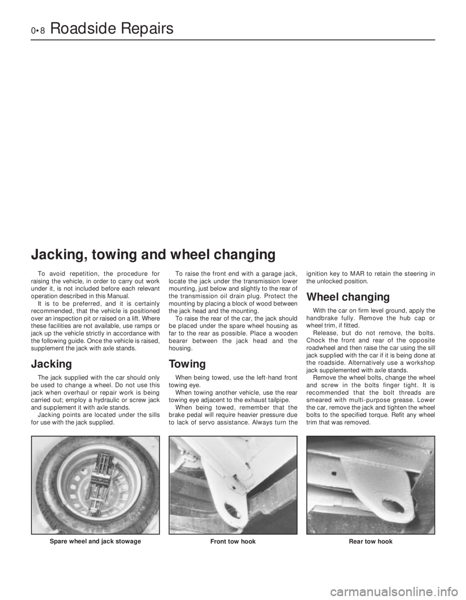
Jacking
The jack supplied with the car should only
be used to change a wheel. Do not use this
jack when overhaul or repair work is being
carried out; employ a hydraulic or screw jack
and supplement it with axle stands.
Jacking points are located under the sills
for use with the jack supplied.To raise the front end with a garage jack,
locate the jack under the transmission lower
mounting, just below and slightly to the rear of
the transmission oil drain plug. Protect the
mounting by placing a block of wood between
the jack head and the mounting.
To raise the rear of the car, the jack should
be placed under the spare wheel housing as
far to the rear as possible. Place a wooden
bearer between the jack head and the
housing.
Towing
When being towed, use the left-hand front
towing eye.
When towing another vehicle, use the rear
towing eye adjacent to the exhaust tailpipe.
When being towed, remember that the
brake pedal will require heavier pressure due
to lack of servo assistance. Always turn theignition key to MAR to retain the steering in
the unlocked position.
Wheel changing
With the car on firm level ground, apply the
handbrake fully. Remove the hub cap or
wheel trim, if fitted.
Release, but do not remove, the bolts.
Chock the front and rear of the opposite
roadwheel and then raise the car using the sill
jack supplied with the car if it is being done at
the roadside. Alternatively use a workshop
jack supplemented with axle stands.
Remove the wheel bolts, change the wheel
and screw in the bolts finger tight. It is
recommended that the bolt threads are
smeared with multi-purpose grease. Lower
the car, remove the jack and tighten the wheel
bolts to the specified torque. Refit any wheel
trim that was removed.
Spare wheel and jack stowage
Front tow hook Rear tow hook
Jacking, towing and wheel changing
Page 38 of 303
5In practice, if several shims have to be
changed, they can often be interchanged, so
avoiding the necessity of having to buy more
new shims than is necessary.
6If more than two or three valve clearances
are found to be incorrect, it will be more
convenient to remove the camshaft carrier for
easier removal of the shims.
7Where no clearance can be measured, even
with the thinnest available shim in position,
the valve will have to be removed and the end
of its stem ground off squarely. This will
reduce its overall length by the minimum
amount to provide a clearance. This job
should be entrusted to your dealer as it is
important to keep the end of the valve stem
square.
8On completion, refit the camshaft cover and
gasket.
27 Camshaft and camshaft
carrier- removal and refitting
3
1Disconnect the battery.
2Remove the air cleaner (see Chapter 3).
3Disconnect the fuel filter hose from the fuel
pump and tie it back, out of the way.
4Identify and then disconnect any electrical
leads which must be moved away to enable
the camshaft cover to be withdrawn.
5Identify and disconnect any vacuum gases
which must be moved away to enable the
camshaft cover to be withdrawn.
6Unscrew the securing nuts and remove the
camshaft cover.
7Turn the crankshaft pulley nut until No. 4
piston is at TDC. This can be established as
described in Section 28.
8Unbolt and remove the timing belt cover.
9Check that the timing mark on the camshaft
sprocket is aligned with, and adjacent to the
pointer on the timing belt cover backplate.
10Restrain the timing belt with the hand and
release but do not remove the camshaft
sprocket bolt. Release the belt tensioner
pulley by slackening the pulley centre nut.
Push the timing belt evenly from the
sprockets, noting which way round the belt isfitted if it is to be completely removed. The
lettering on the belt is normally legible from
the crankshaft pulley end of the engine when
the belt is as originally fitted.
11Unbolt the camshaft carrier and lift it
sufficiently from the cylinder head to break the
seal of the mating faces. Note: It is important
not to allow the cam followers to pull out; they
must be retained in their original locations.
This can be done if the carrier is raised very
slowly, until the fingers can be inserted to
prise the cam followers onto their respective
valve spring retainers. It is unlikely that the
valve clearance adjusting shims will be
displaced from their recesses in the cam
followers because of the suction of the
lubricating oil, but watch that this does not
happen; the shims must also be retained in
their originally fitted sequence.
12Remove the previously loosened
camshaft sprocket bolt and take the sprocket
from the camshaft.
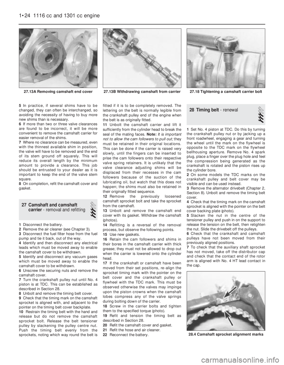
13Unbolt and remove the camshaft end
cover with its gasket. Withdraw the camshaft
(photos).
14Refitting is a reversal of the removal
process, but observe the following points.
15Use new gaskets.
16Retain the cam followers and shims in
their bores in the camshaft carrier with thick
grease; they must not be allowed to drop out
when the carrier is lowered onto the cylinder
head.
17If the crankshaft or camshaft have been
moved from their set positions, re-align the
sprocket timing mark with the pointer on the
belt cover and the crankshaft pulley or
flywheel with the TDC mark. This must be
observed otherwise the valves may impinge
upon the piston crowns when the camshaft
lobes compress any of the valve springs
during bolting down of the carrier.
18Screw in the carrier bolts and tighten
them to the specified torque (photo).
19Refit and tension the timing belt as
described in Section 28.
20Refit the camshaft cover and gasket.
21Refit the hose and air cleaner.
22Reconnect the battery.
28 Timing belt- renewal
3
1Set No. 4 piston at TDC. Do this by turning
the crankshaft pulley nut or by jacking up a
front roadwheel, engaging a gear and turning
the wheel until the mark on the flywheel is
opposite to the TDC mark on the flywheel
bellhousing aperture. Remove No. 4 spark
plug, place a finger over the plug hole and feel
the compression being generated as the
crankshaft is rotated and the piston rises up
the cylinder bore.
2On some models the TDC marks on the
crankshaft pulley and belt cover may be
visible and can be used instead.
3Remove the alternator drivebelt (Chapter 2,
Section 8). Unbolt and remove the timing belt
cover.
4Check that the timing mark on the camshaft
sprocket is aligned with the pointer on the belt
cover backing plate (photo).
5Slacken the nut in the centre of the
tensioner pulley and push in on the support to
release the tension on the belt, then retighten
the nut. Slide the drivebelt off the pulleys.
6Check that the crankshaft and camshaft
pulleys have not been moved from their
previously aligned positions.
7To check that the auxiliary shaft sprocket
has not moved, take off the distributor cap
and check that the contact end of the rotor
arm is aligned with No. 4 HT lead contact in
the cap.
1•24 1116 cc and 1301 cc engine
28.4 Camshaft sprocket alignment marks
27.18 Tightening a camshaft carrier bolt27.13B Withdrawing camshaft from carrier27.13A Removing camshaft end cover
Page 74 of 303
outwards, they rotate the cam relative to the
distributor shaft, and so advance the spark.
The weights are held in position by two
springs and it is the tension of the springs
which is largely responsible for correct spark
advancement.
The vacuum advance is controlled by a
diaphragm capsule connected to the
carburettor venturi. The vacuum pressure
varies according to the throttle valve plate
opening and so adjusts the ignition advance
in accordance with the engine requirements.
Digiplex ignition system
This electronic system eliminates the
mechanical contact breaker and centrifugal
advance mechanism of conventional
distributors and uses an electronic control
unit to provide advance values according to
engine speed and load. No provision is made
for adjustment of the ignition timing.
Information relayed to the control unit is
provided by two magnetic sensors which
monitor engine speed and TDC directly from
the engine crankshaft.
A vacuum sensor in the control unit
converts intake manifold vacuum into an
electric signal.
The control unit selects the optimum
advance angle required and a closed
magnetic circuit resin coil guarantees a spark
owing to the low primary winding resistance.
Five hundred and twelve advance values
are stored in the control unit memory to suit
any combination of engine operating
conditions.
No maintenance is required to the
distributor used on this system.
Distributor drive
The mechanical breaker type distributor on
903 cc engines and the Digiplex type
distributor on 903 cc ES engines are mounted
on the cylinder head and driven from a gear
on the camshaft through a shaft which also
drives the oil pump.
The distributor on 1116 cc and 1301 cc
engines is mounted on the crankcase and is
driven from a gear on the auxiliary shaft as is
also the oil pump.
2 Mechanical contact breaker
- points servicing
3
1At the intervals specified in “Routine
Maintenance”, prise down the clips on the
distributor cap and place the cap with high
tension leads to one side.
2Pull off the rotor.
3Remove the spark shield. Mechanical wear
of the contact breaker reduces the gap.
Electrical wear builds up a “pip” of burned
metal on one of the contacts. This
|prevents the gap being measured for
re-adjustment, and also spoils the electric
circuit.
Ducellier type distributor
4To remove the contact breaker movable
arm, extract the clip and take off the washer
from the top of the pivot post.
5Extract the screw and remove the fixed
contact arm.
6Clean the points by rubbing the surfaces on
a fine abrasive such as an oil stone. The point
surface should be shaped to a gentle convex
curve. All the “pip” burned onto one contact
must be removed. It is not necessary to go on
until all traces of the crater have been
removed from the other. There is enough
metal on the contacts to allow this to be done
once. At alternate services, fit new points.
Wash debris off cleaned points and
preservatives off new ones.
7Now the distributor should be lubricated.
This lubrication is important for the correct
mechanical function of the distributor, but
excess lubrication will ruin the electrical
circuits, and give difficult starting.
8Whilst the contact breaker is off, squirt
some engine oil into the bottom part of the
distributor, onto the centrifugal advance
mechanism below the plate.
9Wet with oil the felt pad on the top of the
distributor spindle, normally covered by the
rotor arm.
10Put just a drip of oil on the pivot for the
moving contact.11Smear a little general purpose grease
onto the cam, and the heel of the moving
contact breaker.
12Refit the contact points and then set the
gap in the following way.
13Turn the crankshaft by applying a spanner
to the pulley nut or by jacking up a front
wheel, engaging top gear and turning the
roadwheel in the forward direction of
travel. Keep turning until the plastic
heel of the movable contact arm is on the
high point of a cam lobe on the distributor
shaft.
14Set the points gap by moving the fixed
contact arm until the specified feeler blades
are a sliding fit. Tighten the fixed contact arm
screw.
15Check the contact end of the rotor arm.
Remove any slightly burnt deposits using fine
abrasive paper. Severe erosion will
necessitate renewal of the rotor.
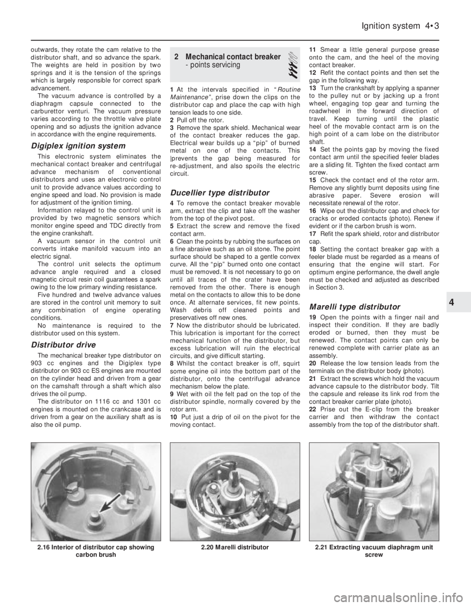
16Wipe out the distributor cap and check for
cracks or eroded contacts (photo). Renew if
evident or if the carbon brush is worn.
17Refit the spark shield, rotor and distributor
cap.
18Setting the contact breaker gap with a
feeler blade must be regarded as a means of
ensuring that the engine will start. For
optimum engine performance, the dwell angle
must be checked and adjusted as described
in Section 3.
Marelli type distributor
19Open the points with a finger nail and
inspect their condition. If they are badly
eroded or burned, then they must be
renewed. The contact points can only be
renewed complete with carrier plate as an
assembly.
20Release the low tension leads from the
terminals on the distributor body (photo).
21Extract the screws which hold the vacuum
advance capsule to the distributor body. Tilt
the capsule and release its link rod from the
contact breaker carrier plate (photo).
22Prise out the E-clip from the breaker
carrier and then withdraw the contact
assembly from the top of the distributor shaft.
Ignition system 4•3
2.21 Extracting vacuum diaphragm unit
screw2.20 Marelli distributor2.16 Interior of distributor cap showing
carbon brush
4
Page 76 of 303
5 Condenser (capacitor)-
removal, testing and refitting
1
The purpose of the condenser (sometimes
known as the capacitor) is to ensure that when
the contact breaker points open there is no
sparking across them which would weaken
the spark and cause rapid deterioration of the
points.
The condenser is fitted in parallel with the
contact breaker points. If it develops a short
circuit it will cause ignition failure as the points
will be prevented from interrupting the low
tension circuit.
1If the engine becomes very difficult to start
(or begins to misfire whilst running) and the
breaker points show signs of excessive
burning, suspect the condenser has failed
with open circuit. A test can be made by
separating the points by hand with the ignition
switched on. If this is accompanied by a
bright spark at the contact points, it is
indicative that the condenser has failed.
2Without special test equipment, the only
sure way to diagnose condenser trouble is to
replace a suspected unit with a new one and
note if there is any improvement.
3To remove the condenser from the
distributor, take out the screw which secures
it to the distributor body and disconnect its
leads from the terminals.
4When fitting the condenser, it is vital to
ensure that the fixing screw is secure. The
lead must be secure on the terminal with no
chance of short circuiting.
6 Distributor-
removal and refitting
3
1Remove the spark plug from No. 4 cylinder
and then turn the crankshaft either by
applying a spanner to the pulley nut or by
jacking up a front wheel, engaging top gear
and turning the wheel in the forward direction
of travel.
2Place a finger over the plug hole and feel
the compression being generated as the
piston rises up the cylinder bore.
3Alternatively, if the rocker cover is off,
check that the valves on No. 1 cylinder are
closed.
4Continue turning the crankshaft until the
flywheel and flywheel housing (BTDC) ignition
timing marks are in alignment. Number 4
piston is now in firing position.
5Remove the distributor cap and place it to
one side complete with high tension leads.
6Disconnect the distributor vacuum hose
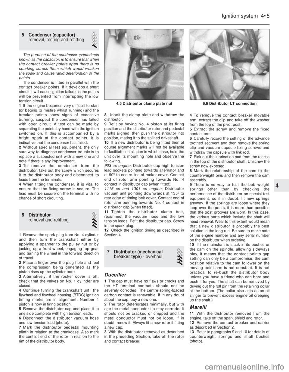
and low tension lead (photo).
7Mark the distributor pedestal mounting
plinth in relation to the crankcase. Also mark
the contact end of the rotor in relation to the
rim of the distributor body.8Unbolt the clamp plate and withdraw the
distributor.
9Refit by having No. 4 piston at its firing
position and the distributor rotor and pedestal
marks aligned, then push the distributor into
position, mating it to the splined driveshaft.
10If a new distributor is being fitted then of
course alignment marks will not be available
to facilitate installation in which case, hold the
unit over its mounting hole and observe the
following.
903 cc engine: Distributor cap high tension
lead sockets pointing towards alternator and
at 90º to centre line of rocker cover. Contact
end of rotor arm pointing towards No. 4
contact in distributor cap (when fitted).
1116 cc and 1301 cc engine: Distributor
vacuum unit pointing downwards at 135º to
rear edge of timing belt cover. Contact end of
rotor arm pointing towards No. 4 contact in
distributor cap (when fitted).
11Tighten the distributor clamp bolt,
reconnect the vacuum hose and the low
tension leads. Refit the distributor cap. Screw
in the spark plug.
12Check the ignition timing as described in
Section 4.
7 Distributor (mechanical
breaker type)- overhaul
3
Ducellier
1The cap must have no flaws or cracks and
the HT terminal contacts should not be
severely corroded. The centre spring-loaded
carbon contact is renewable. If in any doubt
about the cap, buy a new one.
2The rotor deteriorates minimally, but with
age the metal conductor tip may corrode. It
should not be cracked or chipped and the
metal conductor must not be loose. If in
doubt, renew it. Always fit a new rotor if fitting
a new cap.
3With the distributor removed as described
in the preceding Section, take off the rotor
and contact breaker.4To remove the contact breaker movable
arm, extract the clip and take off the washer
from the top of the pivot post.
5Extract the screw and remove the fixed
contact arm.
6Carefully record the setting of the advance
toothed segment and then remove the spring
clip and vacuum capsule fixing screws and
withdraw the capsule with link rod.
7Pick out the lubrication pad from the recess
in the top of the distributor shaft. Unscrew the
screw now exposed.
8Mark the relationship of the cam to the
counterweight pins and then remove the cam
assembly.
9There is no way to test the bob weight
springs other than by checking the
performance of the distributor on special test
equipment, so if in doubt, fit new springs
anyway. If the springs are loose where they
loop over the posts, it is more than possible
that the post grooves are worn. In this case,
the various parts which include the shaft will
need renewal. Wear to this extent would mean
that a new distributor is probably the best
solution in the long run. Be sure to make note
of the engine number and any serial number
on the distributor when ordering.
10If the mainshaft is slack in its bushes or
the cam on the spindle, allowing sideways
play, it means that the contact points gap
setting can only be a compromise; the cam
position relative to the cam follower on the
moving point arm is not constant. It is not
practical to re-bush the distributor body
unless you have a friend who can bore and
bush it for you. The shaft can be removed by
driving out the roll pin from the retaining collar
at the bottom. (The collar also acts as an oil
slinger to prevent excess engine oil creeping
up the shaft.)
Marelli
11With the distributor removed from the
engine, take off the spark shield and rotor.
12Remove the contact breaker and carrier
as described in Section 2.
13Refer to paragraphs 9 and 10 for details of
counterweight springs and shaft bushes
(photo).
Ignition system 4•5
6.6 Distributor LT connection4.5 Distributor clamp plate nut
4
Page 111 of 303
balljoint from the hub carrier using a suitable
“splitter” tool. If such a tool is not available,
support the base of the brake disc and drive
the balljoint taper pin downwards, but screw
on the nut to protect the threads.
4Remove the hub carrier.
5Refitting is a reversal of removal, use a new
driveshaft nut and tighten all nuts and bolts to
the specified torque. Stake the driveshaft nut
after tightening.
6 Track control arm-
removal and refitting
3
1Raise the front of the car and support it
securely.
2Unless a special tool is available to press
the track control arm balljoint from the hub
carrier, the driveshaft will have to be
disconnected as described in Chapter 7,
Section 2, paragraphs 1 to 8 to provide more
space to enable the balljoint taper pin to be
driven from the hub carrier. This should now
be done as described in the preceding
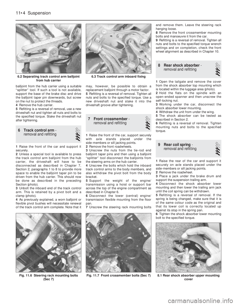
Section (photo).
3Unbolt the inboard end of the track control
arm. This is retained by a pivot bolt and a
clamp (photo).
4As previously explained, a worn balljoint or
flexible pivot bushes will necessitate renewal
of the track control arm complete. Note that itmay, however, be possible to obtain a
replacement balljoint through a motor factor.
5Refitting is a reversal of removal. Tighten all
nuts and bolts to the specified torque. Use a
new driveshaft nut and stake it into the
driveshaft groove after tightening.
7 Front crossmember-
removal and refitting
3
1Raise the front of the car, support securely
with axle stands placed under the
side-members or sill jacking points.
2Remove the front roadwheels.
3Unscrew the nuts from the tie-rod end
balljoint taper pins and then using a balljoint
“splitter” tool disconnect the balljoints from
the steering arms on the hub carrier.
4Unscrew the bolts which hold the inboard
track control arms to the body members, and
also withdraw the pivot bolt from the body
bracket.
5Support the weight of the engine/
transmission using a hoist or support bar
across the top of the engine compartment as
described in Chapter 6.
6Disconnect the lower (central) engine/
transmission flexible mounting from the floor
pan.
7Unscrew the steering rack mounting boltsand remove them. Leave the steering rack
hanging loose.
8Remove the front crossmember mounting
bolts and manoeuvre it from the car.
9Refitting is a reversal of removal. Tighten all
nuts and bolts to the specified torque wrench
settings and on completion, check the front
wheel alignment as described in Chapter 10.
8 Rear shock absorber-
removal and refitting
3
1Open the tailgate and remove the cover
from the shock absorber top mounting which
is located within the luggage area (photo).
2Hold the flats on the spindle with an
open-ended spanner and then unscrew the
self-locking nut.
3Working under the car, disconnect the
shock absorber lower mounting.
4Withdraw the unit from under the wing.
5The shock absorber can be tested as
described in Section 2.
6Refitting is a reversal of removal. Tighten
mounting nuts and bolts to the specified
torque.
9 Rear coil spring-
removal and refitting
3
1Raise the rear of the car and support it
securely on axle stands placed under the
side-members or sill jacking points.
2Remove the roadwheel.
3Place a jack under the brake drum and
support the suspension trailing arm.
4Disconnect the shock absorber lower
mounting and then lower the trailing arm jack
until the coil spring can be withdrawn.
5Refitting is a reversal of removal. If the
spring is being changed, make sure that it is
of the same colour code as the original and
that its lower coil is correctly located up
against its stop in the spring pan.
6Tighten the shock absorber lower mounting
bolt to the specified torque.
11•4 Suspension
8.1 Rear shock absorber upper mounting
coverFig. 11.7 Front crossmember bolts (Sec 7)Fig. 11.6 Steering rack mounting bolts
(Sec 7)
6.3 Track control arm inboard fixing6.2 Separating track control arm balljoint
from hub carrier
Page 112 of 303
10 Trailing arm rubber bush-
renewal
3
1A worn trailing arm rubber bush may be
renewed in the following way.
2Raise the rear of the car and support
securely on axle stands placed under the
body side-members or sill jacking points.
3Remove the roadwheels.
4Unscrew and remove both pivot bolts
which hold the forward ends of the trailing
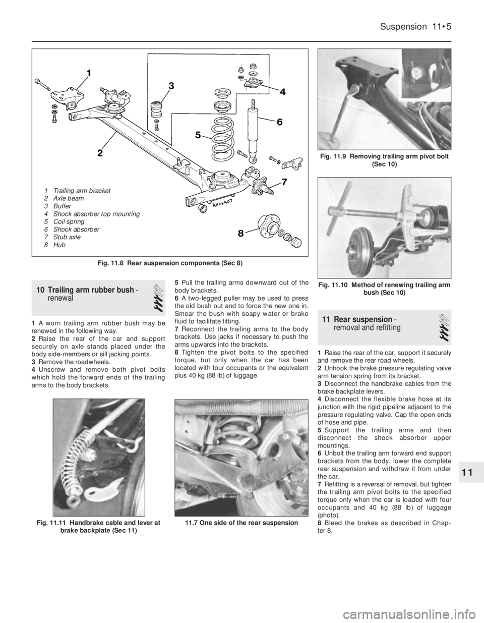
arms to the body brackets.5Pull the trailing arms downward out of the
body brackets.
6A two-legged puller may be used to press
the old bush out and to force the new one in.
Smear the bush with soapy water or brake
fluid to facilitate fitting.
7Reconnect the trailing arms to the body
brackets. Use jacks if necessary to push the
arms upwards into the brackets.
8Tighten the pivot bolts to the specified
torque, but only when the car has been
located with four occupants or the equivalent
plus 40 kg (88 lb) of luggage.11 Rear suspension-
removal and refitting
3
1Raise the rear of the car, support it securely
and remove the rear road wheels.
2Unhook the brake pressure regulating valve
arm tension spring from its bracket.
3Disconnect the handbrake cables from the
brake backplate levers.
4Disconnect the flexible brake hose at its
junction with the rigid pipeline adjacent to the
pressure regulating valve. Cap the open ends
of hose and pipe.
5Support the trailing arms and then
disconnect the shock absorber upper
mountings.
6Unbolt the trailing arm forward end support
brackets from the body, lower the complete
rear suspension and withdraw it from under
the car.
7Refitting is a reversal of removal, but tighten
the trailing arm pivot bolts to the specified
torque only when the car is loaded with four
occupants and 40 kg (88 lb) of luggage
(photo).
8Bleed the brakes as described in Chap-
ter 8.
Suspension 11•5
Fig. 11.9 Removing trailing arm pivot bolt
(Sec 10)
Fig. 11.8 Rear suspension components (Sec 8)
11.7 One side of the rear suspensionFig. 11.11 Handbrake cable and lever at
brake backplate (Sec 11)
Fig. 11.10 Method of renewing trailing arm
bush (Sec 10)
11
1 Trailing arm bracket
2 Axle beam
3 Buffer
4 Shock absorber top mounting
5 Coil spring
6 Shock absorber
7 Stub axle
8 Hub
Page 301 of 303
F
Facia - 12•10, 13•107
Fan -2•3, 13•57, 13•71, 13•84
Fast idle adjustment -3•7, 3•9, 3•10, 3•11,
13•64
Fault finding- REF`•9et seq
Fault finding - braking system -8•9
Fault finding - clutch -5•3
Fault finding - cooling and heating systems
-2•8
Fault finding - driveshafts and hubs -7•6
Fault finding - Econometer -9•12
Fault finding - electrical system -9•14,
REF•9
Fault finding - engine -1•35, 1•36, 2•8,
3•13, 4•9, 13•92, REF•10, REF•11
Fault finding - fuel system -3•9, 3•13,
13•84
Fault finding - ignition system -4•9,
REF•11
Fault finding - Microplex ignition system -
13•92
Fault finding - steering - 10•4
Fault finding - suspension - 11•6
Fault finding - transmission -6•4
Fault finding - turbocharger system - 13•84
Filling - 12•3
Final drive output shafts - 13•94
Fire -0•5
Float adjustment -3•7, 3•8, 3•10, 3•11,
13•64, 13•66
Flywheel -1•19, 1•21, 1•31, 13•46, 13•53
Fog lamps - 13•106
Fuel evaporation control system - 13•78
Fuel filter - 13•67, 13•72, 13•74, 13•79
Fuel gauge fault -9•14
Fuel injection electronic control unit (ECU)
- 13•77
Fuel injection system - 13•68, 13•69
Fuel injection system fault finding - 13•84
Fuel injectors - 13•69, 13•70, 13•71, 13•76,
13•77, 13•81, 13•84
Fuel level transmitter -3•5
Fuel pressure regulator - 13•70
Fuel pump -3•5, 13•61, 13•69, 13•72,
13•76, 13•80, 13•81
Fuel rail - 13•70, 13•81
Fuel system-3•1et seq, 13•60, REF•4
Fuel system fault finding -3•9, 3•13
Fuel tank -3•5, 13•61, 13•72
Fume or gas intoxication -0•5
Fuses -9•5, 13•105
G
Gaiters -7•2, 10•2, 13•98
Gashes in bodywork - 12•2
Gaskets -1•20
Gearbox - SeeTransmission
Gearchange lever -6•2
Gearchange linkage - 13•94, 13•95
Glossary of technical terms- REF•13et seq
Grille - 12•3, 13•113
H
Handbrake -8•8, 8•9, REF•1
Handles - 12•11
HC emissions - REF•4
Headlamp -9•6, 9•7, 13•105, 13•106
Heated tailgate window -9•10
Heater -2•5, 2•6, 13•58, 13•59, 13•108
Heater fault -2•8
Horn -9•6, 13•106
Horn fault -9•14
HT leads - 13•92
Hubs -7•3, 7•4, 11•3
Hydraulic hoses and pipes -8•6
Hydraulic system -8•7
Hydrofluoric acid -0•5
I
Idle speed adjustment -3•7, 13•62, 13•65,
13•68, 13•75, 13•79
Idling fault -1•36, 3•13, 13•84
Ignition coil - 13•86, 13•90, 13•91
Ignition switch -4•8
Ignition system-4•1et seq, 13•85
Ignition system fault finding -4•9, 9•14,
REF•11
Ignition unit - 13•89
Indicators -9•7
Injectors - 13•69, 13•70, 13•71, 13•76,
13•77, 13•81, 13•84
Inlet manifold - 13•70, 13•77, 13•80
Instrument panel -9•8, 13•107
Intercooler - 13•84
Interior lamps -9•5, 9•8
Introduction to the Fiat Uno -0•4
J
Jacking -0•8
Joint mating faces and gaskets - REF•8
Jump starting -0•7
L
Lambda sensor - 13•82
Lamps -9•6, 9•7, 9•8
Leaks -0•9, 1•36, 13•84
LED (light emitter diode) -9•12
Lights fault -9•14
Locknuts,locktabs and washers - REF•8
Locks -9•11, 10•4, 12•4, 12•6, 12•7,
13•109
Loudspeakers -9•11
Lubricants and fluids -0•13
M
Magnetic impulse generator winding -
13•86
Main bearings -1•20, 1•30, 13•52
Maintenance -0•10, 13•18
Manifolds -3•12, 13•70, 13•77, 13•80
Master cylinder -8•5, 13•103, 13•93
Microplex ignition system - 13•86, 13•89Microplex ignition system fault finding -
13•92
Mirrors - 12•11, 13•111, REF•1
Misfire -1•35, 4•9, REF•11
Mixture adjustment -3•7, 13•62, 13•65,
13•68, 13•75, 13•79
MOT test checks- REF•1et seq
Mountings -1•13, 1•27, 13•26, 13•35,
13•49
N
Needle valve - 13•66
Number plate lamp -9•7
O
Oil cooler - 13•36
Oil filter -1•8
Oil level sensor - 13•110, 13•111
Oil pressure fault -1•36, REF•11
Oil pump -1•13, 1•19, 1•22, 1•26, 1•29,
13•24, 13•30, 13•35, 13•46, 13•53
Oil seals -1•20, 13•41, 13•44, 13•45,
13•94, REF•8
Oil,engine -0•6, 0•13, 1•3, 1•4, 1•8
Oil,transmission -0•6, 0•13, 6•1, 13•14,
13•95
Overheating -2•8, 4•9, REF•11
P
Pad wear sensor - 13•110
Pads -8•2, 13•100, 13•101
Parking lamp -9•7
Pedals -5•2, 8•9, 13•92, 13•102
Pinking -1•36, 13•84, REF•11
Pistons -1•12, 1•18, 1•22, 1•26, 1•30,
13•25, 13•26, 13•30, 13•35, 13•47,
13•48, 13•53
Plastic components - 13•111
Points -4•2, 4•3
Poisonous or irritant substances -0•5
Power module - 13•90
Pre-ignition -1•36, 13•84, REF•11
Pressure regulating valve -8•6, 13•102
Pressure sensor - 13•86
R
Radiator -2•3, 12•3, 13•57, 13•113
Radio -9•10, 13•110
Rear lamp cluster -9•7
Regulator (voltage) -9•4
Regulator (window) - 12•7
Relays -9•5, 13•71, 13•105
Repair procedures - REF•8
Respraying - 12•3
Rocker cover - 13•19
Rockers -1•19
Roof rack - 12•11
Routine maintenance -0•10, 13•18
Rust holes in bodywork - 12•2
REF•18Index