trailer FORD B MAX 2013 1.G Owners Manual
[x] Cancel search | Manufacturer: FORD, Model Year: 2013, Model line: B MAX, Model: FORD B MAX 2013 1.GPages: 298, PDF Size: 20.63 MB
Page 5 of 298
Downloaded from www.Manualslib.com manuals search engine Automatic Transmission...........................104
Hill Start Assist..............................................107
Brakes
General Information....................................109
Hints on Driving With Anti-LockBrakes...........................................................109
Parking Brake.................................................109
Stability Control
Principle of Operation...................................111
Using Stability Control..................................111
Parking Aids
Principle of Operation..................................112
Parking Aid.......................................................112
Rear View Camera.........................................114
Cruise Control
Principle of Operation..................................117
Using Cruise Control.....................................117
Driving Aids
Active City Stop..............................................119
Load Carrying
General Information.....................................121
Luggage Anchor Points................................121
Rear Under Floor Storage...........................121
Cargo Nets.......................................................122
Luggage Covers.............................................122
Dog Guard........................................................122
Towing
Towing a Trailer.............................................124
Tow Ball............................................................125
Towing Points.................................................127
Towing the Vehicle on Four Wheels -Vehicles With: ManualTransmission..............................................128
Towing the Vehicle on Four Wheels -Vehicles With: AutomaticTransmission..............................................128
Driving Hints
Breaking-In.....................................................130
Cold Weather Precautions........................130
Driving Through Water...............................130
Floor Mats.......................................................130
Roadside Emergencies
Hazard Warning Flashers...........................132
First Aid Kit......................................................132
Warning Triangle...........................................132
Jump-Starting the Vehicle.........................132
Fuses
Fuse Box Locations......................................134
Fuse Specification Chart - Vehicles BuiltUp To: 04-01-2013...................................135
Fuse Specification Chart - Vehicles BuiltFrom: 05-01-2013....................................144
Changing a Fuse...........................................150
Maintenance
General Information....................................152
Opening and Closing the Hood...............152
Under Hood Overview - 1.0LEcoBoost™.................................................154
Under Hood Overview - 1.4L Duratec-16V(Sigma)/1.6L Duratec-16V Ti-VCT(Sigma)........................................................155
Under Hood Overview - 1.5LDuratorq-TDCi/1.6L Duratorq-TDCi(DV) Diesel.................................................156
Engine Oil Dipstick - 1.0LEcoBoost™.................................................157
Engine Oil Dipstick - 1.4L Duratec-16V(Sigma)/1.6L Duratec-16V Ti-VCT(Sigma)........................................................157
Engine Oil Dipstick - 1.5LDuratorq-TDCi/1.6L Duratorq-TDCi(DV) Diesel..................................................157
3B-MAX (CB2) Vehicles Built From: 25-06-2012, Vehicles Built Up To: 31-12-2013Table of Contents
Page 114 of 298
Downloaded from www.Manualslib.com manuals search engine PRINCIPLE OF OPERATION
WARNINGS
The system does not relieve you ofyour responsibility to drive with duecare and attention.
If your vehicles has a non-Fordapproved trailer tow module thesystem may not correctly detectobjects.
The sensors may not detect objectsin heavy rain or other conditions thatcause disruptive reflections.
The sensors may not detect objectswith surfaces that absorb ultrasonicwaves.
The system does not detect objectsthat are moving away from yourvehicle. They will only be detectedshortly after they start to move towardyour vehicle.
Take particular care when reversingwith a tow ball arm or a rear fittedaccessory. For example, a bicyclecarrier. The rear parking aid will onlyindicate the approximate distance fromthe rear bumper to an object.
If you use a high pressure spray towash your vehicle, only spray thesensors briefly from a distance notless than eight inches (20 centimeters).
Note:If your vehicle has a tow ball arm, thesystem is turned off automatically whentrailer lamps (or lighting boards) areconnected to the 13-pin socket through aFord approved trailer tow module.
Note:Keep the sensors free from dirt, iceor snow. Do not clean with sharp objects.
Note:The system may emit false alerts ifit detects a signal using the same frequencyas the sensors or if your vehicle is fullyloaded.
Note:The outer sensors may detect theside walls of a garage. If the distancebetween the outer sensors and the side wallremains constant for three seconds, thealert will turn off. As you continue the innersensors will detect objects directly behindyour vehicle.
PARKING AID
WARNINGS
Sensing is only an aid to detect someobjects when moving forward orbackward at low speeds. Trafficcontrol systems, inclement weather or anexternal motor and fan can affect thesensors; this may include reducedperformance or false activation. To helpavoid personal injury you must read andunderstand the limitations of the systemdetailed in this section.
The parking aid system may notprevent contact with small or movingobjects that are close to the ground.The parking aid system gives an audiblewarning when it detects a large objecthelping to avoid damage to your vehicle.To help avoid personal injury you must takecare when using the parking aid system.
Note:Some add-on equipment can causereduced performance or false activation.For example, large trailer hitches, bike orsurfboard racks.
Note:The parking aid system sensors mustbe kept clean and free from snow or ice toavoid reduced performance or falseactivation. Do not clean the sensors withsharp objects.
Note:If the parking aid sensors aremisaligned due to vehicle bumper damageit will cause reduced performance or falseactivation.
112B-MAX (CB2) Vehicles Built From: 25-06-2012, Vehicles Built Up To: 31-12-2013Parking Aids
Page 118 of 298
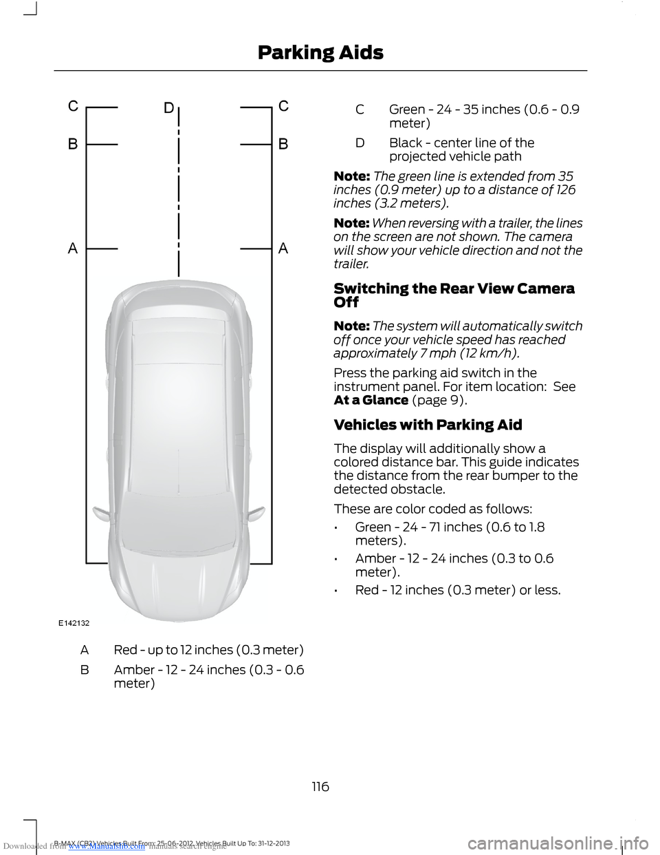
Downloaded from www.Manualslib.com manuals search engine Red - up to 12 inches (0.3 meter)A
Amber - 12 - 24 inches (0.3 - 0.6meter)B
Green - 24 - 35 inches (0.6 - 0.9meter)C
Black - center line of theprojected vehicle pathD
Note:The green line is extended from 35inches (0.9 meter) up to a distance of 126inches (3.2 meters).
Note:When reversing with a trailer, the lineson the screen are not shown. The camerawill show your vehicle direction and not thetrailer.
Switching the Rear View CameraOff
Note:The system will automatically switchoff once your vehicle speed has reachedapproximately 7 mph (12 km/h).
Press the parking aid switch in theinstrument panel. For item location: SeeAt a Glance (page 9).
Vehicles with Parking Aid
The display will additionally show acolored distance bar. This guide indicatesthe distance from the rear bumper to thedetected obstacle.
These are color coded as follows:
•Green - 24 - 71 inches (0.6 to 1.8meters).
•Amber - 12 - 24 inches (0.3 to 0.6meter).
•Red - 12 inches (0.3 meter) or less.
116B-MAX (CB2) Vehicles Built From: 25-06-2012, Vehicles Built Up To: 31-12-2013Parking Aids
Page 126 of 298
Downloaded from www.Manualslib.com manuals search engine TOWING A TRAILER
WARNINGS
Do not exceed 62 mph (100 km/h).This could result in the loss of vehiclecontrol, serious personal injury ordeath.
The rear tire pressures must beincreased by 3 psi (0.2 bar) abovespecification. Do not exceed themaximum pressure stated on the tiresidewall. This could cause serious personalinjury. See Wheels and Tires (page 174).
Do not exceed the maximum grosstrain weight stated on your vehicleidentification plate. This could resultin the loss of vehicle control, seriouspersonal injury or death. See VehicleIdentification Plate (page 186).
Do not exceed the maximumpermissible trailer nose weight(vertical weight on the tow ball) asstated in the vehicle specification chart.This could result in the loss of vehiclecontrol, serious personal injury or death.See Capacities and Specifications(page 186).
The anti-lock braking system doesnot control the overrun brake on thetrailer. This could result in the loss ofvehicle control, serious personal injury ordeath.
When towing a trailer:
•Obey country specific regulations fortowing a trailer.
•Do not exceed 62 mph (100 km/h)even if a country allows higher speedsunder certain conditions.
•Place loads as low as possible andcentral to the axle of your trailer. If youare towing with an unladen vehicle, theload in your trailer should be placedtoward the nose, within the maximumnose load, as this gives the beststability. See Capacities andSpecifications (page 186).
•The trailer nose weight (vertical weighton the tow ball), is essential for thedriving stability of your vehicle andtrailer.
•The vertical weight on the tow ballshould be at least 4% of the trailerweight and not exceed the maximumpermissable weight. See Capacitiesand Specifications (page 186).
•Reduce speed immediately if the trailershows any sign of swaying.
•Use a low gear when descending asteep downhill gradient.
Note:The maximum permissible trailernose weight on the trailer identificationplate is the trailer manufacturer’s testingvalue. The vehicle maximum permissibletrailer nose weight may be lower.
The stability of your vehicle to trailercombination is very much dependent onthe quality of the trailer.
Towing a trailer changes the vehiclehandling characteristics and increasesstopping distances. Adapt your speed anddriving behavior to the load of the trailer.
The gross train weight stated on thevehicle identification plate applies for roadgradients up to 12% and altitudes up to3281 feet (1000 meters) when towing atrailer. In mountainous regions the engineperformance decreases due to lower airdensity with increasing altitude. In highaltitude regions above 3281feet (1000metres), the stipulated maximumpermitted gross train weight must bereduced by 10% for every extra 3281 feet(1000 metres).
124B-MAX (CB2) Vehicles Built From: 25-06-2012, Vehicles Built Up To: 31-12-2013Towing
Page 127 of 298
Downloaded from www.Manualslib.com manuals search engine Note:Not all vehicles are suitable orapproved to have tow bars fitted. See anauthorized dealer for further information.
Trailer Lighting
The electrical system on your vehicle is notsuitable for towing trailers with LED lamps.
TOW BALL
WARNINGS
When not in use, always transportthe tow ball arm securely fastenedin the luggage compartment.
Take special care when fitting thetow ball arm as the safety of yourvehicle and the trailer depends onthis.
Do not use any tools for mounting ordismounting the tow ball arm.
Do not modify the trailer coupling.
Do not disassemble or repair the towball arm.
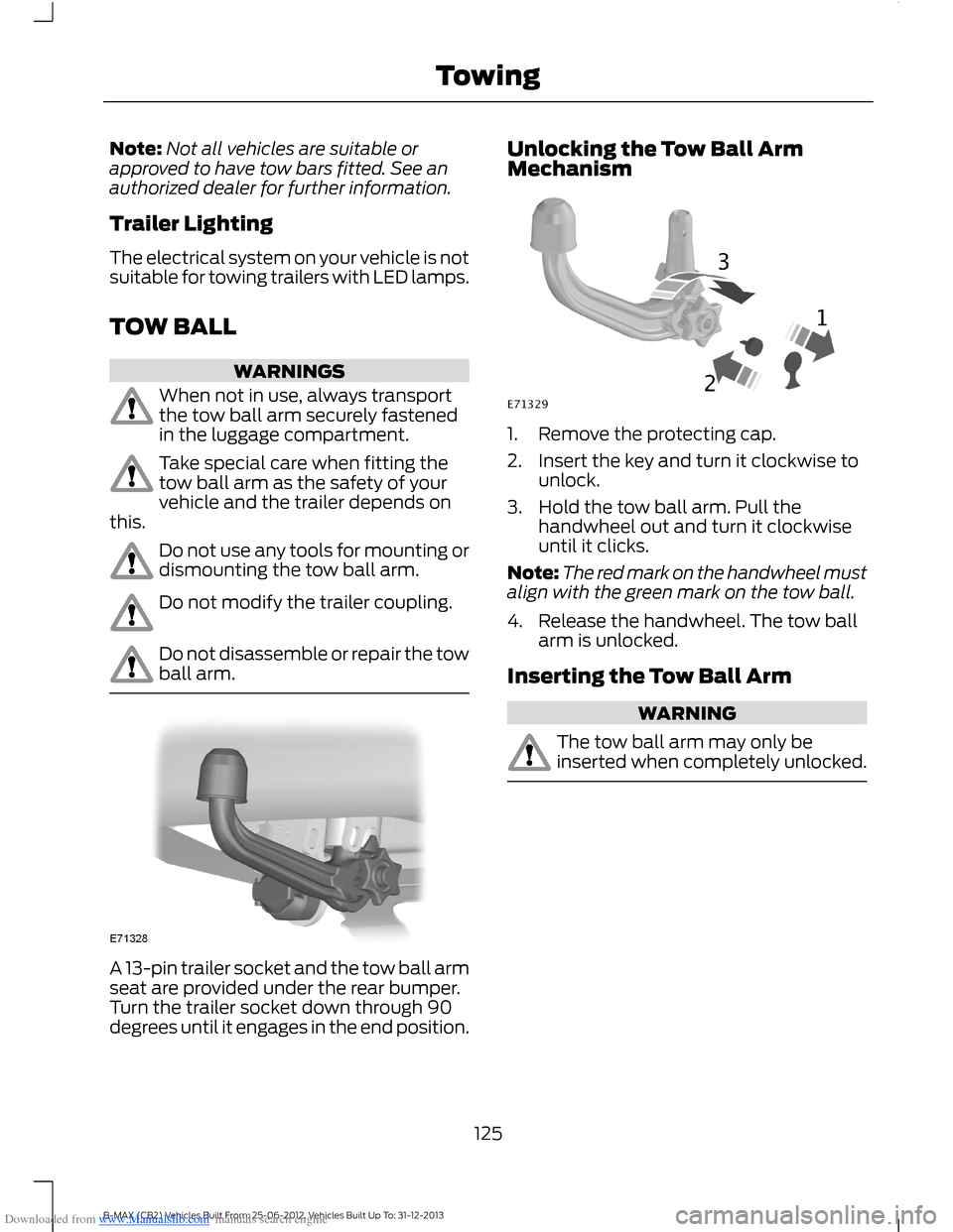
A 13-pin trailer socket and the tow ball armseat are provided under the rear bumper.Turn the trailer socket down through 90degrees until it engages in the end position.
Unlocking the Tow Ball ArmMechanism
1.Remove the protecting cap.
2.Insert the key and turn it clockwise tounlock.
3.Hold the tow ball arm. Pull thehandwheel out and turn it clockwiseuntil it clicks.
Note:The red mark on the handwheel mustalign with the green mark on the tow ball.
4.Release the handwheel. The tow ballarm is unlocked.
Inserting the Tow Ball Arm
WARNING
The tow ball arm may only beinserted when completely unlocked.
125B-MAX (CB2) Vehicles Built From: 25-06-2012, Vehicles Built Up To: 31-12-2013Towing
Page 128 of 298
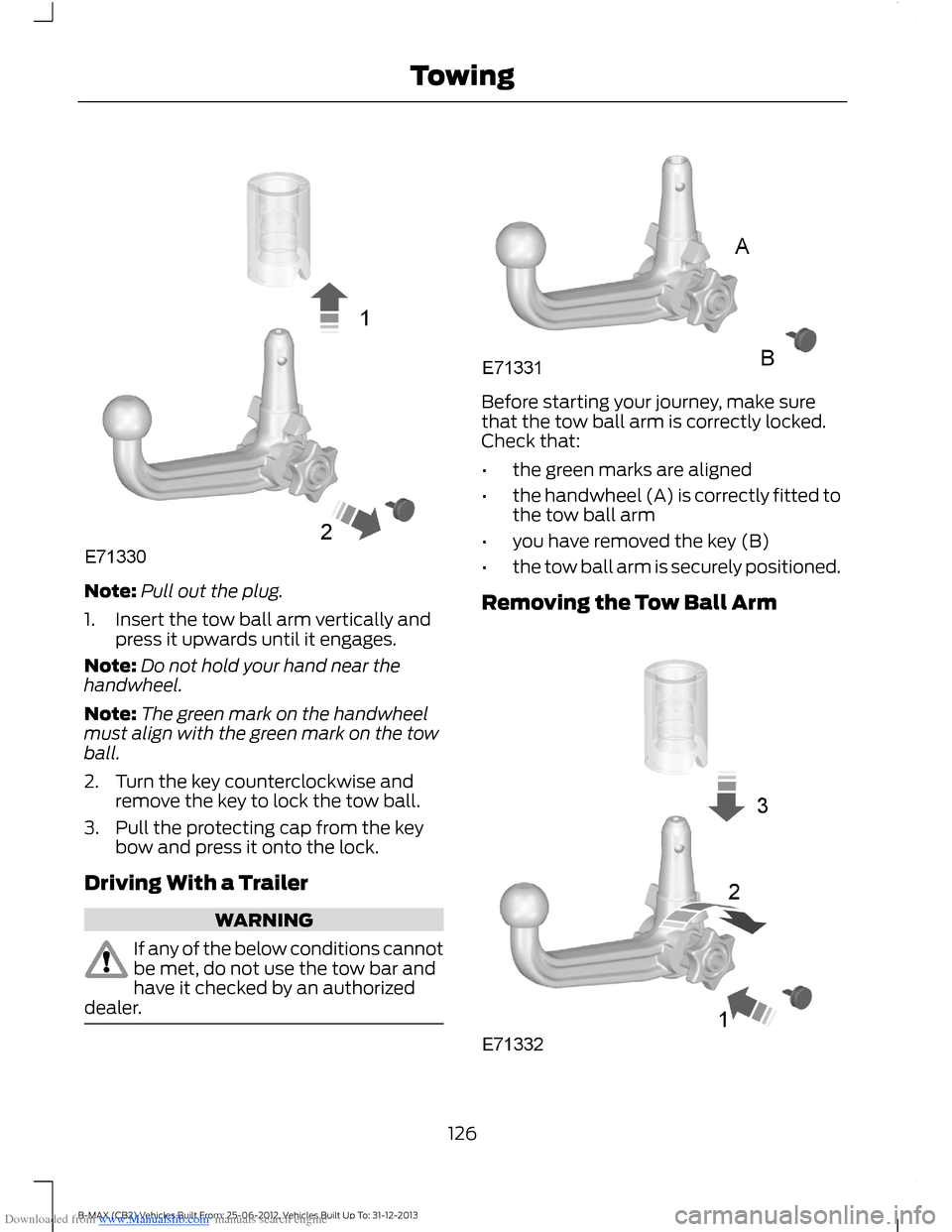
Downloaded from www.Manualslib.com manuals search engine Note:Pull out the plug.
1.Insert the tow ball arm vertically andpress it upwards until it engages.
Note:Do not hold your hand near thehandwheel.
Note:The green mark on the handwheelmust align with the green mark on the towball.
2.Turn the key counterclockwise andremove the key to lock the tow ball.
3.Pull the protecting cap from the keybow and press it onto the lock.
Driving With a Trailer
WARNING
If any of the below conditions cannotbe met, do not use the tow bar andhave it checked by an authorizeddealer.
Before starting your journey, make surethat the tow ball arm is correctly locked.Check that:
•the green marks are aligned
•the handwheel (A) is correctly fitted tothe tow ball arm
•you have removed the key (B)
•the tow ball arm is securely positioned.
Removing the Tow Ball Arm
126B-MAX (CB2) Vehicles Built From: 25-06-2012, Vehicles Built Up To: 31-12-2013Towing
Page 129 of 298
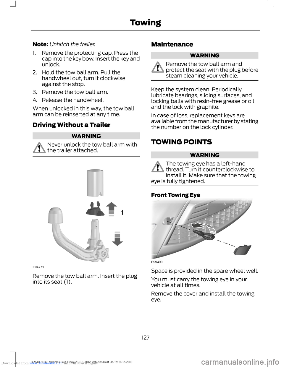
Downloaded from www.Manualslib.com manuals search engine Note:Unhitch the trailer.
1.Remove the protecting cap. Press thecap into the key bow. Insert the key andunlock.
2.Hold the tow ball arm. Pull thehandwheel out, turn it clockwiseagainst the stop.
3.Remove the tow ball arm.
4.Release the handwheel.
When unlocked in this way, the tow ballarm can be reinserted at any time.
Driving Without a Trailer
WARNING
Never unlock the tow ball arm withthe trailer attached.
Remove the tow ball arm. Insert the pluginto its seat (1).
Maintenance
WARNING
Remove the tow ball arm andprotect the seat with the plug beforesteam cleaning your vehicle.
Keep the system clean. Periodicallylubricate bearings, sliding surfaces, andlocking balls with resin-free grease or oiland the lock with graphite.
In case of loss, replacement keys areavailable from the manufacturer by statingthe number on the lock cylinder.
TOWING POINTS
WARNING
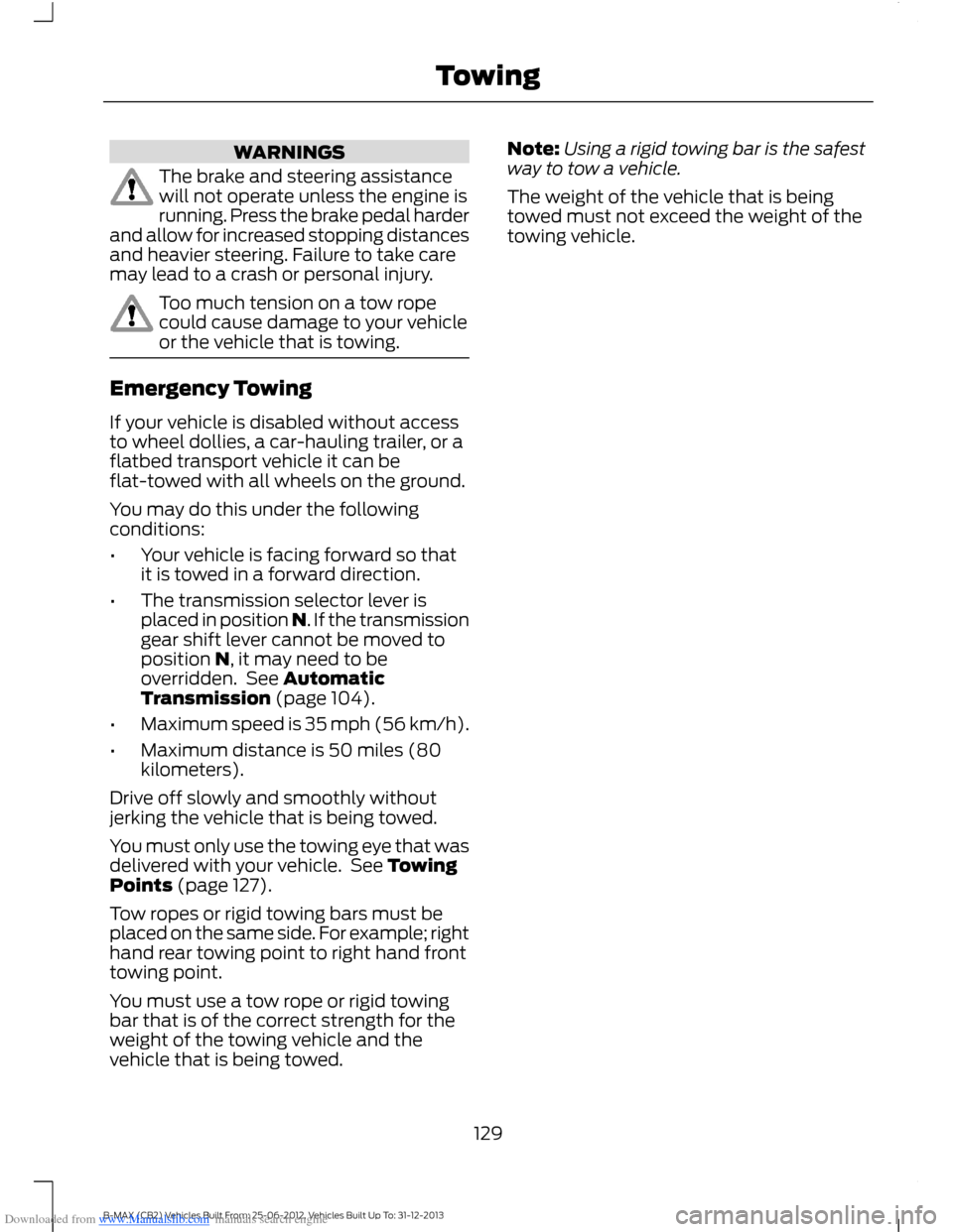
The towing eye has a left-handthread. Turn it counterclockwise toinstall it. Make sure that the towingeye is fully tightened.
Front Towing Eye
Space is provided in the spare wheel well.
You must carry the towing eye in yourvehicle at all times.
Remove the cover and install the towingeye.
127B-MAX (CB2) Vehicles Built From: 25-06-2012, Vehicles Built Up To: 31-12-2013Towing
Page 131 of 298
Downloaded from www.Manualslib.com manuals search engine WARNINGS
The brake and steering assistancewill not operate unless the engine isrunning. Press the brake pedal harderand allow for increased stopping distancesand heavier steering. Failure to take caremay lead to a crash or personal injury.
Too much tension on a tow ropecould cause damage to your vehicleor the vehicle that is towing.
Emergency Towing
If your vehicle is disabled without accessto wheel dollies, a car-hauling trailer, or aflatbed transport vehicle it can beflat-towed with all wheels on the ground.
You may do this under the followingconditions:
•Your vehicle is facing forward so thatit is towed in a forward direction.
•The transmission selector lever isplaced in position N. If the transmissiongear shift lever cannot be moved toposition N, it may need to beoverridden. See AutomaticTransmission (page 104).
•Maximum speed is 35 mph (56 km/h).
•Maximum distance is 50 miles (80kilometers).
Drive off slowly and smoothly withoutjerking the vehicle that is being towed.
You must only use the towing eye that wasdelivered with your vehicle. See TowingPoints (page 127).
Tow ropes or rigid towing bars must beplaced on the same side. For example; righthand rear towing point to right hand fronttowing point.
You must use a tow rope or rigid towingbar that is of the correct strength for theweight of the towing vehicle and thevehicle that is being towed.
Note:Using a rigid towing bar is the safestway to tow a vehicle.
The weight of the vehicle that is beingtowed must not exceed the weight of thetowing vehicle.
129B-MAX (CB2) Vehicles Built From: 25-06-2012, Vehicles Built Up To: 31-12-2013Towing
Page 141 of 298
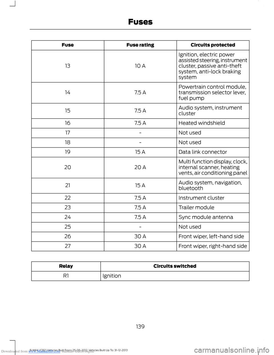
Downloaded from www.Manualslib.com manuals search engine Circuits protectedFuse ratingFuse
Ignition, electric powerassisted steering, instrumentcluster, passive anti-theftsystem, anti-lock brakingsystem
10 A13
Powertrain control module,transmission selector lever,fuel pump7.5 A14
Audio system, instrumentcluster7.5 A15
Heated windshield7.5 A16
Not used-17
Not used-18
Data link connector15 A19
Multi function display, clock,internal scanner, heatingvents, air conditioning panel20 A20
Audio system, navigation,bluetooth15 A21
Instrument cluster7.5 A22
Trailer module7.5 A23
Sync module antenna7.5 A24
Not used-25
Front wiper, left-hand side30 A26
Front wiper, right-hand side30 A27
Circuits switchedRelay
IgnitionR1
139B-MAX (CB2) Vehicles Built From: 25-06-2012, Vehicles Built Up To: 31-12-2013Fuses
Page 143 of 298
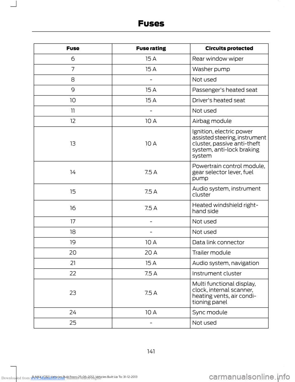
Downloaded from www.Manualslib.com manuals search engine Circuits protectedFuse ratingFuse
Rear window wiper15 A6
Washer pump15 A7
Not used-8
Passenger's heated seat15 A9
Driver's heated seat15 A10
Not used-11
Airbag module10 A12
Ignition, electric powerassisted steering, instrumentcluster, passive anti-theftsystem, anti-lock brakingsystem
10 A13
Powertrain control module,gear selector lever, fuelpump7.5 A14
Audio system, instrumentcluster7.5 A15
Heated windshield right-hand side7.5 A16
Not used-17
Not used-18
Data link connector10 A19
Trailer module20 A20
Audio system, navigation15 A21
Instrument cluster7.5 A22
Multi functional display,clock, internal scanner,heating vents, air condi-tioning panel
7.5 A23
Sync module10 A24
Not used-25
141B-MAX (CB2) Vehicles Built From: 25-06-2012, Vehicles Built Up To: 31-12-2013Fuses