check engine light FORD C MAX 2011 2.G Owners Manual
[x] Cancel search | Manufacturer: FORD, Model Year: 2011, Model line: C MAX, Model: FORD C MAX 2011 2.GPages: 296, PDF Size: 7.87 MB
Page 3 of 296
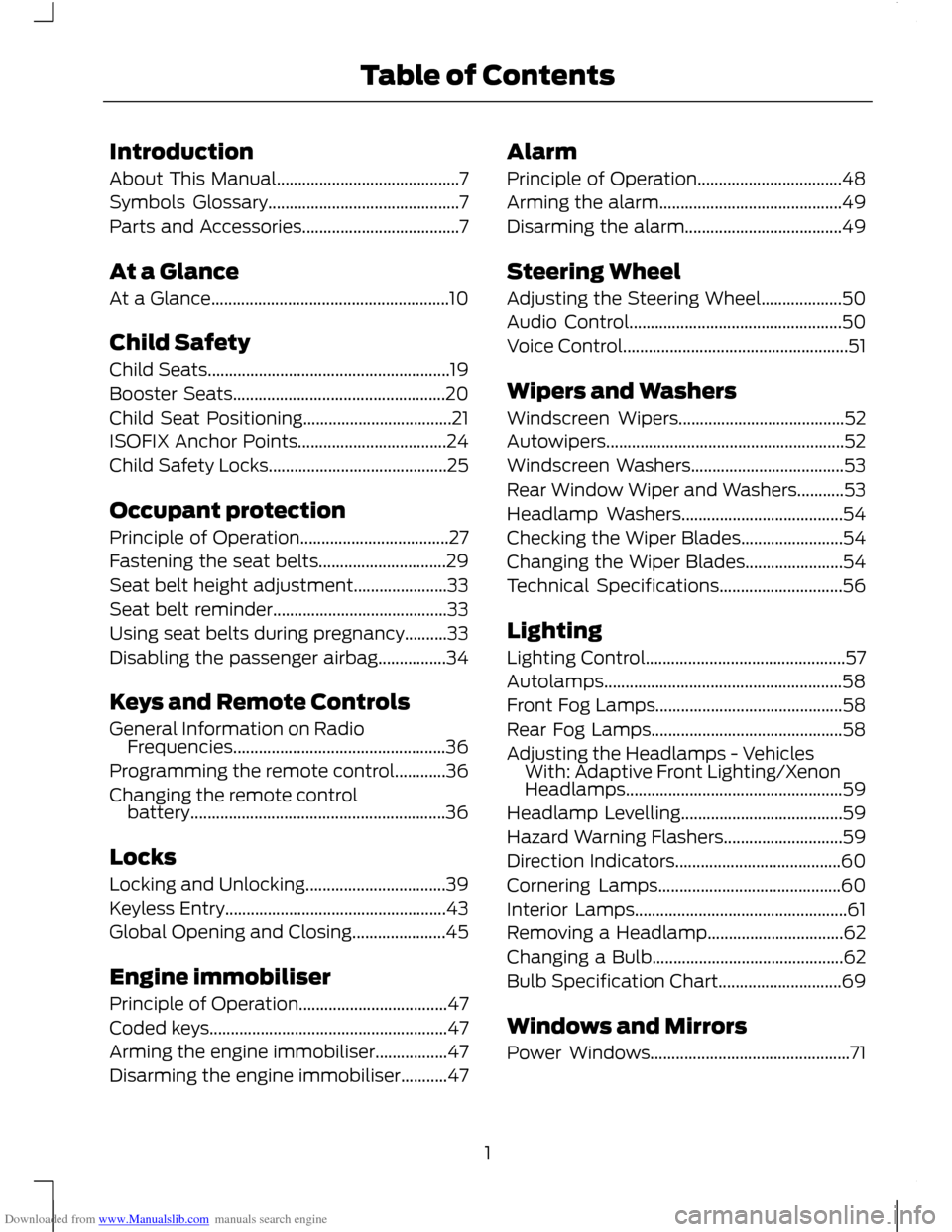
Downloaded from www.Manualslib.com manuals search engine Introduction
About This Manual...........................................7
Symbols Glossary.............................................7
Parts and Accessories.....................................7
At a Glance
At a Glance........................................................10
Child Safety
Child Seats.........................................................19
Booster Seats..................................................20
Child Seat Positioning...................................21
ISOFIX Anchor Points...................................24
Child Safety Locks..........................................25
Occupant protection
Principle of Operation...................................27
Fastening the seat belts..............................29
Seat belt height adjustment......................33
Seat belt reminder.........................................33
Using seat belts during pregnancy..........33
Disabling the passenger airbag................34
Keys and Remote Controls
General Information on Radio
Frequencies..................................................36
Programming the remote control............36
Changing the remote control battery............................................................36
Locks
Locking and Unlocking.................................39
Keyless Entry....................................................43
Global Opening and Closing......................45
Engine immobiliser
Principle of Operation...................................47
Coded keys........................................................47
Arming the engine immobiliser.................47
Disarming the engine immobiliser...........47 Alarm
Principle of Operation..................................48
Arming the alarm...........................................49
Disarming the alarm.....................................49
Steering Wheel
Adjusting the Steering Wheel...................50
Audio Control..................................................50
Voice Control.....................................................51
Wipers and Washers
Windscreen Wipers.......................................52
Autowipers........................................................52
Windscreen Washers....................................53
Rear Window Wiper and Washers...........53
Headlamp Washers......................................54
Checking the Wiper Blades........................54
Changing the Wiper Blades.......................54
Technical Specifications.............................56
Lighting
Lighting Control...............................................57
Autolamps........................................................58
Front Fog Lamps............................................58
Rear Fog Lamps.............................................58
Adjusting the Headlamps - Vehicles
With: Adaptive Front Lighting/Xenon
Headlamps...................................................59
Headlamp Levelling......................................59
Hazard Warning Flashers............................59
Direction Indicators.......................................60
Cornering Lamps...........................................60
Interior Lamps..................................................61
Removing a Headlamp................................62
Changing a Bulb.............................................62
Bulb Specification Chart.............................69
Windows and Mirrors
Power Windows...............................................71
1
Table of Contents
Page 83 of 296
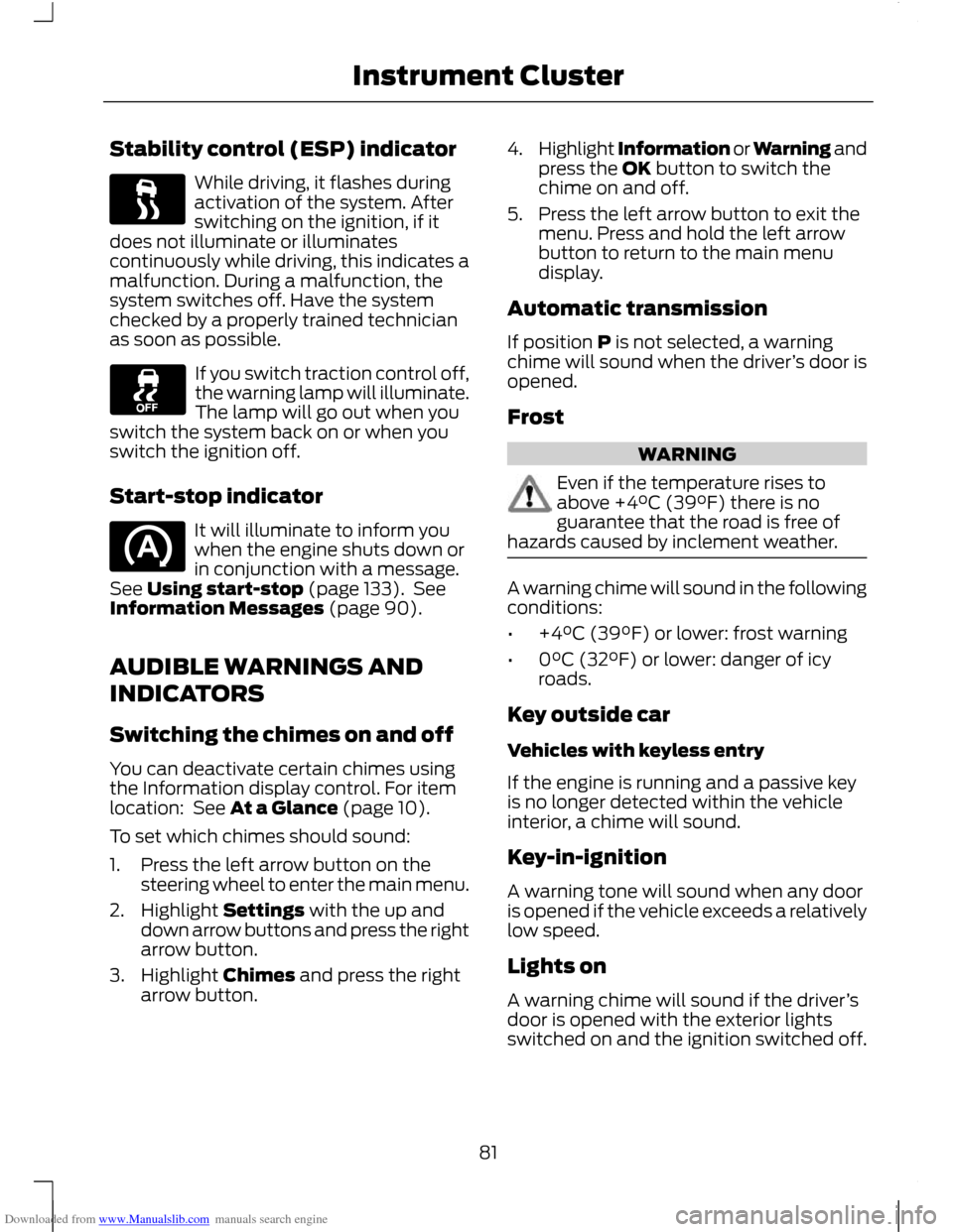
Downloaded from www.Manualslib.com manuals search engine Stability control (ESP) indicator
While driving, it flashes during
activation of the system. After
switching on the ignition, if it
does not illuminate or illuminates
continuously while driving, this indicates a
malfunction. During a malfunction, the
system switches off. Have the system
checked by a properly trained technician
as soon as possible. If you switch traction control off,
the warning lamp will illuminate.
The lamp will go out when you
switch the system back on or when you
switch the ignition off.
Start-stop indicator It will illuminate to inform you
when the engine shuts down or
in conjunction with a message.
See Using start-stop (page 133). See
Information Messages (page 90).
AUDIBLE WARNINGS AND
INDICATORS
Switching the chimes on and off
You can deactivate certain chimes using
the Information display control. For item
location: See At a Glance (page 10).
To set which chimes should sound:
1. Press the left arrow button on the steering wheel to enter the main menu.
2. Highlight Settings with the up and down arrow buttons and press the right
arrow button.
3. Highlight Chimes and press the right arrow button. 4.
Highlight Information or Warning and
press the OK button to switch the
chime on and off.
5. Press the left arrow button to exit the menu. Press and hold the left arrow
button to return to the main menu
display.
Automatic transmission
If position P is not selected, a warning
chime will sound when the driver ’s door is
opened.
Frost WARNING
Even if the temperature rises to
above +4°C (39°F) there is no
guarantee that the road is free of
hazards caused by inclement weather. A warning chime will sound in the following
conditions:
•
+4°C (39°F) or lower: frost warning
• 0°C (32°F) or lower: danger of icy
roads.
Key outside car
Vehicles with keyless entry
If the engine is running and a passive key
is no longer detected within the vehicle
interior, a chime will sound.
Key-in-ignition
A warning tone will sound when any door
is opened if the vehicle exceeds a relatively
low speed.
Lights on
A warning chime will sound if the driver ’s
door is opened with the exterior lights
switched on and the ignition switched off.
81
Instrument Cluster
Page 96 of 296
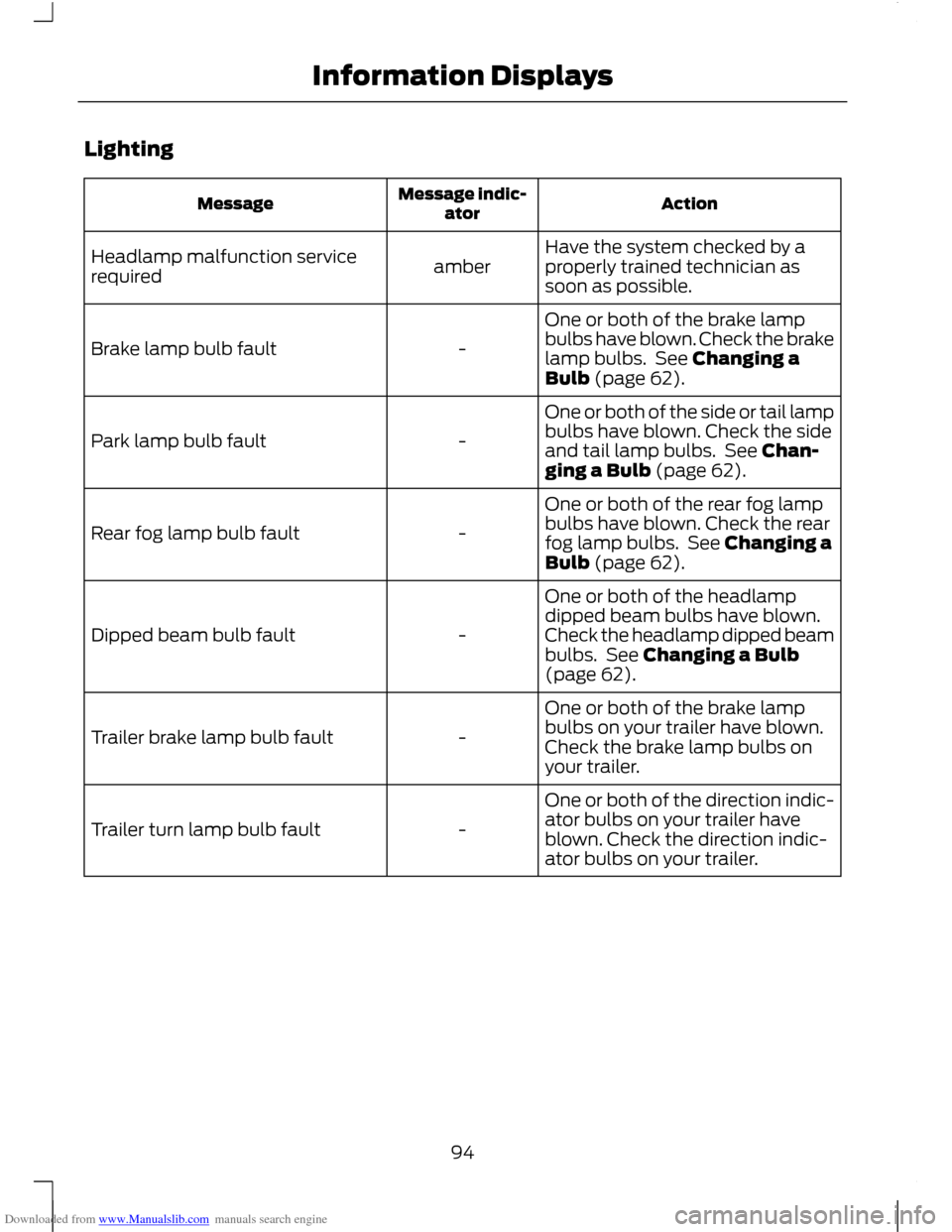
Downloaded from www.Manualslib.com manuals search engine Lighting
Action
Message indic-
ator
Message
Have the system checked by a
properly trained technician as
soon as possible.
amber
Headlamp malfunction service
required
One or both of the brake lamp
bulbs have blown. Check the brake
lamp bulbs. See Changing a
Bulb (page 62).
-
Brake lamp bulb fault
One or both of the side or tail lamp
bulbs have blown. Check the side
and tail lamp bulbs. See Chan-
ging a Bulb (page 62).
-
Park lamp bulb fault
One or both of the rear fog lamp
bulbs have blown. Check the rear
fog lamp bulbs. See Changing a
Bulb (page 62).
-
Rear fog lamp bulb fault
One or both of the headlamp
dipped beam bulbs have blown.
Check the headlamp dipped beam
bulbs. See Changing a Bulb
(page 62).
-
Dipped beam bulb fault
One or both of the brake lamp
bulbs on your trailer have blown.
Check the brake lamp bulbs on
your trailer.
-
Trailer brake lamp bulb fault
One or both of the direction indic-
ator bulbs on your trailer have
blown. Check the direction indic-
ator bulbs on your trailer.
-
Trailer turn lamp bulb fault
94
Information Displays
Page 109 of 296
Downloaded from www.Manualslib.com manuals search engine •
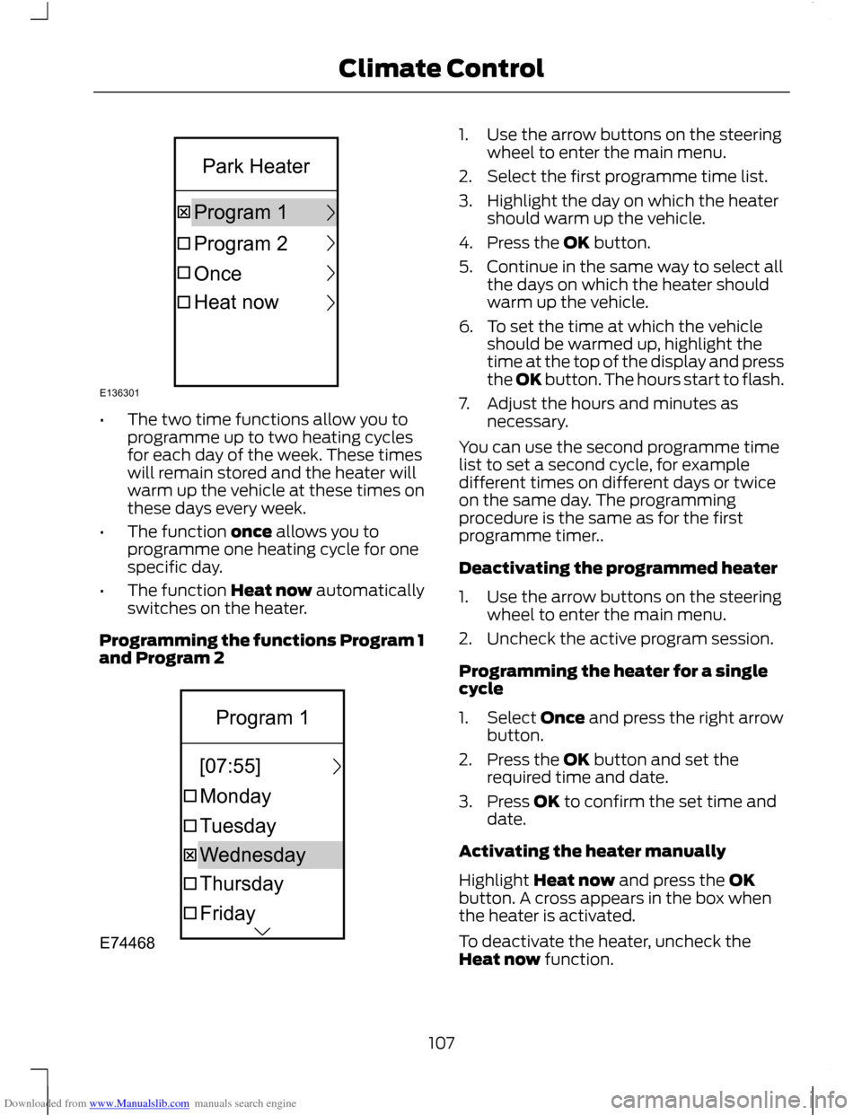
The two time functions allow you to
programme up to two heating cycles
for each day of the week. These times
will remain stored and the heater will
warm up the vehicle at these times on
these days every week.
• The function once allows you to
programme one heating cycle for one
specific day.
• The function Heat now automatically
switches on the heater.
Programming the functions Program 1
and Program 2 1. Use the arrow buttons on the steering
wheel to enter the main menu.
2. Select the first programme time list.
3. Highlight the day on which the heater should warm up the vehicle.
4. Press the OK button.
5. Continue in the same way to select all the days on which the heater should
warm up the vehicle.
6. To set the time at which the vehicle should be warmed up, highlight the
time at the top of the display and press
the OK button. The hours start to flash.
7. Adjust the hours and minutes as necessary.
You can use the second programme time
list to set a second cycle, for example
different times on different days or twice
on the same day. The programming
procedure is the same as for the first
programme timer..
Deactivating the programmed heater
1. Use the arrow buttons on the steering wheel to enter the main menu.
2. Uncheck the active program session.
Programming the heater for a single
cycle
1. Select Once and press the right arrow button.
2. Press the OK button and set the required time and date.
3. Press OK to confirm the set time and date.
Activating the heater manually
Highlight Heat now and press the OK
button. A cross appears in the box when
the heater is activated.
To deactivate the heater, uncheck the
Heat now function.
107
Climate ControlE136301OnceProgram1Program2HeatnowParkHeater E74468FridayThursdayTuesdayMondayWednesday[07:55]Program1
Page 125 of 296
Downloaded from www.Manualslib.com manuals search engine Note:
You can use the socket to power 12
volt appliances that have a maximum
current rating of 15 Amperes. Use only Ford
accessory connectors or connectors
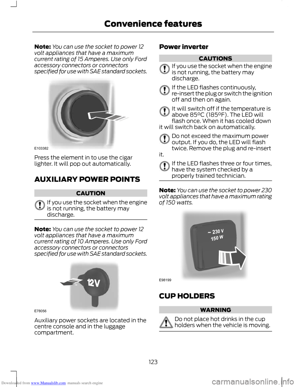
specified for use with SAE standard sockets. Press the element in to use the cigar
lighter. It will pop out automatically.
AUXILIARY POWER POINTS
CAUTION
If you use the socket when the engine
is not running, the battery may
discharge.
Note:
You can use the socket to power 12
volt appliances that have a maximum
current rating of 10 Amperes. Use only Ford
accessory connectors or connectors
specified for use with SAE standard sockets. Auxiliary power sockets are located in the
centre console and in the luggage
compartment. Power inverter CAUTIONS
If you use the socket when the engine
is not running, the battery may
discharge.
If the LED flashes continuously,
re-insert the plug or switch the ignition
off and then on again.
It will switch off if the temperature is
above 85°C (185°F). The LED will
flash once. When it has cooled down
it will switch back on automatically. Do not exceed the maximum power
output. If you do, the LED will flash
twice. Remove the plug and re-insert
it. If the LED flashes three or four times,
have the system checked by a
properly trained technician.
Note:
You can use the socket to power 230
volt appliances that have a maximum rating
of 150 watts. CUP HOLDERS
WARNING
Do not place hot drinks in the cup
holders when the vehicle is moving.
123
Convenience featuresE103382 E78056 E98199
Page 135 of 296
Downloaded from www.Manualslib.com manuals search engine PRINCIPLE OF OPERATION
CAUTION
For vehicles with Start-stop the
battery requirement is different. It
must be replaced by one of exactly
the same specification as the original. The system reduces fuel consumption and
CO2 emissions by shutting down the
engine when the vehicle is idling, for
example at traffic lights. The engine will
automatically restart when the driver
presses the clutch pedal or when required
by a vehicle system, for example to
recharge the battery.
To obtain maximum benefit from the
system, move the gear lever to the neutral
position and release the clutch pedal
during any stop of longer than three
seconds.
USING START-STOP
WARNINGS
The engine may restart
automatically if required by the
system. See Principle of Operation
(page 133). Switch the ignition off before
opening the bonnet or carrying out
any maintenance.
Always switch the ignition off before
leaving your vehicle, as the system
may have shut down the engine but
the ignition will still be live. Note:
The system only operates when the
engine is warm and the outside temperature
is between 0°C (32°F) and 30°C (86°F). Note:
If you stall the engine, and then
depress the clutch pedal within a couple of
seconds, the system will automatically
restart the engine.
Note: The Start-stop indicator will
illuminate green when the engine shuts
down. See Warning Lamps and Indicators
(page 79).
Note: The Start-stop indicator will flash
amber, requiring you to select neutral or
depress the clutch pedal. In conjunction a
message will be shown in the display.
Note: If the system detects a malfunction,
it is deactivated. Have the system checked
by a properly trained technician.
Note: If you have switched the system off,
the switch will be illuminated.
Note: The system is on by default. To
switch the system off, press the switch in
the instrument panel. The system will only
be de-activated for the current ignition
cycle. To turn it on, press the switch again.
For item location. See At a Glance (page
10). To stop the engine
1. Stop the vehicle.
2. Move the gear lever to the neutral
position.
3. Release the clutch pedal.
4. Release the accelerator pedal.
The system may not shut down the engine
under certain conditions, for example:
• To maintain the interior climate.
• Low battery voltage.
• The outside temperature is too low or
too high.
• The driver's door has been opened.
133
Start-Stop
Page 140 of 296
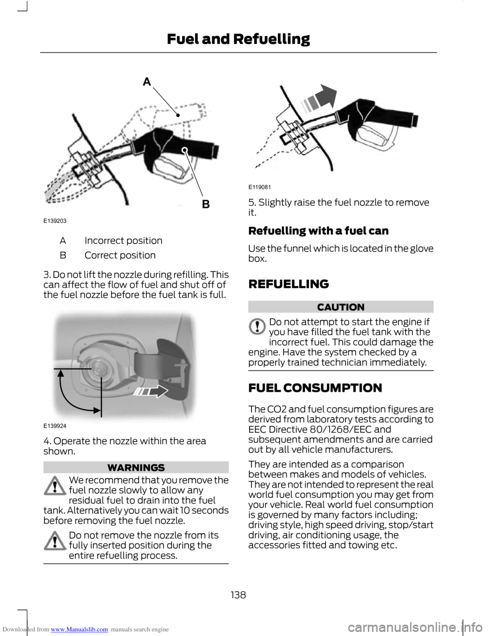
Downloaded from www.Manualslib.com manuals search engine Incorrect position
A
Correct position
B
3. Do not lift the nozzle during refilling. This
can affect the flow of fuel and shut off of
the fuel nozzle before the fuel tank is full. 4. Operate the nozzle within the area
shown.
WARNINGS
We recommend that you remove the
fuel nozzle slowly to allow any
residual fuel to drain into the fuel
tank. Alternatively you can wait 10 seconds
before removing the fuel nozzle. Do not remove the nozzle from its
fully inserted position during the
entire refuelling process. 5. Slightly raise the fuel nozzle to remove
it.
Refuelling with a fuel can
Use the funnel which is located in the glove
box.
REFUELLING
CAUTION
Do not attempt to start the engine if
you have filled the fuel tank with the
incorrect fuel. This could damage the
engine. Have the system checked by a
properly trained technician immediately. FUEL CONSUMPTION
The CO2 and fuel consumption figures are
derived from laboratory tests according to
EEC Directive 80/1268/EEC and
subsequent amendments and are carried
out by all vehicle manufacturers.
They are intended as a comparison
between makes and models of vehicles.
They are not intended to represent the real
world fuel consumption you may get from
your vehicle. Real world fuel consumption
is governed by many factors including;
driving style, high speed driving, stop/start
driving, air conditioning usage, the
accessories fitted and towing etc.
138
Fuel and RefuellingE139203AB E139924 E119081
Page 151 of 296
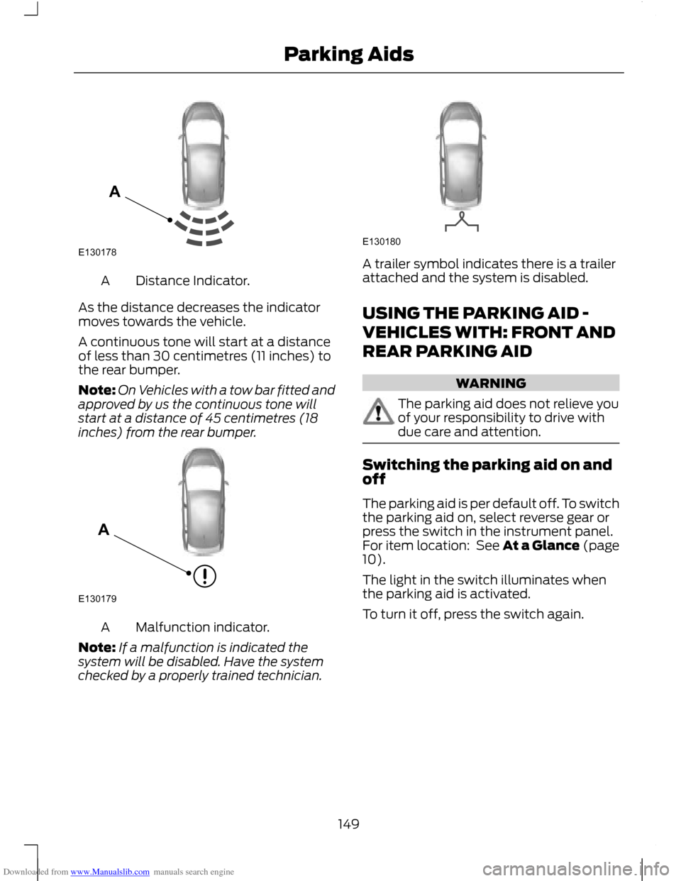
Downloaded from www.Manualslib.com manuals search engine Distance Indicator.
A
As the distance decreases the indicator
moves towards the vehicle.
A continuous tone will start at a distance
of less than 30 centimetres (11 inches) to
the rear bumper.
Note: On Vehicles with a tow bar fitted and
approved by us the continuous tone will
start at a distance of 45 centimetres (18
inches) from the rear bumper. Malfunction indicator.
A
Note: If a malfunction is indicated the
system will be disabled. Have the system
checked by a properly trained technician. A trailer symbol indicates there is a trailer
attached and the system is disabled.
USING THE PARKING AID -
VEHICLES WITH: FRONT AND
REAR PARKING AID
WARNING
The parking aid does not relieve you
of your responsibility to drive with
due care and attention.
Switching the parking aid on and
off
The parking aid is per default off. To switch
the parking aid on, select reverse gear or
press the switch in the instrument panel.
For item location: See At a Glance (page
10).
The light in the switch illuminates when
the parking aid is activated.
To turn it off, press the switch again.
149
Parking AidsE130178A E130179A E130180
Page 174 of 296
Downloaded from www.Manualslib.com manuals search engine RUNNING-IN
Tyres
WARNING
New tyres need to be run-in for
approximately 500 kilometres (300
miles). During this time, you may
experience different driving characteristics. Brakes and clutch
WARNING
Avoid heavy use of the brakes and
clutch if possible for the first 150
kilometres (100 miles) in town and
for the first 1500 kilometres (1000 miles)
on motorways. Engine
CAUTION
Avoid driving too fast during the first
1500 kilometres (1000 miles). Vary
your speed frequently and change up
through the gears early. Do not labour the
engine. COLD WEATHER
PRECAUTIONS
The functional operation of some
components and systems can be affected
at temperatures below -30°C (-22°F).
DRIVING THROUGH WATER
Driving through water
CAUTIONS
Drive through water in an emergency
only, and not as part of normal driving.
Engine damage can occur if water
enters the air filter. In an emergency, the vehicle can be driven
through water to a maximum depth of 200
millimetres (8 inches) and at a maximum
speed of 10 km/h (6 mph). Extra caution
should be exercised when driving through
flowing water.
When driving in water, maintain a low
speed and do not stop the vehicle. After
driving through water, and as soon as it is
safe to do so:
•
Depress the brake pedal lightly and
check that full brake function is
achieved.
• Check that the horn works.
• Check that the vehicle's lights are fully
operational.
• Check the power assistance
of the steering system.
172
Driving Hints
Page 208 of 296
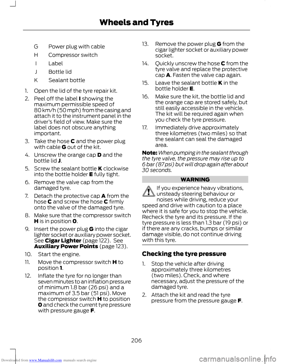
Downloaded from www.Manualslib.com manuals search engine Power plug with cable
G
Compressor switch
H
Label
I
Bottle lid
J
Sealant bottle
K
1. Open the lid of the tyre repair kit.
2. Peel off the label I showing the maximum permissible speed of
80 km/h (50 mph) from the casing and
attach it to the instrument panel in the
driver ’s field of view. Make sure the
label does not obscure anything
important.
3. Take the hose C and the power plug with cable G out of the kit.
4. Unscrew the orange cap D and the bottle lid J.
5. Screw the sealant bottle K clockwise into the bottle holder E fully tight.
6. Remove the valve cap from the damaged tyre.
7. Detach the protective cap A from the hose C and screw the hose C firmly
onto the valve of the damaged tyre.
8. Make sure that the compressor switch
H is in position 0.
9. Insert the power plug G into the cigar lighter socket or auxiliary power socket.
See Cigar Lighter (page 122). See
Auxiliary Power Points (page 123).
10. Start the engine.
11. Move the compressor switch H to position 1.
12. Inflate the tyre for no longer than seven minutes to an inflation pressure
of minimum 1.8 bar (26 psi) and a
maximum of 3.5 bar (51 psi). Move
the compressor switch H to position
0 and check the current tyre pressure
with pressure gauge F. 13. Remove the power plug G from the
cigar lighter socket or auxiliary power
socket.
14. Quickly unscrew the hose C from the
tyre valve and replace the protective
cap A. Fasten the valve cap again.
15. Leave the sealant bottle K in the bottle holder E.
16. Make sure the kit, the bottle lid and the orange cap are stored safely, but
still easily accessible in the vehicle.
The kit will be required again when
you check the tyre pressure.
17. Immediately drive approximately three kilometres (two miles) so that
the sealant can seal the damaged
area.
Note: When pumping in the sealant through
the tyre valve, the pressure may rise up to
6 bar (87 psi) but will drop again after about
30 seconds. WARNING
If you experience heavy vibrations,
unsteady steering behaviour or
noises while driving, reduce your
speed and drive with caution to a place
where it is safe for you to stop the vehicle.
Recheck the tyre and its pressure. If the
tyre pressure is less than 1.3 bar (19 psi) or
if there are any cracks, bumps or similar
damage visible, do not continue driving
with this tyre. Checking the tyre pressure
1. Stop the vehicle after driving
approximately three kilometres
(two miles). Check, and where
necessary, adjust the pressure of the
damaged tyre.
2. Attach the kit and read the tyre pressure from the pressure gauge F.
206
Wheels and Tyres