tow bar FORD C MAX 2011 2.G Owners Manual
[x] Cancel search | Manufacturer: FORD, Model Year: 2011, Model line: C MAX, Model: FORD C MAX 2011 2.GPages: 296, PDF Size: 7.87 MB
Page 119 of 296
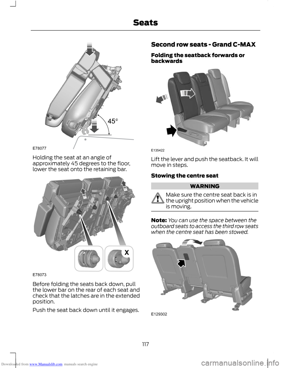
Downloaded from www.Manualslib.com manuals search engine Holding the seat at an angle of
approximately 45 degrees to the floor,
lower the seat onto the retaining bar.
Before folding the seats back down, pull
the lower bar on the rear of each seat and
check that the latches are in the extended
position.
Push the seat back down until it engages. Second row seats - Grand C-MAX
Folding the seatback forwards or
backwards
Lift the lever and push the seatback. It will
move in steps.
Stowing the centre seat
WARNING
Make sure the centre seat back is in
the upright position when the vehicle
is moving.
Note:
You can use the space between the
outboard seats to access the third row seats
when the centre seat has been stowed. 117
SeatsE78077 E78073X E135422 E129302
Page 151 of 296
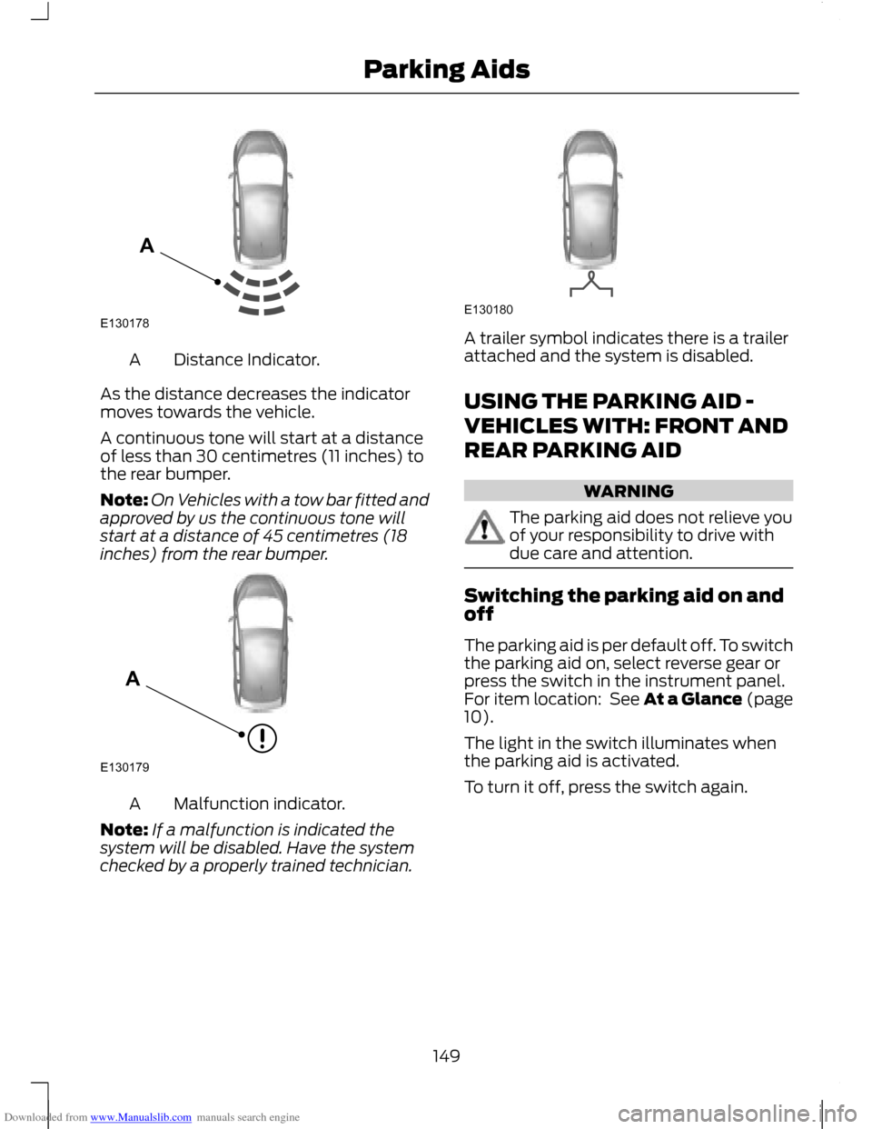
Downloaded from www.Manualslib.com manuals search engine Distance Indicator.
A
As the distance decreases the indicator
moves towards the vehicle.
A continuous tone will start at a distance
of less than 30 centimetres (11 inches) to
the rear bumper.
Note: On Vehicles with a tow bar fitted and
approved by us the continuous tone will
start at a distance of 45 centimetres (18
inches) from the rear bumper. Malfunction indicator.
A
Note: If a malfunction is indicated the
system will be disabled. Have the system
checked by a properly trained technician. A trailer symbol indicates there is a trailer
attached and the system is disabled.
USING THE PARKING AID -
VEHICLES WITH: FRONT AND
REAR PARKING AID
WARNING
The parking aid does not relieve you
of your responsibility to drive with
due care and attention.
Switching the parking aid on and
off
The parking aid is per default off. To switch
the parking aid on, select reverse gear or
press the switch in the instrument panel.
For item location: See At a Glance (page
10).
The light in the switch illuminates when
the parking aid is activated.
To turn it off, press the switch again.
149
Parking AidsE130178A E130179A E130180
Page 152 of 296
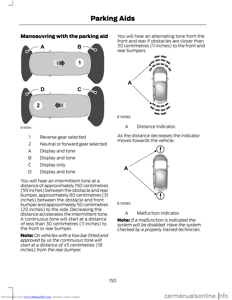
Downloaded from www.Manualslib.com manuals search engine Manoeuvring with the parking aid
Reverse gear selected
1
Neutral or forward gear selected
2
Display and tone
A
Display and tone
B
Display only
C
Display and tone
D
You will hear an intermittent tone at a
distance of approximately 150 centimetres
(59 inches) between the obstacle and rear
bumper, approximately 80 centimetres (31
inches) between the obstacle and front
bumper and approximately 50 centimetres
(20 inches) to the side. Decreasing the
distance accelerates the intermittent tone.
A continuous tone will start at a distance
of less than 30 centimetres (11 inches) to
the front or rear bumper.
Note: On vehicles with a tow bar fitted and
approved by us the continuous tone will
start at a distance of 45 centimetres (18
inches) from the rear bumper. You will hear an alternating tone from the
front and rear if obstacles are closer than
30 centimetres (11 inches) to the front and
rear bumpers.
Distance Indicator.
A
As the distance decreases the indicator
moves towards the vehicle. Malfuction indicator.
A
Note: If a malfunction is indicated the
system will be disabled. Have the system
checked by a properly trained technician.
150
Parking AidsE130381ABDC12 E130382A E130383A
Page 166 of 296
Downloaded from www.Manualslib.com manuals search engine Grand C-MAX
WARNING
Luggage retention net anchor points
are not fitted behind the first row
seats, but are fitted behind the
second row seats. Luggage retention net
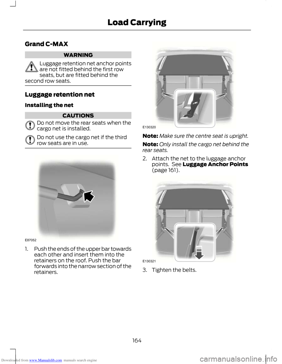
Installing the net
CAUTIONS
Do not move the rear seats when the
cargo net is installed.
Do not use the cargo net if the third
row seats are in use.
1.
Push the ends of the upper bar towards
each other and insert them into the
retainers on the roof. Push the bar
forwards into the narrow section of the
retainers. Note:
Make sure the centre seat is upright.
Note: Only install the cargo net behind the
rear seats.
2. Attach the net to the luggage anchor points. See Luggage Anchor Points
(page 161). 3. Tighten the belts.
164
Load CarryingE87052 E130320 E130321
Page 170 of 296
Downloaded from www.Manualslib.com manuals search engine TOWING A TRAILER
WARNINGS
Do not exceed 100 km/h (62 mph).
The rear tyre pressures must be
increased by 0.2 bar (3 psi) above
specification. See Technical
Specifications (page 209). Do not exceed the maximum gross
train weight stated on the vehicle
identification plate. See Vehicle
identification (page 214). CAUTION
Do not exceed the maximum
permissible nose weight, i.e. vertical
weight on the tow ball, of 75
kilogrammes (165 pounds). Note:
Not all vehicles are suitable or
approved to have tow bars fitted. Check
with your dealer first.
Place loads as low and central to the
axle(s) of the trailer as possible. If you are
towing with an unladen vehicle, the load
in the trailer should be placed toward the
nose, within the maximum nose load, as
this gives the best stability.
The stability of the vehicle to trailer
combination is very much dependant on
the quality of the trailer.
In high altitude regions above 1000 metres
(3281 feet), the stipulated maximum
permitted gross train weight must be
reduced by 10% for every additional 1000
metres (3281 feet).
Steep gradients WARNING
The overrun brake on a trailer is not
controlled by ABS. Change down a gear before you reach a
steep downhill gradient.
RETRACTABLE TOW BALL
CAUTION
Only move the tow ball arm with your
hand. Never use your foot or auxiliary
tools as damage to the mechanism
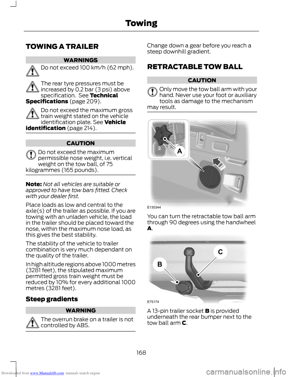
may result. You can turn the retractable tow ball arm
through 90 degrees using the handwheel
A.
A 13-pin trailer socket B is provided
underneath the rear bumper next to the
tow ball arm C.
168
TowingE130344A E75174BC
Page 171 of 296
Downloaded from www.Manualslib.com manuals search engine Swivelling the tow ball in
WARNINGS
Keep your hands away from the
handwheel as it rotates during the
locking process.
You will hear a warning tone when
the tow ball arm is not in one of the
locked positions. If you do not hear
the tone when moving the tow ball arm,
do not use the tow bar and have it checked
by a properly trained technician. CAUTION
Before retracting the ball neck into its
stowage position always unhitch the
trailer or dismantle load carriers and
their attachments. Dismantle attachments
for tracking stabilisation. Remove the plug
for the trailer power supply and the
adapter from the socket. Failure to do so
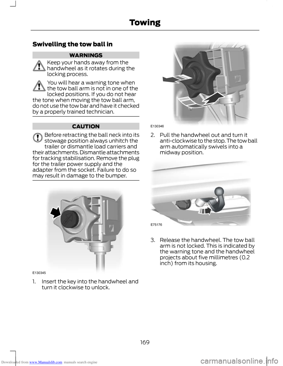
may result in damage to the bumper. 1. Insert the key into the handwheel and
turn it clockwise to unlock. 2. Pull the handwheel out and turn it
anti-clockwise to the stop. The tow ball
arm automatically swivels into a
midway position. 3. Release the handwheel. The tow ball
arm is not locked. This is indicated by
the warning tone and the handwheel
projects about five millimetres (0.2
inch) from its housing.
169
TowingE130345 E130346 E75176
Page 172 of 296
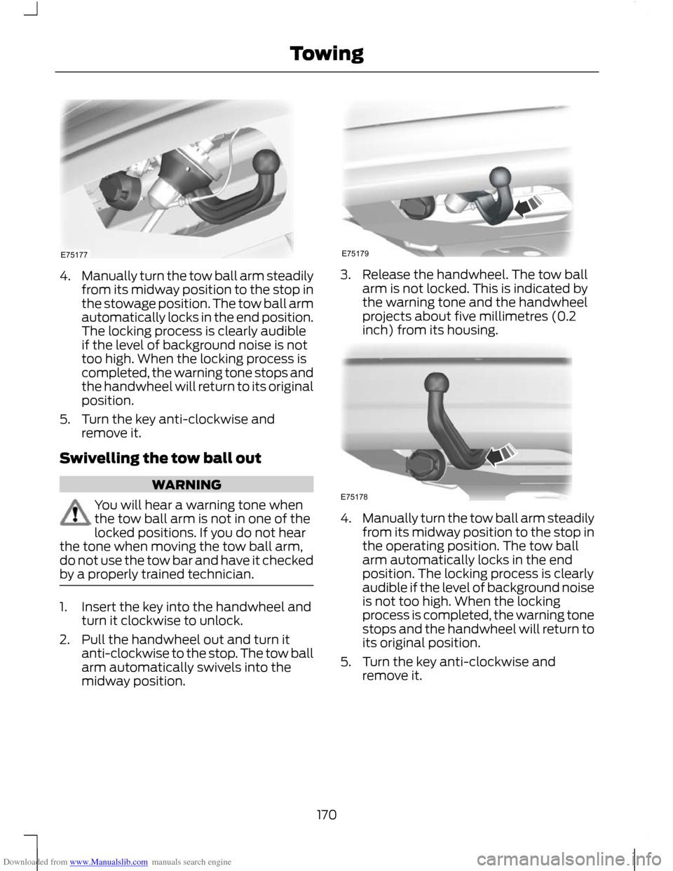
Downloaded from www.Manualslib.com manuals search engine 4.
Manually turn the tow ball arm steadily
from its midway position to the stop in
the stowage position. The tow ball arm
automatically locks in the end position.
The locking process is clearly audible
if the level of background noise is not
too high. When the locking process is
completed, the warning tone stops and
the handwheel will return to its original
position.
5. Turn the key anti-clockwise and remove it.
Swivelling the tow ball out WARNING
You will hear a warning tone when
the tow ball arm is not in one of the
locked positions. If you do not hear
the tone when moving the tow ball arm,
do not use the tow bar and have it checked
by a properly trained technician. 1. Insert the key into the handwheel and
turn it clockwise to unlock.
2. Pull the handwheel out and turn it anti-clockwise to the stop. The tow ball
arm automatically swivels into the
midway position. 3. Release the handwheel. The tow ball
arm is not locked. This is indicated by
the warning tone and the handwheel
projects about five millimetres (0.2
inch) from its housing. 4.
Manually turn the tow ball arm steadily
from its midway position to the stop in
the operating position. The tow ball
arm automatically locks in the end
position. The locking process is clearly
audible if the level of background noise
is not too high. When the locking
process is completed, the warning tone
stops and the handwheel will return to
its original position.
5. Turn the key anti-clockwise and remove it.
170
TowingE75177 E75179 E75178
Page 173 of 296
Downloaded from www.Manualslib.com manuals search engine Driving with a trailer
WARNING
If any of the conditions below cannot
be met, do not use the tow bar and
have it checked by a properly trained
technician. Before starting your journey, make sure
that the tow ball arm is properly locked.
Check that:
•
there is no warning tone when the
locking procedure has been completed
• the handwheel is in its housing and that
there is no gap
• you have locked the handwheel
(anti-clockwise) and removed the key
• the tow ball arm is locked. It must not
move when jerked.
Maintenance CAUTIONS
The towing hitch and control unit are
maintenance-free. Do not grease or
oil them.
Only the manufacturer should carry
out repairs or dismantle the towing
hitch.
If you use a high pressure spray to
wash your vehicle, do not direct the
spray onto the swivel joint of the tow
ball arm. 171
Towing
Page 185 of 296
Downloaded from www.Manualslib.com manuals search engine TOWING POINTS
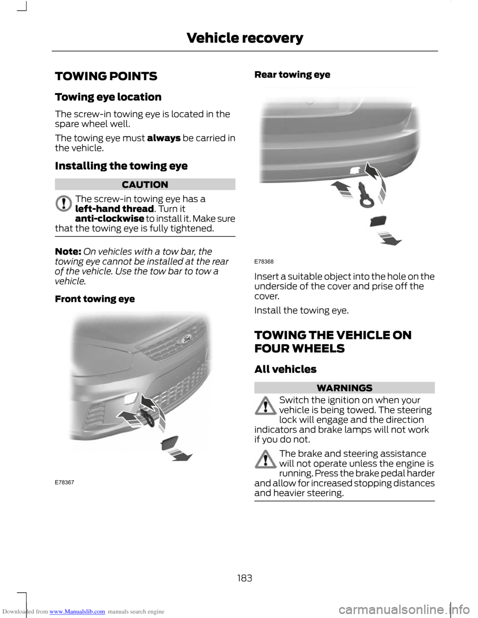
Towing eye location
The screw-in towing eye is located in the
spare wheel well.
The towing eye must always be carried in
the vehicle.
Installing the towing eye
CAUTION
The screw-in towing eye has a
left-hand thread. Turn it
anti-clockwise to install it. Make sure
that the towing eye is fully tightened. Note:
On vehicles with a tow bar, the
towing eye cannot be installed at the rear
of the vehicle. Use the tow bar to tow a
vehicle.
Front towing eye Rear towing eye
Insert a suitable object into the hole on the
underside of the cover and prise off the
cover.
Install the towing eye.
TOWING THE VEHICLE ON
FOUR WHEELS
All vehicles
WARNINGS
Switch the ignition on when your
vehicle is being towed. The steering
lock will engage and the direction
indicators and brake lamps will not work
if you do not. The brake and steering assistance
will not operate unless the engine is
running. Press the brake pedal harder
and allow for increased stopping distances
and heavier steering. 183
Vehicle recoveryE78367 E78368
Page 291 of 296
Downloaded from www.Manualslib.com manuals search engine Opening and Closing the Bonnet...........185
Closing the bonnet............................................ 186
Opening the bonnet.......................................... 185
P
Parking Aids....................................................148 Principle of Operation....................................... 148
Parking Brake.................................................144
Parts and Accessories.....................................7 Look for the Ford logo on the following
parts ....................................................................... 8
Now you can be sure that your Ford parts are Ford parts....................................................... 7
Personalised Settings..................................89 Chime deactivation............................................. 90
Language setting................................................. 89
Measure units........................................................ 90
Temperature units............................................... 90
Power Door Locks See: Locking and Unlocking............................. 39
Power Seats......................................................111
Power Windows...............................................71 Anti-trap function.................................................. 71
Driver's door switches.......................................... 71
Global opening and closing............................... 71
Opening and closing the windows automatically..................................................... 71
Resetting the memory of the electric windows.............................................................. 72
Safety switch for rear windows........................ 71
Programming the remote control............36 Programming a new remote control............36
Reprogramming the unlocking
function............................................................... 36
R
Rear Fog Lamps.............................................58
Rear Seats........................................................112 Second row seats - C-MAX.............................. 112
Second row seats - Grand C-MAX.................117
Third row seats - Grand C-MAX..................... 119
Rear Under Floor Storage..........................163
Rear view camera.........................................155 Principle of Operation....................................... 155Rear Window Wiper and Washers...........53
Intermittent wipe.................................................. 53
Rear window washer.......................................... 54
Reverse gear wipe................................................ 54
Refuelling........................................................138
Regional mode (REG).................................231
Remote control battery See: Changing the remote control
battery................................................................. 36
Remote control programming See: Programming the remote control........36
Removing a Headlamp................................62
Repairing Minor Paint Damage...............196
Repeat compact disc tracks....................232 Type 1...................................................................... 232
Type 2 and 3......................................................... 232
Retractable tow ball...................................168 Driving with a trailer............................................ 171
Maintenance.......................................................... 171
Swivelling the tow ball in................................ 169
Swivelling the tow ball out.............................. 170
Road Safety...................................................262 Safety information............................................ 263
Roadside Emergencies...............................173
Roof Racks and Load Carriers.................165 Installing the crossbars.................................... 165
Roof rack................................................................ 165
Route displays...............................................276 Junction zoom..................................................... 276
Map display.......................................................... 276
Navigation display............................................. 276
Route options menu...................................275 Driver....................................................................... 275
Dynamic................................................................. 275
Eco settings.......................................................... 275
Ferry/motorail...................................................... 275
Motorway.............................................................. 275
Route....................................................................... 275
Seasonal roads................................................... 276
Toll........................................................................\
... 275
Toll sticker............................................................. 276
Running-In.......................................................172 Brakes and clutch................................................ 172
Engine...................................................................... 172
Tyres........................................................................\
. 172
289
Index