clock FORD C MAX ENERGI 2016 Owners Manual
[x] Cancel search | Manufacturer: FORD, Model Year: 2016, Model line: C MAX ENERGI, Model: FORD C MAX ENERGI 2016Pages: 395, PDF Size: 6.78 MB
Page 20 of 395
Use a child safety seat (sometimes calledan infant carrier, convertible seat, ortoddler seat) for infants, toddlers, orchildren weighing 40 pounds (18kilograms) or less (generally age four oryounger).
Using Lap and Shoulder Belts
WARNINGS
Airbags can kill or injure a child in achild seat. Never place a rear-facingchild seat in front of an active airbag.If you must use a forward-facing child seatin the front seat, move the seat all the wayback.
Airbags can kill or injure a child in achild seat. Children 12 and undershould be properly restrained in therear seat whenever possible.
Depending on where you secure achild restraint, and depending on thechild restraint design, you may blockaccess to certain safety belt buckleassemblies and LATCH lower anchors,rendering those features potentiallyunusable. To avoid risk of injury, occupantsshould only use seating positions wherethey are able to be properly restrained.
When installing a child safety seat withcombination lap and shoulder belts:
•Use the correct safety belt buckle forthat seating position.
•Insert the belt tongue into the properbuckle until you hear a snap and feel itlatch. Make sure the tongue is securelyfastened in the buckle.
•Keep the buckle release buttonpointing up and away from the safetyseat, with the tongue between the childseat and the release button, to preventaccidental unbuckling.
•Place the vehicle seat upon which thechild seat will be installed in the uprightposition.
•Put the safety belt in the automaticlocking mode. See Step 5. This vehicledoes not require the use of a lockingclip.
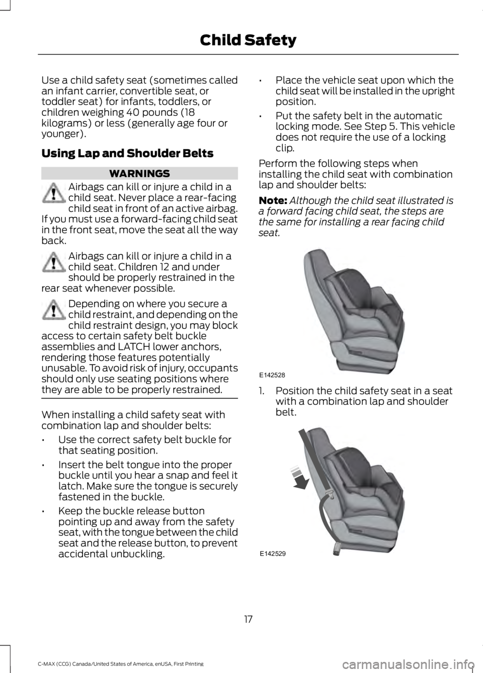
Perform the following steps wheninstalling the child seat with combinationlap and shoulder belts:
Note:Although the child seat illustrated isa forward facing child seat, the steps arethe same for installing a rear facing childseat.
1. Position the child safety seat in a seatwith a combination lap and shoulderbelt.
17
C-MAX (CCG) Canada/United States of America, enUSA, First Printing
Child SafetyE142528 E142529
Page 21 of 395
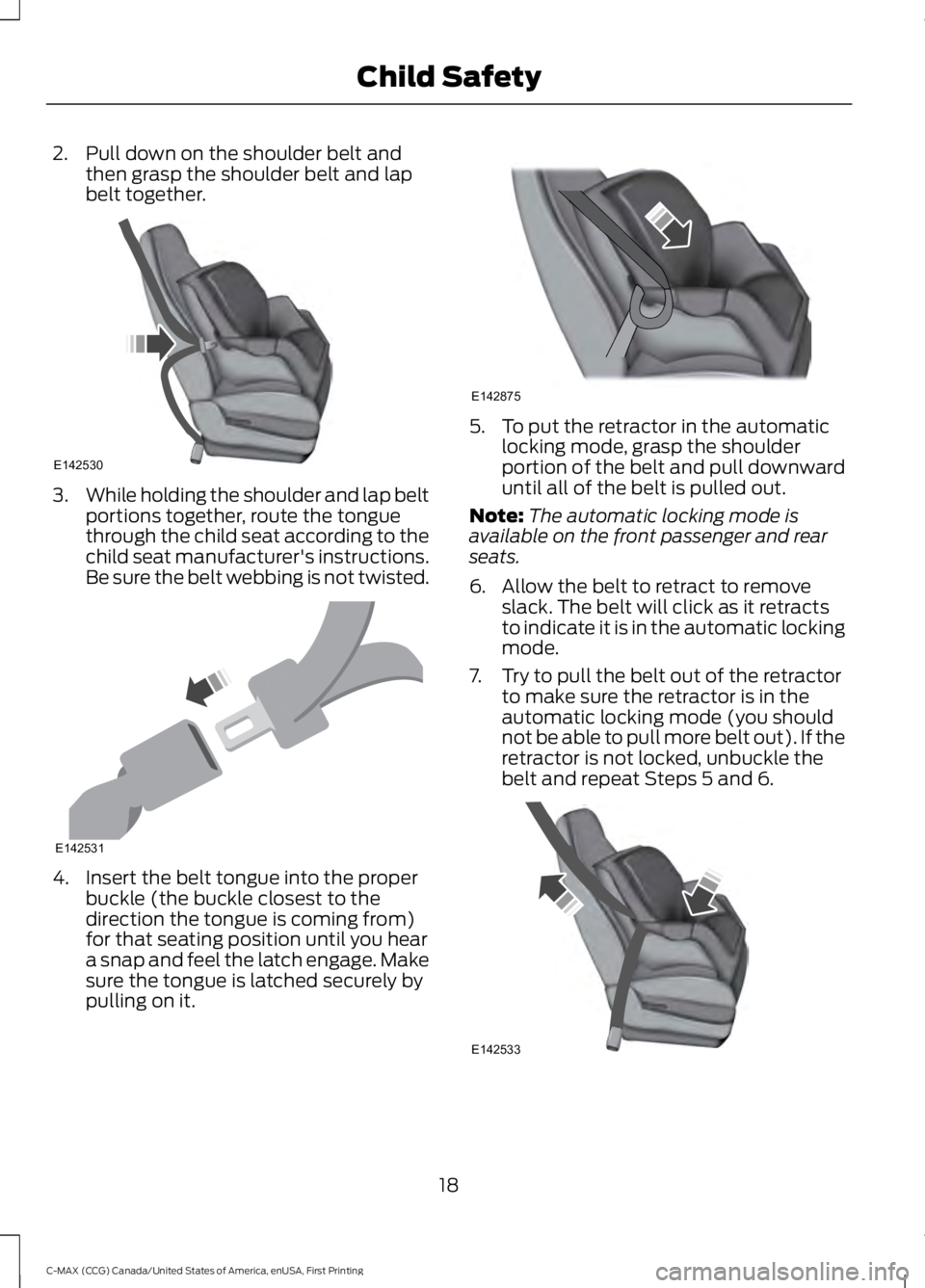
2. Pull down on the shoulder belt andthen grasp the shoulder belt and lapbelt together.
3.While holding the shoulder and lap beltportions together, route the tonguethrough the child seat according to thechild seat manufacturer's instructions.Be sure the belt webbing is not twisted.
4. Insert the belt tongue into the properbuckle (the buckle closest to thedirection the tongue is coming from)for that seating position until you heara snap and feel the latch engage. Makesure the tongue is latched securely bypulling on it.
5. To put the retractor in the automaticlocking mode, grasp the shoulderportion of the belt and pull downwarduntil all of the belt is pulled out.
Note:The automatic locking mode isavailable on the front passenger and rearseats.
6. Allow the belt to retract to removeslack. The belt will click as it retractsto indicate it is in the automatic lockingmode.
7. Try to pull the belt out of the retractorto make sure the retractor is in theautomatic locking mode (you shouldnot be able to pull more belt out). If theretractor is not locked, unbuckle thebelt and repeat Steps 5 and 6.
18
C-MAX (CCG) Canada/United States of America, enUSA, First Printing
Child SafetyE142530 E142531 E142875 E142533
Page 29 of 395
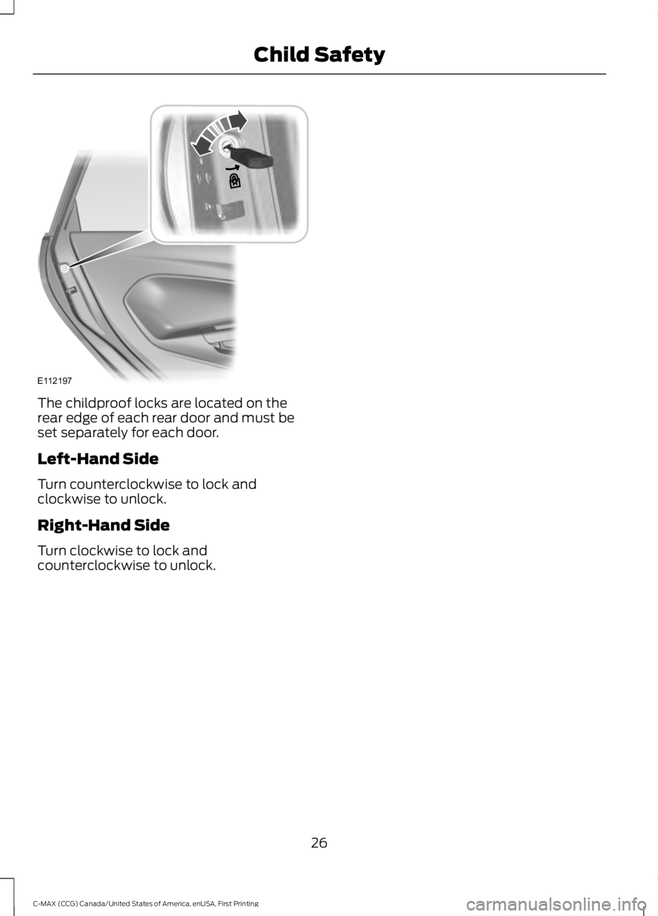
The childproof locks are located on therear edge of each rear door and must beset separately for each door.
Left-Hand Side
Turn counterclockwise to lock andclockwise to unlock.
Right-Hand Side
Turn clockwise to lock andcounterclockwise to unlock.
26
C-MAX (CCG) Canada/United States of America, enUSA, First Printing
Child SafetyE112197
Page 30 of 395
PRINCIPLE OF OPERATION
WARNINGS
Always drive and ride with yourseatback upright and the lap beltsnug and low across the hips.
To reduce the risk of injury, makesure children sit where they can beproperly restrained.
Never let a passenger hold a child onhis or her lap while your vehicle ismoving. The passenger cannotprotect the child from injury in a crash.
All occupants of your vehicle,including the driver, should alwaysproperly wear their safety belts, evenwhen an airbag supplemental restraintsystem is provided.
It is extremely dangerous to ride in acargo area, inside or outside of avehicle. In a crash, people riding inthese areas are more likely to be seriouslyinjured or killed. Do not allow people to ridein any area of your vehicle that is notequipped with seats and safety belts. Besure everyone in your vehicle is in a seatand using a safety belt properly.
In a rollover crash, an unbeltedperson is significantly more likely todie than a person wearing a safetybelt.
Each seating position in your vehiclehas a specific safety belt assemblywhich is made up of one buckle andone tongue that are designed to be usedas a pair. 1) Use the shoulder belt on theoutside shoulder only. Never wear theshoulder belt under the arm. 2) Neverswing the safety belt around your neck overthe inside shoulder. 3) Never use a singlebelt for more than one person.
When possible, all children 12 yearsold and under should be properlyrestrained in a rear seating position.
WARNINGS
Safety belts and seats can becomehot in a vehicle that has been closedup in sunny weather; they could burna small child. Check seat covers andbuckles before you place a child anywherenear them.
Front and rear seat occupants,including pregnant women, shouldwear safety belts for optimumprotection in an accident.
All seating positions in this vehicle havelap and shoulder safety belts. Alloccupants of the vehicle should alwaysproperly wear their safety belts, even whenan airbag supplemental restraint systemis provided.
The safety belt system consists of:
•lap and shoulder safety belts
•shoulder safety belt with automaticlocking mode, (except driver safetybelt)
•height adjuster at the front outboardseating positions
•retractor and anchor pretensioner atthe front outboard seating positions
•belt tension sensor at the frontoutboard passenger seating position
•safety belt warning light and chime
•crash sensors and monitoring systemwith readiness indicator.
27
C-MAX (CCG) Canada/United States of America, enUSA, First Printing
Seatbelts
Page 33 of 395
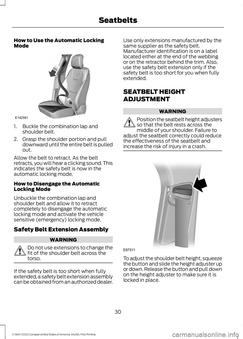
How to Use the Automatic LockingMode
1. Buckle the combination lap andshoulder belt.
2. Grasp the shoulder portion and pulldownward until the entire belt is pulledout.
Allow the belt to retract. As the beltretracts, you will hear a clicking sound. Thisindicates the safety belt is now in theautomatic locking mode.
How to Disengage the AutomaticLocking Mode
Unbuckle the combination lap andshoulder belt and allow it to retractcompletely to disengage the automaticlocking mode and activate the vehiclesensitive (emergency) locking mode.
Safety Belt Extension Assembly
WARNING
Do not use extensions to change thefit of the shoulder belt across thetorso.
If the safety belt is too short when fullyextended, a safety belt extension assemblycan be obtained from an authorized dealer.
Use only extensions manufactured by thesame supplier as the safety belt.Manufacturer identification is on a labellocated either at the end of the webbingor on the retractor behind the trim. Also,use the safety belt extension only if thesafety belt is too short for you when fullyextended.
SEATBELT HEIGHT
ADJUSTMENT
WARNING
Position the seatbelt height adjustersso that the belt rests across themiddle of your shoulder. Failure toadjust the seatbelt correctly could reducethe effectiveness of the seatbelt andincrease the risk of injury in a crash.
To adjust the shoulder belt height, squeezethe button and slide the height adjuster upor down. Release the button and pull downon the height adjuster to make sure it islocked in place.
30
C-MAX (CCG) Canada/United States of America, enUSA, First Printing
SeatbeltsE142591 E87511
Page 60 of 395
WARNINGS
Make sure to close and latch theliftgate to prevent drawing exhaustfumes into your vehicle. This will alsoprevent passengers and cargo from fallingout. If you must drive with the liftgate open,keep the vents or windows open so outsideair comes into your vehicle. Failure tofollow this warning could result in seriouspersonal injury.
Note:Be careful when opening or closingthe liftgate in a garage or other enclosedarea to avoid damaging the liftgate.
Press twice within three secondsto:
•unlatch a manual liftgate
•open, close or stop the movement ofa power liftgate. See Power Liftgate(page 61).
Mechanical Key
Turn the top of the key toward the front ofyour vehicle once to lock all doors.
Turn the top of the key toward the rear ofyour vehicle once to unlock the driver dooronly.
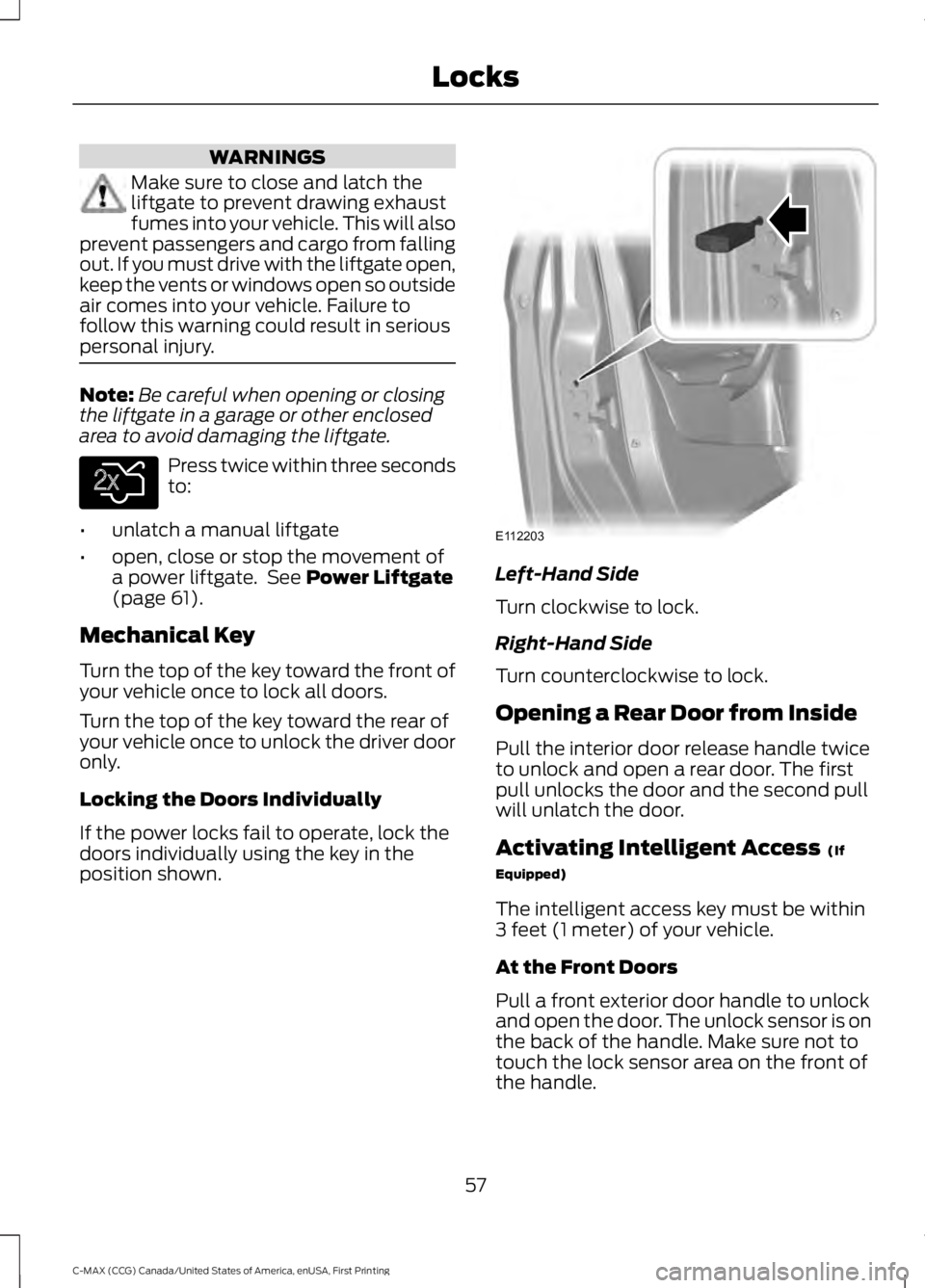
Locking the Doors Individually
If the power locks fail to operate, lock thedoors individually using the key in theposition shown.
Left-Hand Side
Turn clockwise to lock.
Right-Hand Side
Turn counterclockwise to lock.
Opening a Rear Door from Inside
Pull the interior door release handle twiceto unlock and open a rear door. The firstpull unlocks the door and the second pullwill unlatch the door.
Activating Intelligent Access (If
Equipped)
The intelligent access key must be within3 feet (1 meter) of your vehicle.
At the Front Doors
Pull a front exterior door handle to unlockand open the door. The unlock sensor is onthe back of the handle. Make sure not totouch the lock sensor area on the front ofthe handle.
57
C-MAX (CCG) Canada/United States of America, enUSA, First Printing
LocksE138630 E112203
Page 161 of 395
Charge Port
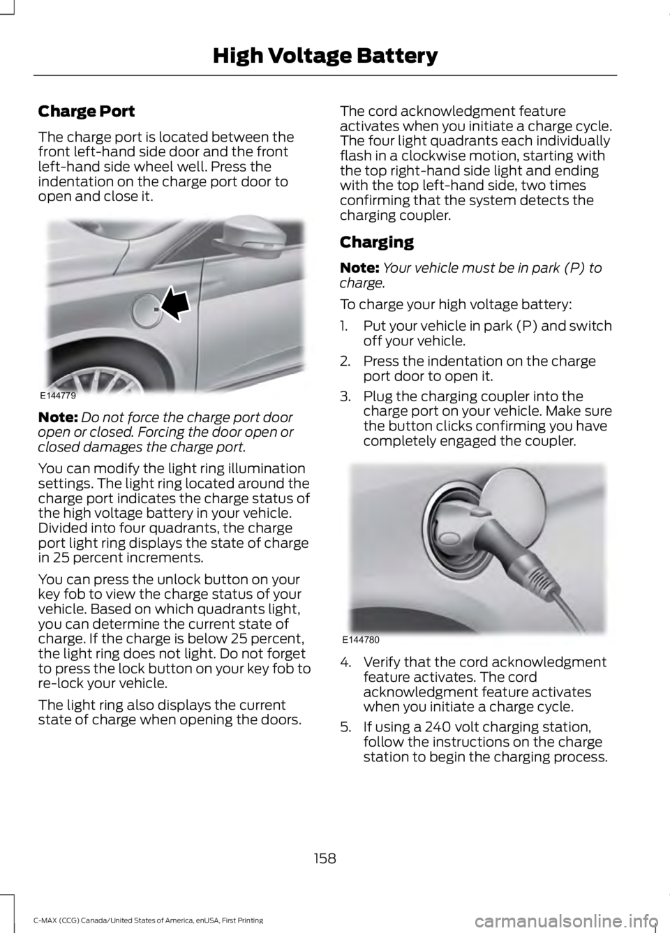
The charge port is located between thefront left-hand side door and the frontleft-hand side wheel well. Press theindentation on the charge port door toopen and close it.
Note:Do not force the charge port dooropen or closed. Forcing the door open orclosed damages the charge port.
You can modify the light ring illuminationsettings. The light ring located around thecharge port indicates the charge status ofthe high voltage battery in your vehicle.Divided into four quadrants, the chargeport light ring displays the state of chargein 25 percent increments.
You can press the unlock button on yourkey fob to view the charge status of yourvehicle. Based on which quadrants light,you can determine the current state ofcharge. If the charge is below 25 percent,the light ring does not light. Do not forgetto press the lock button on your key fob tore-lock your vehicle.
The light ring also displays the currentstate of charge when opening the doors.
The cord acknowledgment featureactivates when you initiate a charge cycle.The four light quadrants each individuallyflash in a clockwise motion, starting withthe top right-hand side light and endingwith the top left-hand side, two timesconfirming that the system detects thecharging coupler.
Charging
Note:Your vehicle must be in park (P) tocharge.
To charge your high voltage battery:
1.Put your vehicle in park (P) and switchoff your vehicle.
2. Press the indentation on the chargeport door to open it.
3. Plug the charging coupler into thecharge port on your vehicle. Make surethe button clicks confirming you havecompletely engaged the coupler.
4. Verify that the cord acknowledgmentfeature activates. The cordacknowledgment feature activateswhen you initiate a charge cycle.
5. If using a 240 volt charging station,follow the instructions on the chargestation to begin the charging process.
158
C-MAX (CCG) Canada/United States of America, enUSA, First Printing
High Voltage BatteryE144779 E144780
Page 163 of 395
Disconnecting the ChargingCoupler
Note:Do not pull the wall plug from thewall while the vehicle is charging. Doing somay damage the outlet and the cord.
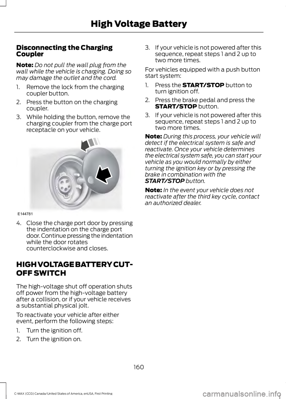
1. Remove the lock from the chargingcoupler button.
2. Press the button on the chargingcoupler.
3. While holding the button, remove thecharging coupler from the charge portreceptacle on your vehicle.
4.Close the charge port door by pressingthe indentation on the charge portdoor. Continue pressing the indentationwhile the door rotatescounterclockwise and closes.
HIGH VOLTAGE BATTERY CUT-
OFF SWITCH
The high-voltage shut off operation shutsoff power from the high-voltage batteryafter a collision, or if your vehicle receivesa substantial physical jolt.
To reactivate your vehicle after eitherevent, perform the following steps:
1. Turn the ignition off.
2. Turn the ignition on.
3.If your vehicle is not powered after thissequence, repeat steps 1 and 2 up totwo more times.
For vehicles equipped with a push buttonstart system:
1. Press the START/STOP button toturn ignition off.
2. Press the brake pedal and press theSTART/STOP button.
3.If your vehicle is not powered after thissequence, repeat steps 1 and 2 up totwo more times.
Note:During this process, your vehicle willdetect if the electrical system is safe andreactivate. Once your vehicle determinesthe electrical system safe, you can start yourvehicle as you would normally by eitherturning the ignition key or by pressing thebrake in combination with theSTART/STOP button.
Note:In the event your vehicle does notreactivate after the third key cycle, contactan authorized dealer.
160
C-MAX (CCG) Canada/United States of America, enUSA, First Printing
High Voltage BatteryE144781
Page 231 of 395
CHANGING THE 12V BATTERY
WARNINGS
Batteries normally produce explosivegases which can cause personalinjury. Therefore, do not allowflames, sparks or lighted substances tocome near the battery. When working nearthe battery, always shield your face andprotect your eyes. Always provide correctventilation.
When lifting a plastic-cased battery,excessive pressure on the end wallscould cause acid to flow through thevent caps, resulting in personal injury anddamage to the vehicle or battery. Lift thebattery with a battery carrier or with yourhands on opposite corners.
Keep batteries out of reach ofchildren. Batteries contain sulfuricacid. Avoid contact with skin, eyes orclothing. Shield your eyes when workingnear the battery to protect against possiblesplashing of acid solution. In case of acidcontact with skin or eyes, flushimmediately with water for a minimum of15 minutes and get prompt medicalattention. If acid is swallowed, call aphysician immediately.
Battery posts, terminals and relatedaccessories contain lead and leadcompounds. Wash hands afterhandling.
Your vehicle has a Motorcraft®maintenance-free battery which normallydoes not require additional water duringits life of service.
Note:If your vehicle's battery has a coveror shield, make sure it is reinstalled after thebattery has been cleaned or replaced.
Note:See an authorized dealer for lowvoltage battery access, testing, orreplacement.
When a low voltage battery replacementis necessary, see an authorized dealer toreplace the low voltage battery with a Fordrecommended replacement low voltagebattery that matches the electricalrequirements of the vehicle.
To ensure proper operation of the batterymanagement system (BMS), do not allowa technician to connect any electricaldevice ground connection directly to thelow voltage battery negative post. Aconnection at the low voltage batterynegative post can cause inaccuratemeasurements of the battery conditionand potential incorrect system operation.
Note:If a person adds electrical orelectronic accessories or components to thevehicle, the accessories or components mayadversely affect the low voltage batteryperformance and durability and may alsoaffect the performance of other electricalsystems in the vehicle.
For longer, trouble-free operation, keep thetop of the battery clean and dry. Also,make certain the battery cables are alwaystightly fastened to the battery terminals.
If you see any corrosion on the battery orterminals, remove the cables from theterminals and clean with a wire brush. Youcan neutralize the acid with a solution ofbaking soda and water.
When a battery replacement is required,the battery should only be replaced witha Ford recommended replacement batterythat matches the electrical requirementsof the vehicle.
Because your vehicle’s engine iselectronically-controlled by a computer,some engine control settings aremaintained by power from the low voltagebattery. Some engine computer settings,like the idle trim and fuel trim strategy,optimize the driveability and performanceof the engine. Some other computersettings, like the clock and radio station
228
C-MAX (CCG) Canada/United States of America, enUSA, First Printing
Maintenance
Page 232 of 395
presets, are also maintained in memory bypower from the low voltage battery. Whena technician disconnects and connects thelow voltage battery, these settings areerased. Complete the following procedurein order to restore the settings:
1. With the vehicle at a complete stop,set the parking brake.
2. Shift into park (P).
3. Switch off all accessories.
4. Fully press the brake pedal and startthe vehicle.
5. Run the engine until it reaches normaloperating temperature. While theengine is warming up, complete thefollowing: Reset the clock. See AudioSystem (page 283). Reset the powerwindows bounce-back feature. SeeWindows and Mirrors (page 80).Reset the radio station presets. SeeAudio System (page 283).
6.Allow the engine to idle for at least oneminute. If the engine turns off, pressthe accelerator pedal to start theengine.
7. While the engine is running, press thebrake pedal and shift into neutral (N).
8.Allow the engine to run for at least oneminute by pressing on the acceleratorpedal.
9.Drive the vehicle at least 12 mi (20 km)to completely relearn the idle and fueltrim strategy.
Note:If you do not allow the engine torelearn the idle and fuel trim strategy, theidle quality of your vehicle may be adverselyaffected until the engine computereventually relearns the idle trim and fueltrim strategy.
Make sure that you dispose of old batteriesin an environmentally friendly way. Seekadvice from your local authority aboutrecycling old batteries.
CHECKING THE WIPER
BLADES
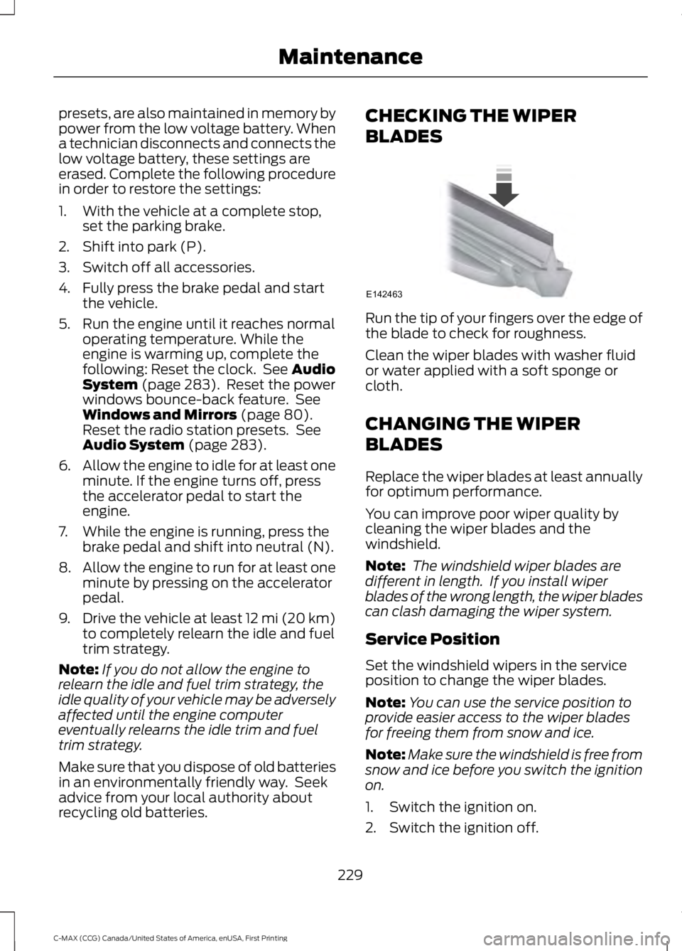
Run the tip of your fingers over the edge ofthe blade to check for roughness.
Clean the wiper blades with washer fluidor water applied with a soft sponge orcloth.
CHANGING THE WIPER
BLADES
Replace the wiper blades at least annuallyfor optimum performance.
You can improve poor wiper quality bycleaning the wiper blades and thewindshield.
Note: The windshield wiper blades aredifferent in length. If you install wiperblades of the wrong length, the wiper bladescan clash damaging the wiper system.
Service Position
Set the windshield wipers in the serviceposition to change the wiper blades.
Note:You can use the service position toprovide easier access to the wiper bladesfor freeing them from snow and ice.
Note:Make sure the windshield is free fromsnow and ice before you switch the ignitionon.
1. Switch the ignition on.
2. Switch the ignition off.
229
C-MAX (CCG) Canada/United States of America, enUSA, First Printing
MaintenanceE142463