warning light FORD C MAX HYBRID 2014 2.G Owner's Guide
[x] Cancel search | Manufacturer: FORD, Model Year: 2014, Model line: C MAX HYBRID, Model: FORD C MAX HYBRID 2014 2.GPages: 447, PDF Size: 8.06 MB
Page 192 of 447
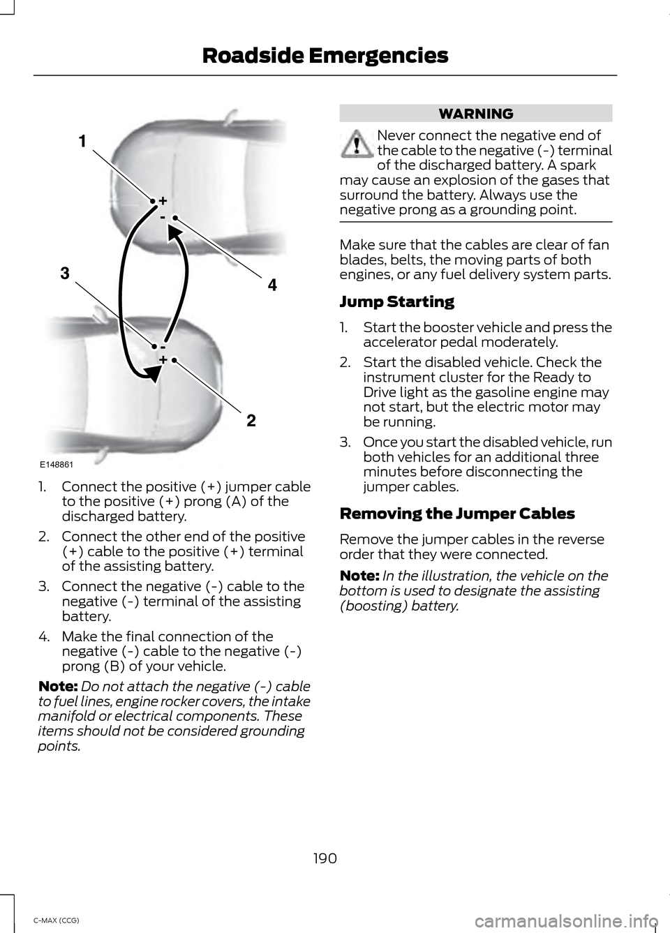
1.
Connect the positive (+) jumper cable
to the positive (+) prong (A) of the
discharged battery.
2. Connect the other end of the positive (+) cable to the positive (+) terminal
of the assisting battery.
3. Connect the negative (-) cable to the negative (-) terminal of the assisting
battery.
4. Make the final connection of the negative (-) cable to the negative (-)
prong (B) of your vehicle.
Note: Do not attach the negative (-) cable
to fuel lines, engine rocker covers, the intake
manifold or electrical components. These
items should not be considered grounding
points. WARNING
Never connect the negative end of
the cable to the negative (-) terminal
of the discharged battery. A spark
may cause an explosion of the gases that
surround the battery. Always use the
negative prong as a grounding point. Make sure that the cables are clear of fan
blades, belts, the moving parts of both
engines, or any fuel delivery system parts.
Jump Starting
1.
Start the booster vehicle and press the
accelerator pedal moderately.
2. Start the disabled vehicle. Check the instrument cluster for the Ready to
Drive light as the gasoline engine may
not start, but the electric motor may
be running.
3. Once you start the disabled vehicle, run
both vehicles for an additional three
minutes before disconnecting the
jumper cables.
Removing the Jumper Cables
Remove the jumper cables in the reverse
order that they were connected.
Note: In the illustration, the vehicle on the
bottom is used to designate the assisting
(boosting) battery.
190
C-MAX (CCG) Roadside EmergenciesE148861
Page 212 of 447
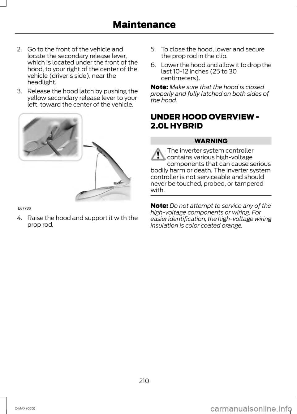
2. Go to the front of the vehicle and
locate the secondary release lever,
which is located under the front of the
hood, to your right of the center of the
vehicle (driver's side), near the
headlight.
3. Release the hood latch by pushing the yellow secondary release lever to your
left, toward the center of the vehicle. 4.
Raise the hood and support it with the
prop rod. 5. To close the hood, lower and secure
the prop rod in the clip.
6. Lower the hood and allow it to drop the
last 10-12 inches (25 to 30
centimeters).
Note: Make sure that the hood is closed
properly and fully latched on both sides of
the hood.
UNDER HOOD OVERVIEW -
2.0L HYBRID WARNING
The inverter system controller
contains various high-voltage
components that can cause serious
bodily harm or death. The inverter system
controller is not serviceable and should
never be touched, probed, or tampered
with. Note:
Do not attempt to service any of the
high-voltage components or wiring. For
easier identification, the high-voltage wiring
insulation is color coated orange.
210
C-MAX (CCG) MaintenanceE87786
Page 216 of 447
Note:
For best results, coolant
concentration should be tested with a
refractometer such as Rotunda tool
300-ROB75240 available from your dealer.
Ford does not recommend the use of
hydrometers or coolant test strips for
measuring coolant concentrations.
Note: Automotive fluids are not
interchangeable. Do not use engine coolant
or antifreeze or windshield washer fluid
outside of its specified function and vehicle
location.
Adding Coolant WARNINGS
Do not add engine coolant when the
engine is hot. Steam and scalding
liquids released from a hot cooling
system can burn you badly. Also, you can
be burned if you spill coolant on hot engine
parts. Do not put engine coolant in the
windshield washer fluid container. If
sprayed on the windshield, engine
coolant could make it difficult to see
through the windshield. To reduce the risk of personal injury,
make sure the engine is cool before
unscrewing the coolant pressure
relief cap. The cooling system is under
pressure; steam and hot liquid can come
out forcefully when the cap is loosened
slightly. Do not add coolant further than the
MAX mark.
Note:
Do not use stop leak pellets, cooling
system sealants, or additives as they can
cause damage to the cooling or heating
systems. This damage would not be covered
under your vehicle ’s warranty. Note:
During normal vehicle operation, the
coolant may change color from orange to
pink or light red. As long as the coolant is
clear and uncontaminated, this color change
does not indicate the coolant has degraded
nor does it require the coolant to be drained,
the system to be flushed, or the coolant to
be replaced.
Note: It is very important to use prediluted
coolant meeting the Ford specification in
order to avoid plugging the small coolant
passageways. Use of concentrated coolant
and water may cause coolant passageway
plugging and void the warranty. See
Capacities and Specifications (page 265).
• Do not mix different colors or types of
coolant in your vehicle. Make sure the
correct coolant is used. Mixing of
coolants may harm your cooling
system. The use of an improper coolant
may harm the engine, inverter system
controller, and cooling system
components and may void the
warranty.
• In case of emergency, a large amount
of water without engine coolant may
be added to the engine cooling system
only in order to reach a vehicle service
location. In this instance, the engine
cooling system must be drained,
chemically cleaned with Motorcraft
Premium Cooling System Flush, and
refilled with prediluted engine coolant
as soon as possible. Water alone
(without engine coolant) can cause
engine damage from corrosion,
overheating, or freezing. DO NOT use
this method for the inverter system
controller cooling system. The inverter
system controller cooling system
operates close to ambient
temperature, and is susceptible to
freezing in any subfreezing environment
in the absence of coolant.
214
C-MAX (CCG) Maintenance
Page 218 of 447
Vehicles driven year-round in non-extreme
climates should use prediluted coolant
meeting the Ford specification for
optimum cooling system and engine
protection.
What You Should Know About Fail-
Safe Cooling
If the engine coolant supply is depleted,
this feature allows the vehicle to be driven
temporarily before incremental component
damage is incurred. The
“fail-safe”
distance depends on ambient
temperatures, vehicle load and terrain.
How Fail-Safe Cooling Works
If the engine begins to overheat, the engine
coolant temperature gauge will move to
the red (hot) area and: The coolant temperature
warning light will illuminate.
The service engine soon
indicator will illuminate.
If the engine reaches a preset
over-temperature condition, the engine
will automatically switch to alternating
cylinder operation. Each disabled cylinder
acts as an air pump and cools the engine.
When this occurs the vehicle will still
operate. However:
• The engine power will be limited.
• The air conditioning system will be
disabled.
Continued operation will increase the
engine temperature and the engine will
completely shut down, causing steering
and braking effort to increase.
Once the engine temperature cools, the
engine can be re-started. Take your vehicle
to an authorized dealer as soon as possible
to minimize engine damage. When Fail-Safe Mode Is Activated WARNINGS
Fail-safe mode is for use during
emergencies only. Operate the
vehicle in fail-safe mode only as long
as necessary to bring the vehicle to rest in
a safe location and seek immediate repairs.
When in fail-safe mode, the vehicle will
have limited power, will not be able to
maintain high-speed operation, and may
completely shut down without warning,
potentially losing engine power, power
steering assist, and power brake assist,
which may increase the possibility of a
crash resulting in serious injury. Never remove the coolant reservoir
cap while the engine is running or hot.
Note:
Driving the vehicle without repairing
the engine problem increases the chance of
engine damage. Take your vehicle to an
authorized dealer as soon as possible.
You have limited engine power when in the
fail-safe mode, so drive the vehicle with
caution. The vehicle will not be able to
maintain high-speed operation and the
engine will run rough. Remember that the
engine is capable of completely shutting
down automatically to prevent engine
damage, therefore:
1. Pull off the road as soon as safely possible and turn off the engine.
2. Arrange for the vehicle to be taken to an authorized dealer.
3. If this is not possible, wait a short period for the engine to cool.
4. Check the coolant level and replenish if low.
5. Re-start the engine and take your vehicle to an authorized dealer.
216
C-MAX (CCG) Maintenance
Page 220 of 447
CHANGING THE 12V BATTERY
WARNINGS
Batteries normally produce explosive
gases which can cause personal
injury. Therefore, do not allow
flames, sparks or lighted substances to
come near the battery. When working near
the battery, always shield your face and
protect your eyes. Always provide proper
ventilation. When lifting a plastic-cased battery,
excessive pressure on the end walls
could cause acid to flow through the
vent caps, resulting in personal injury and
damage to the vehicle or battery. Lift the
battery with a battery carrier or with your
hands on opposite corners. Keep batteries out of reach of
children. Batteries contain sulfuric
acid. Avoid contact with skin, eyes or
clothing. Shield your eyes when working
near the battery to protect against possible
splashing of acid solution. In case of acid
contact with skin or eyes, flush
immediately with water for a minimum of
15 minutes and get prompt medical
attention. If acid is swallowed, call a
physician immediately. Your vehicle is equipped with a
Motorcraft® maintenance-free battery
which normally does not require additional
water during its life of service.
Note:
If your battery has a cover/shield,
make sure it is reinstalled after the battery
has been cleaned or replaced.
Note: See an authorized dealer for low
voltage battery access, testing, or
replacement. When a low voltage battery replacement
is necessary, see an authorized dealer to
replace the low voltage battery with a Ford
recommended replacement low voltage
battery that matches the electrical
requirements of the vehicle
To ensure proper operation of the battery
management system (BMS), do not allow
a technician to connect any electrical
device ground connection directly to the
low voltage battery negative post. A
connection at the low voltage battery
negative post can cause inaccurate
measurements of the battery condition
and potential incorrect system operation.
Note:
If a person adds electrical or
electronic accessories or components to the
vehicle, the accessories or components may
adversely affect the low voltage battery
performance and durability and may also
affect the performance of other electrical
systems in the vehicle.
For longer, trouble-free operation, keep the
top of the battery clean and dry. Also,
make certain the battery cables are always
tightly fastened to the battery terminals.
If you see any corrosion on the battery or
terminals, remove the cables from the
terminals and clean with a wire brush. You
can neutralize the acid with a solution of
baking soda and water.
When a battery replacement is required,
the battery should only be replaced with
a Ford recommended replacement battery
that matches the electrical requirements
of the vehicle.
Because your vehicle ’s engine is
electronically-controlled by a computer,
some engine control settings are
maintained by power from the low voltage
battery. Some engine computer settings,
like the idle trim and fuel trim strategy,
optimize the driveability and performance
of the engine. Some other computer
settings, like the clock and radio station
218
C-MAX (CCG) Maintenance
Page 236 of 447
•
Never wash or rinse any ignition coil,
spark plug wire or spark plug well, or
the area in and around these locations.
• Cover the battery, power distribution
box, and air filter assembly to prevent
water damage when cleaning the
engine.
CLEANING THE WINDOWS AND
WIPER BLADES
Car wash chemicals and environmental
fallout can result in windshield and wiper
blade contamination. Dirty windshield and
wipers will result in poor windshield wiper
operation. Keep the windshield and wiper
blades clean to maintain windshield wiper
performance.
To clean the windshield and wiper blades:
• Clean the windshield with a
non-abrasive glass cleaner.
• For windshields contaminated with
tree sap, chemicals, wax or bugs, clean
the entire windshield using steel wool
(no greater than 0000 grade) in a
circular motion and rinse with water.
• Clean the wiper blades with isopropyl
rubbing alcohol or windshield washer
fluid.
Note: Do not use razor blades or other
sharp objects to clean or remove decals
from the inside of the heated rear window.
The vehicle warranty does not cover
damage caused to the heated rear window
grid lines.
CLEANING THE INTERIOR WARNINGS
Do not use cleaning solvents, bleach
or dye on the vehicle
’s safety belts,
as these actions may weaken the
belt webbing. WARNINGS
On vehicles equipped with
seat-mounted airbags, do not use
chemical solvents or strong
detergents. Such products could
contaminate the side airbag system and
affect performance of the side airbag in a
collision. For fabric, carpets, cloth seats, safety belts
and seats equipped with side airbags:
•
Remove dust and loose dirt with a
vacuum cleaner.
• Remove light stains and soil with
Motorcraft Professional Strength
Carpet & Upholstery Cleaner.
• If grease or tar is present on the
material, spot-clean the area first with
Motorcraft Spot and Stain Remover. In
Canada, use Motorcraft Multi-Purpose
Cleaner.
• If a ring forms on the fabric after spot
cleaning, clean the entire area
immediately (but do not oversaturate)
or the ring will set.
• Do not use household cleaning
products or glass cleaners, which can
stain and discolor the fabric and affect
the flame retardant abilities of the seat
materials.
CLEANING THE INSTRUMENT
PANEL AND INSTRUMENT
CLUSTER LENS WARNING
Do not use chemical solvents or
strong detergents when cleaning the
steering wheel or instrument panel
to avoid contamination of the airbag
system. 234
C-MAX (CCG) Vehicle Care
Page 242 of 447
General Information
WARNING
Failure to follow these guidelines
could result in an increased risk of
loss of vehicle control, injury or death.
Note:
Do not use the kit to repair a severely
damaged tire, damaged from driving the
vehicle with a tire that has insufficient air
pressure. You can only use the kit to seal
punctured areas located within the tire
tread.
Do not attempt to repair punctures larger
than 1.4 inch (6.4 millimeters) or damage
to the tire's sidewall. The tire may not
completely seal.
Loss of air pressure may adversely affect
tire performance. For this reason:
Note: Do not drive the vehicle above 50
mph (80 km/h).
Note: Do not drive further than 120 miles
(200 kilometers). Drive only to the closest
Ford Motor Company authorized dealer or
tire repair shop to have your tire inspected.
• Drive carefully and avoid abrupt
steering maneuvers.
• Periodically monitor tire inflation
pressure in the affected tire; if the tire
is losing pressure, have the vehicle
towed.
• Read the information in the Tips for
Use of the Kit section to make sure of
safe operation of the kit and your
vehicle.
Tips for Use of the Kit
Read the following list of tips to make sure
of safe operation of the kit: •
Before operating the kit, make sure
your vehicle is safely off the road and
away from moving traffic. Turn on the
hazard lights.
• Always set the parking brake to make
sure the vehicle does not move
unexpectedly.
• Do not remove any foreign objects,
such as nails or screws, from the tire.
• When using the kit, leave the engine
running (only if the vehicle is outdoors
or in a well-ventilated area) so the
compressor does not drain the
vehicle's battery.
• Do not allow the compressor to
operate continuously for more than 15
minutes; this will help prevent the
compressor from overheating.
• Never leave the kit unattended when
it is operating.
• Sealant compound contains latex.
Make sure that you use the non-latex
gloves provided to avoid an allergic
reaction.
• Keep the kit away from children.
• Only use the kit when the ambient
temperature is between -22°F (– 30°C)
and 158°F (70°C).
• Only use the sealing compound before
the use by date. The use by date is on
the lower right hand corner of the label
located on the sealant canister
(bottle). Check the use by date
regularly and replace the canister after
four years.
• Do not store the kit unsecured inside
the passenger compartment of the
vehicle as it may cause injury during a
sudden stop or crash. Always store the
kit in its original location.
• After sealant use, you must replace the
tire pressure monitoring system sensor
and valve stem on the wheel by an
authorized Ford dealer.
240
C-MAX (CCG) Wheels and Tires
Page 243 of 447
•
When inflating a tire or other objects,
use the black air hose only. Do not use
the transparent hose, which is designed
for sealant application only.
• Operating the kit could cause an
electrical disturbance in radio, CD, and
DVD player operation.
What to Do When a Tire Is
Punctured
Repair a tire puncture within the tread area
of the tire in two stages with the kit.
• In the first stage, you will re-inflate the
tire with a sealing compound and air.
After the tire has been re-inflated, drive
the vehicle a short distance (about 4
miles [6 kilometers]) to distribute the
sealant in the tire.
• In the second stage, check the tire
pressure and adjust, if necessary, to the
vehicle's tire inflation pressure.
First Stage: Reinflating the Tire
with Sealing Compound and Air WARNINGS
Do not stand directly over the kit
while inflating the tire. If you notice
any unusual bulges or deformations
in the tire's sidewall during inflation, stop
and call roadside assistance. If the tire does not inflate to the
recommended tire pressure within
15 minutes, stop and call roadside
assistance. Preparation: Park the vehicle in a safe, level
and secure area, away from moving traffic.
Turn the hazard lights on. Apply the parking
brake and turn the engine off. Inspect the
flat tire for visible damage.
Sealant compound contains latex. To
avoid any allergic reactions, use the
non-latex gloves located in the accessory
box on the underside of the kit housing. Do not remove any foreign object that has
pierced the tire. If a puncture is located in
the tire sidewall, stop and call roadside
assistance.
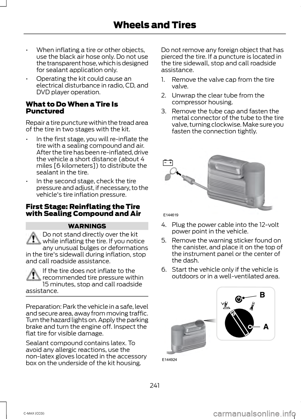
1. Remove the valve cap from the tire
valve.
2. Unwrap the clear tube from the compressor housing.
3. Remove the tube cap and fasten the metal connector of the tube to the tire
valve, turning clockwise. Make sure you
fasten the connection tightly. 4. Plug the power cable into the 12-volt
power point in the vehicle.
5. Remove the warning sticker found on the canister, and place it on the top of
the instrument panel or the center of
the dash.
6. Start the vehicle only if the vehicle is outdoors or in a well-ventilated area. 241
C-MAX (CCG) Wheels and TiresE144619 E144924
Page 247 of 447
TIRE CARE
Information About Uniform
Tire Quality Grading
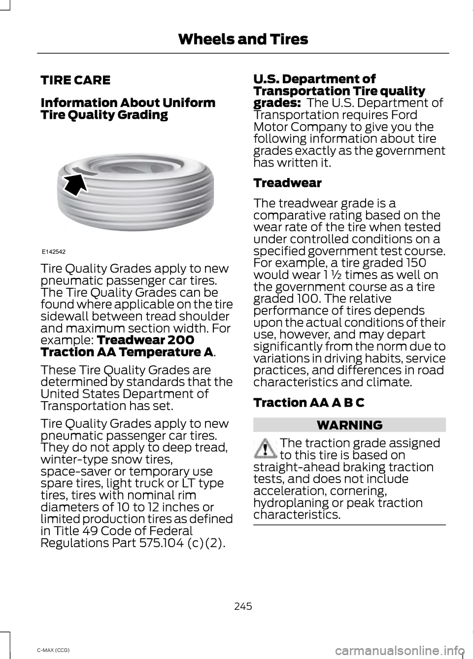
Tire Quality Grades apply to new
pneumatic passenger car tires.
The Tire Quality Grades can be
found where applicable on the tire
sidewall between tread shoulder
and maximum section width. For
example: Treadwear 200
Traction AA Temperature A.
These Tire Quality Grades are
determined by standards that the
United States Department of
Transportation has set.
Tire Quality Grades apply to new
pneumatic passenger car tires.
They do not apply to deep tread,
winter-type snow tires,
space-saver or temporary use
spare tires, light truck or LT type
tires, tires with nominal rim
diameters of 10 to 12 inches or
limited production tires as defined
in Title 49 Code of Federal
Regulations Part 575.104 (c)(2). U.S. Department of
Transportation Tire quality
grades:
The U.S. Department of
Transportation requires Ford
Motor Company to give you the
following information about tire
grades exactly as the government
has written it.
Treadwear
The treadwear grade is a
comparative rating based on the
wear rate of the tire when tested
under controlled conditions on a
specified government test course.
For example, a tire graded 150
would wear 1 ½ times as well on
the government course as a tire
graded 100. The relative
performance of tires depends
upon the actual conditions of their
use, however, and may depart
significantly from the norm due to
variations in driving habits, service
practices, and differences in road
characteristics and climate.
Traction AA A B C WARNING
The traction grade assigned
to this tire is based on
straight-ahead braking traction
tests, and does not include
acceleration, cornering,
hydroplaning or peak traction
characteristics. 245
C-MAX (CCG) Wheels and TiresE142542
Page 252 of 447
*Traction: The traction grades,
from highest to lowest are AA, A,
B, and C. The grades represent the
tire's ability to stop on wet
pavement as measured under
controlled conditions on specified
government test surfaces of
asphalt and concrete. A tire
marked C may have poor traction
performance.
*
Temperature: The temperature
grades are A (the highest), B and
C, representing the tire's
resistance to the generation of
heat and its ability to dissipate
heat when tested under controlled
conditions on a specified indoor
laboratory test wheel.
M. Maximum Inflation
Pressure:
Indicates the tire
manufacturer's maximum
permissible pressure, or the
pressure at which the maximum
load can be carried by the tire. This
pressure is normally higher than
the vehicle manufacturer's
recommended cold inflation
pressure, which can be found on
the Safety Compliance
Certification Label (affixed to
either the door hinge pillar,
door-latch post, or the door edge
that meets the door-latch post,
next to the driver's seating
position), or Tire Label which is
located on the B-Pillar or the edge
of the driver ’s door. The cold
inflation pressure should never be
set lower than the recommended
pressure on the vehicle label. The tire suppliers may have
additional markings, notes or
warnings such as standard load
or radial tubeless.
Additional Information
Contained on the Tire Sidewall
for LT Type Tires
Note:
Tire Quality Grades do not
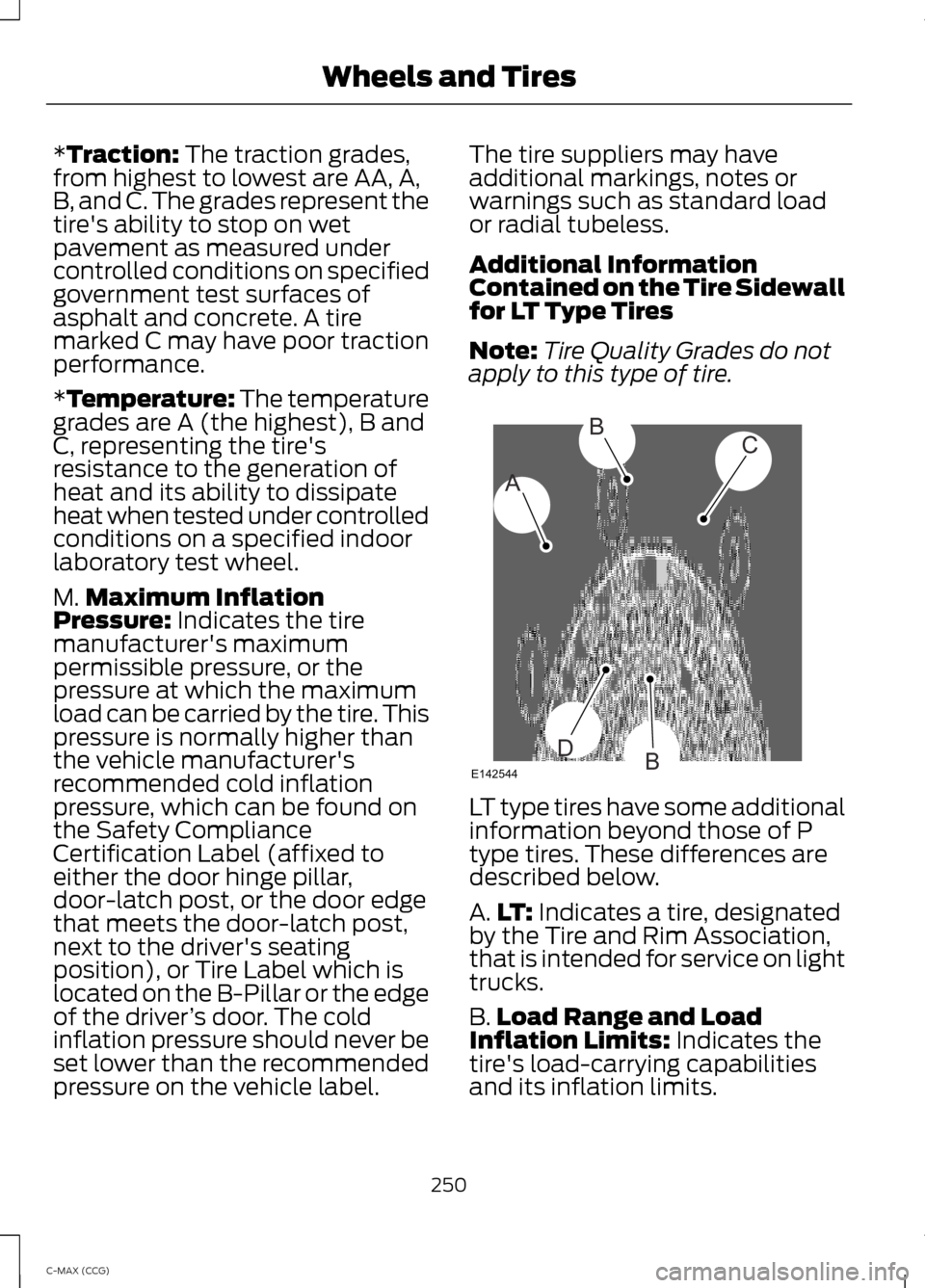
apply to this type of tire. LT type tires have some additional
information beyond those of P
type tires. These differences are
described below.
A.
LT:
Indicates a tire, designated
by the Tire and Rim Association,
that is intended for service on light
trucks.
B. Load Range and Load
Inflation Limits:
Indicates the
tire's load-carrying capabilities
and its inflation limits.
250
C-MAX (CCG) Wheels and TiresA
BC
BDE142544