lock FORD C MAX HYBRID 2014 2.G Repair Manual
[x] Cancel search | Manufacturer: FORD, Model Year: 2014, Model line: C MAX HYBRID, Model: FORD C MAX HYBRID 2014 2.GPages: 447, PDF Size: 8.06 MB
Page 221 of 447
presets, are also maintained in memory by
power from the low voltage battery. When
a technician disconnects and connects the
low voltage battery, these settings are
erased. Complete the following procedure
in order to restore the settings:
1. With the vehicle at a complete stop,
set the parking brake.
2. Shift the transmission into P.
3. Turn off all accessories.
4. Step on the brake pedal and start the vehicle.
5. Run the engine until it reaches normal operating temperature. While the
engine is warming up, complete the
following: Reset the clock. See Audio
System (page 272). Reset the power
windows bounce-back feature. See
Windows and Mirrors
(page 76).
Reset the radio station presets. See
Audio System
(page 272).
6. Allow the engine to idle for at least one
minute. If the engine turns off, step on
the accelerator to start the engine.
7. While the engine is running, step on the
brake pedal and shift the transmission
to N.
8. Allow the engine to run for at least one
minute by pressing on the accelerator
pedal.
9. Drive the vehicle at least 10 miles (16 kilometers) to completely relearn the
idle and fuel trim strategy.
Note: If you do not allow the engine to
relearn the idle and fuel trim strategy, the
idle quality of your vehicle may be adversely
affected until the engine computer
eventually relearns the idle trim and fuel
trim strategy. Note:
Always dispose of automotive
batteries in a responsible manner. Follow
your local authorized standards for disposal.
Call your local authorized recycling center
to find out more about recycling automotive
batteries.
Note: It is recommended that the negative
battery cable terminal be disconnected from
the battery if you plan to store your vehicle
for an extended period of time.
CHECKING THE WIPER
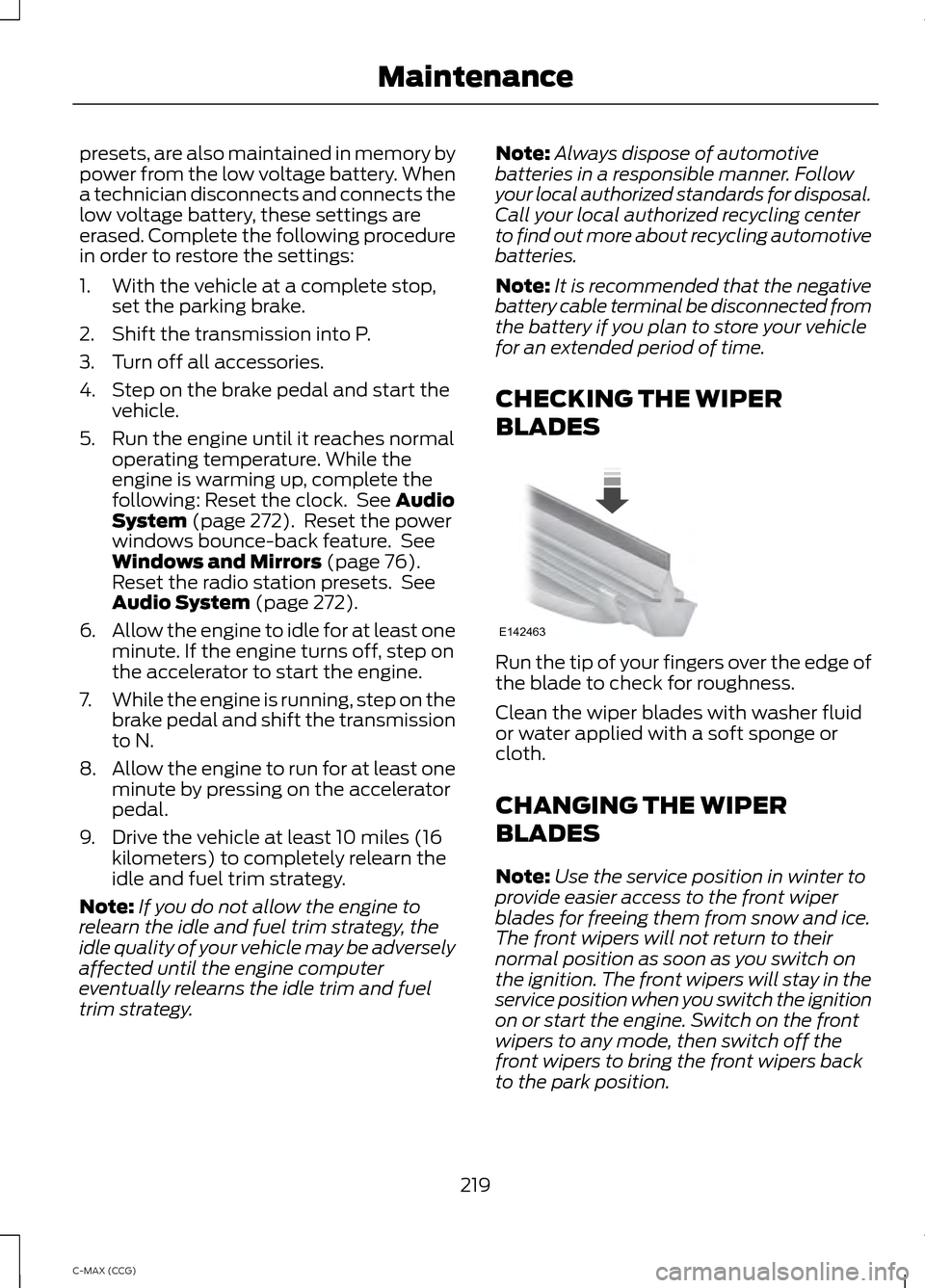
BLADES Run the tip of your fingers over the edge of
the blade to check for roughness.
Clean the wiper blades with washer fluid
or water applied with a soft sponge or
cloth.
CHANGING THE WIPER
BLADES
Note:
Use the service position in winter to
provide easier access to the front wiper
blades for freeing them from snow and ice.
The front wipers will not return to their
normal position as soon as you switch on
the ignition. The front wipers will stay in the
service position when you switch the ignition
on or start the engine. Switch on the front
wipers to any mode, then switch off the
front wipers to bring the front wipers back
to the park position.
219
C-MAX (CCG) MaintenanceE142463
Page 222 of 447
Note:
The windshield wiper blades are
different in length. If you install wiper blades
of the wrong length, the wipers may not
work correctly. If equipped with autowipers,
the rain sensor may not work correctly.
Note: Make sure that the wiper blade locks
into place. Lower the wiper arm and blade
back to the windshield. The wiper arms will
automatically return to their normal position
when the ignition is turned on.
Note: Replace wiper blades at least once
per year for optimum performance.
Note: Poor wiper quality can be improved
by cleaning the wiper blades and the
windshield
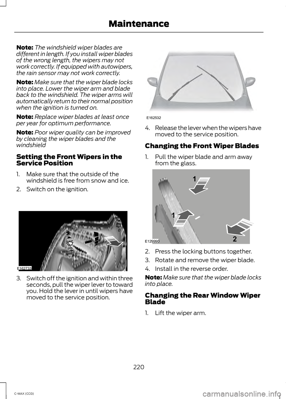
Setting the Front Wipers in the
Service Position
1. Make sure that the outside of the windshield is free from snow and ice.
2. Switch on the ignition. 3.
Switch off the ignition and within three
seconds, pull the wiper lever to toward
you. Hold the lever in until wipers have
moved to the service position. 4.
Release the lever when the wipers have
moved to the service position.
Changing the Front Wiper Blades
1. Pull the wiper blade and arm away from the glass. 2. Press the locking buttons together.
3. Rotate and remove the wiper blade.
4. Install in the reverse order.
Note:
Make sure that the wiper blade locks
into place.
Changing the Rear Window Wiper
Blade
1. Lift the wiper arm.
220
C-MAX (CCG) MaintenanceE162733 E162532 E129990
1
1 2
Page 223 of 447
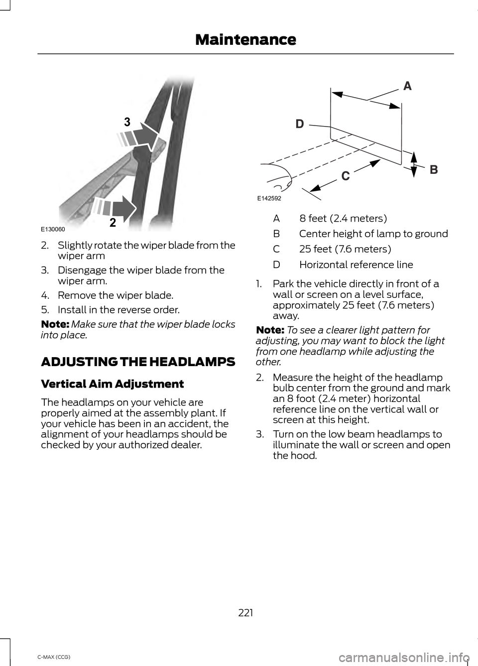
2.
Slightly rotate the wiper blade from the
wiper arm
3. Disengage the wiper blade from the wiper arm.
4. Remove the wiper blade.
5. Install in the reverse order.
Note: Make sure that the wiper blade locks
into place.
ADJUSTING THE HEADLAMPS
Vertical Aim Adjustment
The headlamps on your vehicle are
properly aimed at the assembly plant. If
your vehicle has been in an accident, the
alignment of your headlamps should be
checked by your authorized dealer. 8 feet (2.4 meters)
A
Center height of lamp to ground
B
25 feet (7.6 meters)
C
Horizontal reference line
D
1. Park the vehicle directly in front of a wall or screen on a level surface,
approximately 25 feet (7.6 meters)
away.
Note: To see a clearer light pattern for
adjusting, you may want to block the light
from one headlamp while adjusting the
other.
2. Measure the height of the headlamp bulb center from the ground and mark
an 8 foot (2.4 meter) horizontal
reference line on the vertical wall or
screen at this height.
3. Turn on the low beam headlamps to illuminate the wall or screen and open
the hood.
221
C-MAX (CCG) MaintenanceE130060
3
2 E142592
Page 224 of 447
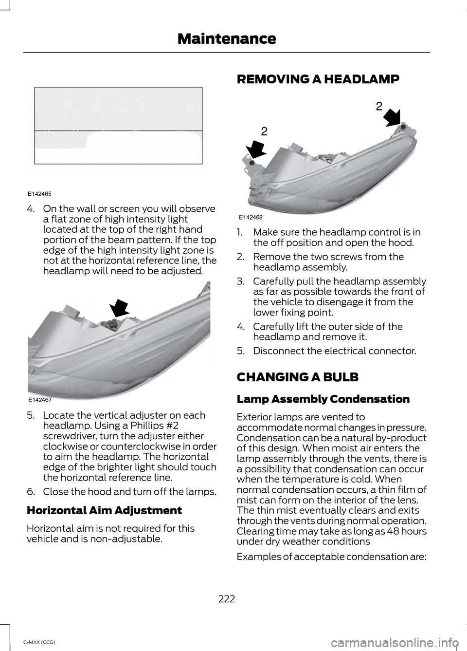
4. On the wall or screen you will observe
a flat zone of high intensity light
located at the top of the right hand
portion of the beam pattern. If the top
edge of the high intensity light zone is
not at the horizontal reference line, the
headlamp will need to be adjusted. 5. Locate the vertical adjuster on each
headlamp. Using a Phillips #2
screwdriver, turn the adjuster either
clockwise or counterclockwise in order
to aim the headlamp. The horizontal
edge of the brighter light should touch
the horizontal reference line.
6. Close the hood and turn off the lamps.
Horizontal Aim Adjustment
Horizontal aim is not required for this
vehicle and is non-adjustable. REMOVING A HEADLAMP
1. Make sure the headlamp control is in
the off position and open the hood.
2. Remove the two screws from the headlamp assembly.
3. Carefully pull the headlamp assembly as far as possible towards the front of
the vehicle to disengage it from the
lower fixing point.
4. Carefully lift the outer side of the headlamp and remove it.
5. Disconnect the electrical connector.
CHANGING A BULB
Lamp Assembly Condensation
Exterior lamps are vented to
accommodate normal changes in pressure.
Condensation can be a natural by-product
of this design. When moist air enters the
lamp assembly through the vents, there is
a possibility that condensation can occur
when the temperature is cold. When
normal condensation occurs, a thin film of
mist can form on the interior of the lens.
The thin mist eventually clears and exits
through the vents during normal operation.
Clearing time may take as long as 48 hours
under dry weather conditions
Examples of acceptable condensation are:
222
C-MAX (CCG) MaintenanceE142465 E142467 2
2
E142468
Page 225 of 447
•
Presence of thin mist (no streaks, drip
marks or droplets).
• Fine mist covers less than 50% of the
lens.
Examples of unacceptable moisture
(usually caused by a lamp water leak) are:
• Water puddle inside the lamp.
• Large water droplets, drip marks or
streaks present on the interior of the
lens.
Take your vehicle to a dealer for service if
any of the above conditions of
unacceptable moisture are present.
Replacing Headlamp Bulbs WARNING
Handle a halogen headlamp bulb
carefully and keep out of children
’s
reach. Grasp the bulb by only its
plastic base and do not touch the glass.
The oil from your hand could cause the
bulb to break the next time the headlamps
are operated. Note:
If the bulb is accidentally touched, it
should be cleaned with rubbing alcohol
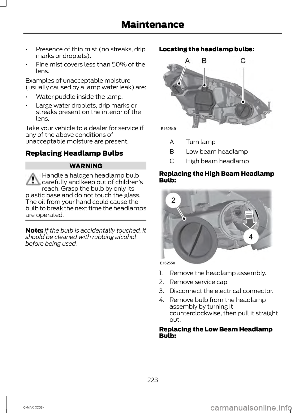
before being used. Locating the headlamp bulbs: Turn lamp
A
Low beam headlamp
B
High beam headlamp
C
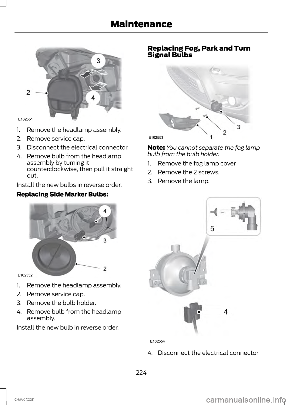
Replacing the High Beam Headlamp
Bulb: 1. Remove the headlamp assembly.
2. Remove service cap.
3. Disconnect the electrical connector.
4. Remove bulb from the headlamp
assembly by turning it
counterclockwise, then pull it straight
out.
Replacing the Low Beam Headlamp
Bulb:
223
C-MAX (CCG) MaintenanceE162549 E162550
Page 226 of 447
1. Remove the headlamp assembly.
2. Remove service cap.
3. Disconnect the electrical connector.
4. Remove bulb from the headlamp
assembly by turning it
counterclockwise, then pull it straight
out.
Install the new bulbs in reverse order.
Replacing Side Marker Bulbs: 1. Remove the headlamp assembly.
2. Remove service cap.
3. Remove the bulb holder.
4. Remove bulb from the headlamp
assembly.
Install the new bulb in reverse order. Replacing Fog, Park and Turn
Signal Bulbs
Note:
You cannot separate the fog lamp
bulb from the bulb holder.
1. Remove the fog lamp cover
2. Remove the 2 screws.
3. Remove the lamp. 4. Disconnect the electrical connector
224
C-MAX (CCG) MaintenanceE162551 E162552 E162553 4
5
E162554
Page 227 of 447
5.
Turn the bulb holder counterclockwise
and remove it.
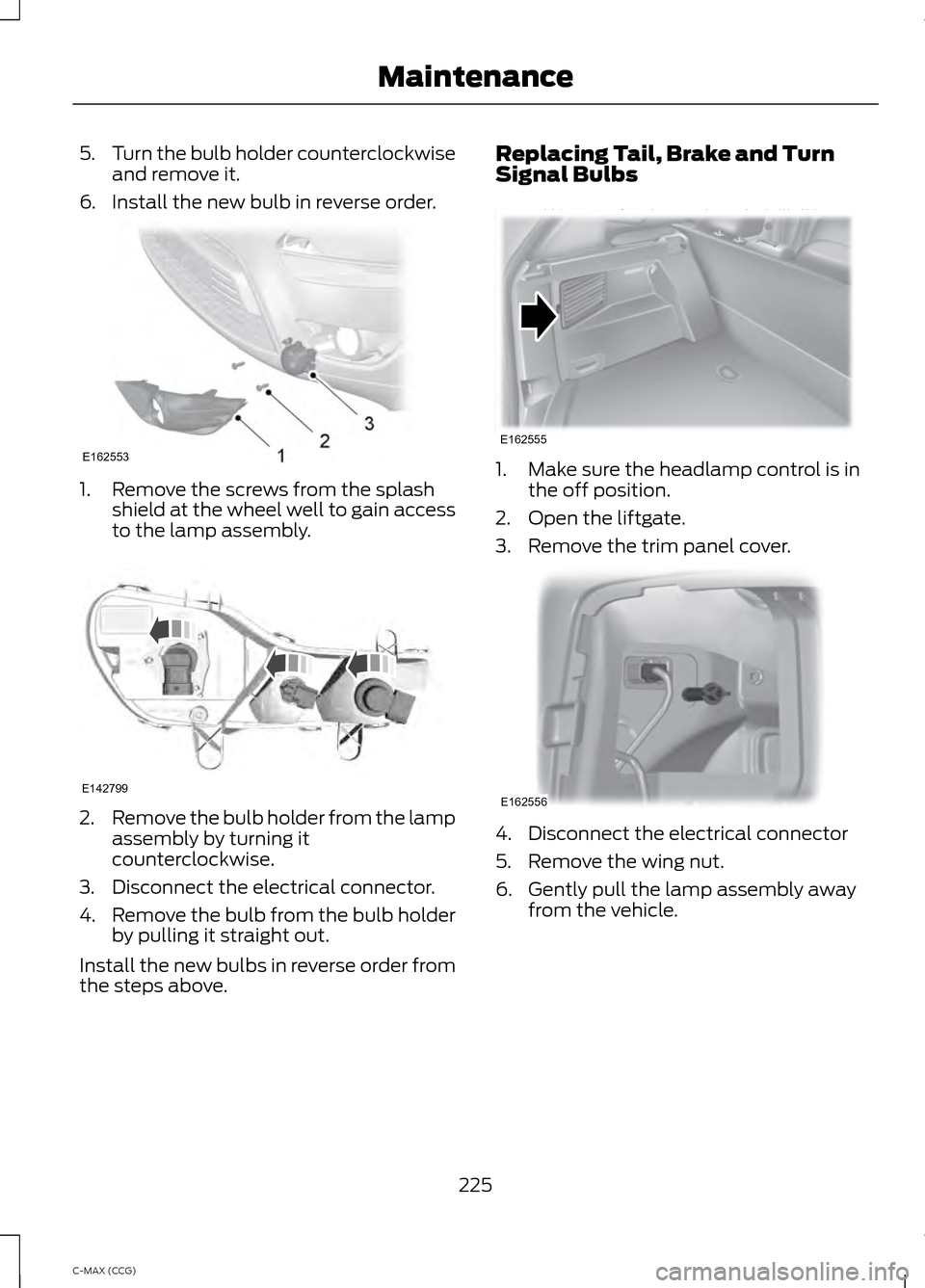
6. Install the new bulb in reverse order. 1. Remove the screws from the splash
shield at the wheel well to gain access
to the lamp assembly. 2.
Remove the bulb holder from the lamp
assembly by turning it
counterclockwise.
3. Disconnect the electrical connector.
4. Remove the bulb from the bulb holder
by pulling it straight out.
Install the new bulbs in reverse order from
the steps above. Replacing Tail, Brake and Turn
Signal Bulbs
1. Make sure the headlamp control is in
the off position.
2. Open the liftgate.
3. Remove the trim panel cover. 4. Disconnect the electrical connector
5. Remove the wing nut.
6. Gently pull the lamp assembly away
from the vehicle.
225
C-MAX (CCG) MaintenanceE162553 E142799 E162555 E162556
Page 228 of 447
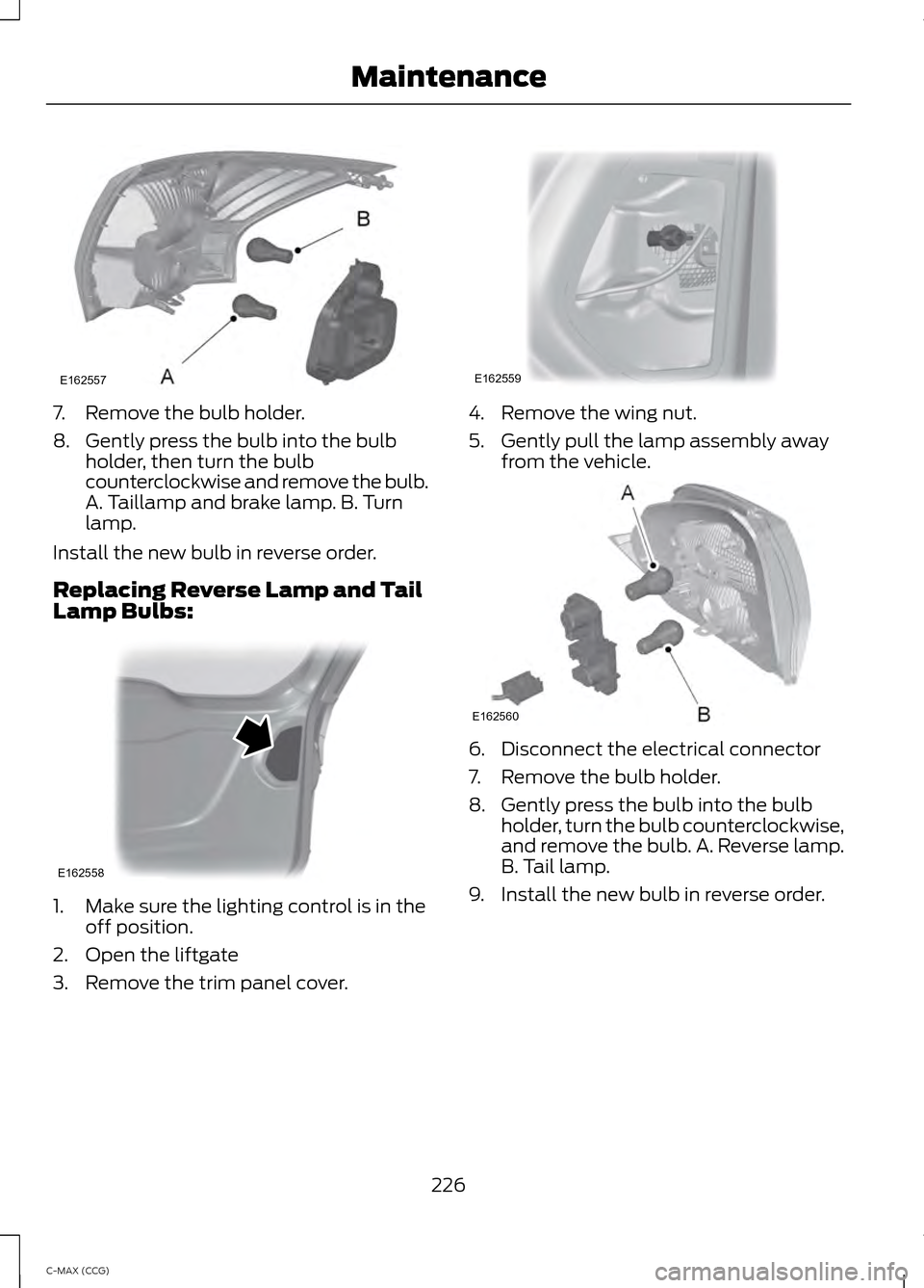
7. Remove the bulb holder.
8. Gently press the bulb into the bulb
holder, then turn the bulb
counterclockwise and remove the bulb.
A. Taillamp and brake lamp. B. Turn
lamp.
Install the new bulb in reverse order.
Replacing Reverse Lamp and Tail
Lamp Bulbs: 1. Make sure the lighting control is in the
off position.
2. Open the liftgate
3. Remove the trim panel cover. 4. Remove the wing nut.
5. Gently pull the lamp assembly away
from the vehicle. 6. Disconnect the electrical connector
7. Remove the bulb holder.
8. Gently press the bulb into the bulb
holder, turn the bulb counterclockwise,
and remove the bulb. A. Reverse lamp.
B. Tail lamp.
9. Install the new bulb in reverse order.
226
C-MAX (CCG) MaintenanceE162557 E162558 E162559 E162560
Page 235 of 447
•
Wash your vehicle first, using cool or
lukewarm water and a neutral pH
shampoo, such as Motorcraft Detail
Wash.
• Use Motorcraft Custom Bright Metal
Cleaner. Apply the product as you
would a wax to clean bumpers and
other chrome parts; allow the cleaner
to dry for a few minutes, then wipe off
the haze with a clean, dry rag.
• Do not apply cleaning product to hot
surfaces and do not leave cleaning
product on chrome surfaces longer
than the time recommended.
• Using other non-recommended
cleaners can result in severe and
permanent cosmetic damage.
Underbody
Flush the complete underside of your
vehicle frequently. Keep body and door
drain holes free from packed dirt.
Cleaning Plastic Exterior Parts
Use only approved products to clean
plastic parts
• For routine cleaning, use Motorcraft
Detail Wash.
• If tar or grease spots are present, use
Motorcraft Bug and Tar Remover.
WAXING
Regular waxing is necessary to protect your
car's paint from the elements. We
recommend that you wash and wax the
painted surface once or twice a year.
When washing and waxing, park your
vehicle in a shaded area out of direct
sunlight. Always wash your vehicle before
applying wax. •
Use a quality wax that does not contain
abrasives.
• Follow the manufacturer ’s instructions
to apply and remove the wax.
• Apply a small amount of wax in a
back-and-forth motion, not in circles.
• Do not allow wax to come in contact
with any non-body (low-gloss black)
colored trim. The wax will discolor or
stain the parts over time.
•Roof racks.
• Bumpers.
• Grained door handles.
• Side moldings.
• Mirror housings.
• Windshield cowl area.
• Do not apply wax to glass areas.
• After waxing, your car's paint should
feel smooth, and be free of streaks and
smudges.
CLEANING THE ENGINE
Engines are more efficient when they are
clean because grease and dirt buildup keep
the engine warmer than normal.
When washing:
• Take care when using a power washer
to clean the engine. The high-pressure
fluid could penetrate the sealed parts
and cause damage.
• Do not spray a hot engine with cold
water to avoid cracking the engine
block or other engine components.
• Spray Motorcraft Engine Shampoo and
Degreaser on all parts that require
cleaning and pressure rinse clean. In
Canada, use Motorcraft Engine
Shampoo.
• Never wash or rinse the engine while it
is hot or running; water in the running
engine may cause internal damage.
233
C-MAX (CCG) Vehicle Care
Page 243 of 447
•
When inflating a tire or other objects,
use the black air hose only. Do not use
the transparent hose, which is designed
for sealant application only.
• Operating the kit could cause an
electrical disturbance in radio, CD, and
DVD player operation.
What to Do When a Tire Is
Punctured
Repair a tire puncture within the tread area
of the tire in two stages with the kit.
• In the first stage, you will re-inflate the
tire with a sealing compound and air.
After the tire has been re-inflated, drive
the vehicle a short distance (about 4
miles [6 kilometers]) to distribute the
sealant in the tire.
• In the second stage, check the tire
pressure and adjust, if necessary, to the
vehicle's tire inflation pressure.
First Stage: Reinflating the Tire
with Sealing Compound and Air WARNINGS
Do not stand directly over the kit
while inflating the tire. If you notice
any unusual bulges or deformations
in the tire's sidewall during inflation, stop
and call roadside assistance. If the tire does not inflate to the
recommended tire pressure within
15 minutes, stop and call roadside
assistance. Preparation: Park the vehicle in a safe, level
and secure area, away from moving traffic.
Turn the hazard lights on. Apply the parking
brake and turn the engine off. Inspect the
flat tire for visible damage.
Sealant compound contains latex. To
avoid any allergic reactions, use the
non-latex gloves located in the accessory
box on the underside of the kit housing. Do not remove any foreign object that has
pierced the tire. If a puncture is located in
the tire sidewall, stop and call roadside
assistance.
1. Remove the valve cap from the tire
valve.
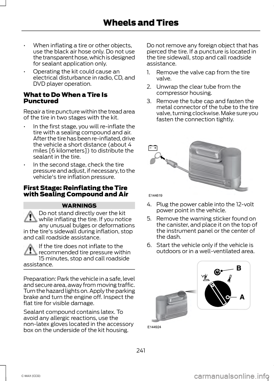
2. Unwrap the clear tube from the compressor housing.
3. Remove the tube cap and fasten the metal connector of the tube to the tire
valve, turning clockwise. Make sure you
fasten the connection tightly. 4. Plug the power cable into the 12-volt
power point in the vehicle.
5. Remove the warning sticker found on the canister, and place it on the top of
the instrument panel or the center of
the dash.
6. Start the vehicle only if the vehicle is outdoors or in a well-ventilated area. 241
C-MAX (CCG) Wheels and TiresE144619 E144924