engine FORD E-250 2005 Service Manual
[x] Cancel search | Manufacturer: FORD, Model Year: 2005, Model line: E-250, Model: FORD E-250 2005Pages: 248, PDF Size: 2.55 MB
Page 161 of 248
If your vehicle goes off the edge of the pavement
•If your vehicle goes off the edge of the pavement, slow down, but
avoid severe brake application, ease the vehicle back onto the
pavement only after reducing your speed. Do not turn the steering
wheel too sharply while returning to the road surface.
•It may be safer to stay on the apron or shoulder of the road and slow
down gradually before returning to the pavement. You may lose
control if you do not slow down or if you turn the steering wheel too
sharply or abruptly.
•It often may be less risky to strike small objects, such as highway
reflectors, with minor damage to your vehicle rather than attempt a
sudden return to the pavement which could cause the vehicle to slide
sideways out of control or roll over. Remember, your safety and the
safety of others should be your primary concern.
Vehicles with a higher center of gravity such as utility and
four-wheel drive vehicles handle differently than vehicles with a
lower center of gravity. Utility and four-wheel drive vehicles arenot
designed for cornering at speeds as high as passenger cars any more
than low-slung sports cars are designed to perform satisfactorily under
off-road conditions. Avoid sharp turns, excessive speed and abrupt
maneuvers in these vehicles. Failure to drive cautiously could result in
an increased risk of loss of vehicle control, vehicle rollover, personal
injury and death.
VEHICLE USED AS A STATIONARY POWER SOURCE
Auxiliary equipment called power take-off, or PTO, is often added to the
engine or transmission to operate utility equipment. Examples include
wheel-lift for tow trucks, tools for construction, and cranes. PTO
applications draw auxiliary horsepower from the powertrain, often while
the vehicle is stationary. In this condition there is limited cooling air flow
through the radiator and around the vehicle that normally occurs when a
vehicle is moving. Depending on the level and duration of auxiliary
horsepower draw, vehicle and surrounding environmental conditions, and
other factors, this can contribute to elevated transmission fluid
temperatures and resultant accelerated fluid deterioration, fuel vapor
over-pressurization, and other concerns. Ford trucks are fully qualified
for stationary PTO operation for 10 minutes or less of continuous
operation. For extended duration stationary PTO operation (beyond 10
minutes) diesel engine is recommended, and further consult your
aftermarket PTO installer.
2005 Econoline(eco)
Owners Guide (post-2002-fmt)
USA(fus)
Driving
161
ProCarManuals.com
Page 162 of 248
A more complete description of PTO operation is discussed in the Ford
Truck Body Builders Layout Book, found at
www.fleet.ford.com/truckbbas.
DRIVING THROUGH WATER
If driving through deep or standing water is unavoidable, proceed very
slowly especially when the depth is not known. Never drive through
water that is higher than the bottom of the hubs (for trucks) or the
bottom of the wheel rims (for cars). When driving through water,
traction or brake capability may be limited. Also, water may enter your
engine’s air intake and severely damage your engine or your vehicle may
stall.Driving through deep water where the transmission vent
tube is submerged may allow water into the transmission and
cause internal transmission damage.
Once through the water, always dry the brakes by moving your
vehicle slowly while applying light pressure on the brake pedal.
Wet brakes do not stop the vehicle as quickly as dry brakes.
2005 Econoline(eco)
Owners Guide (post-2002-fmt)
USA(fus)
Driving
162
ProCarManuals.com
Page 164 of 248
Canadian customers who require roadside assistance, call
1–800–665–2006.
Motorhome customers in the U.S and Canada should contact
1–800–444–3311.
If you need to arrange roadside assistance for yourself, Ford Motor
Company will reimburse a reasonable amount. To obtain reimbursement
information, U.S. Ford or Mercury vehicles customers call
1-800-241-3673; Lincoln vehicle customers call 1–800–521–4140.
Canadian customers who need to obtain reimbursement information, call
1–800–665–2006.
ROADSIDE COVERAGE BEYOND BASIC WARRANTY
In the United States, you may purchase additional roadside assistance
coverage beyond this period through the Ford Auto Club by contacting
your Ford or Lincoln Mercury dealer.
Similarly in Canada, for uninterrupted Roadside Assistance coverage, you
may purchase extended coverage prior to your Basic Warranty’s Roadside
Assistance expiring. For more information and enrollment, contact
1–877–294–2582 or visit our website at www.ford.ca.
HAZARD FLASHER
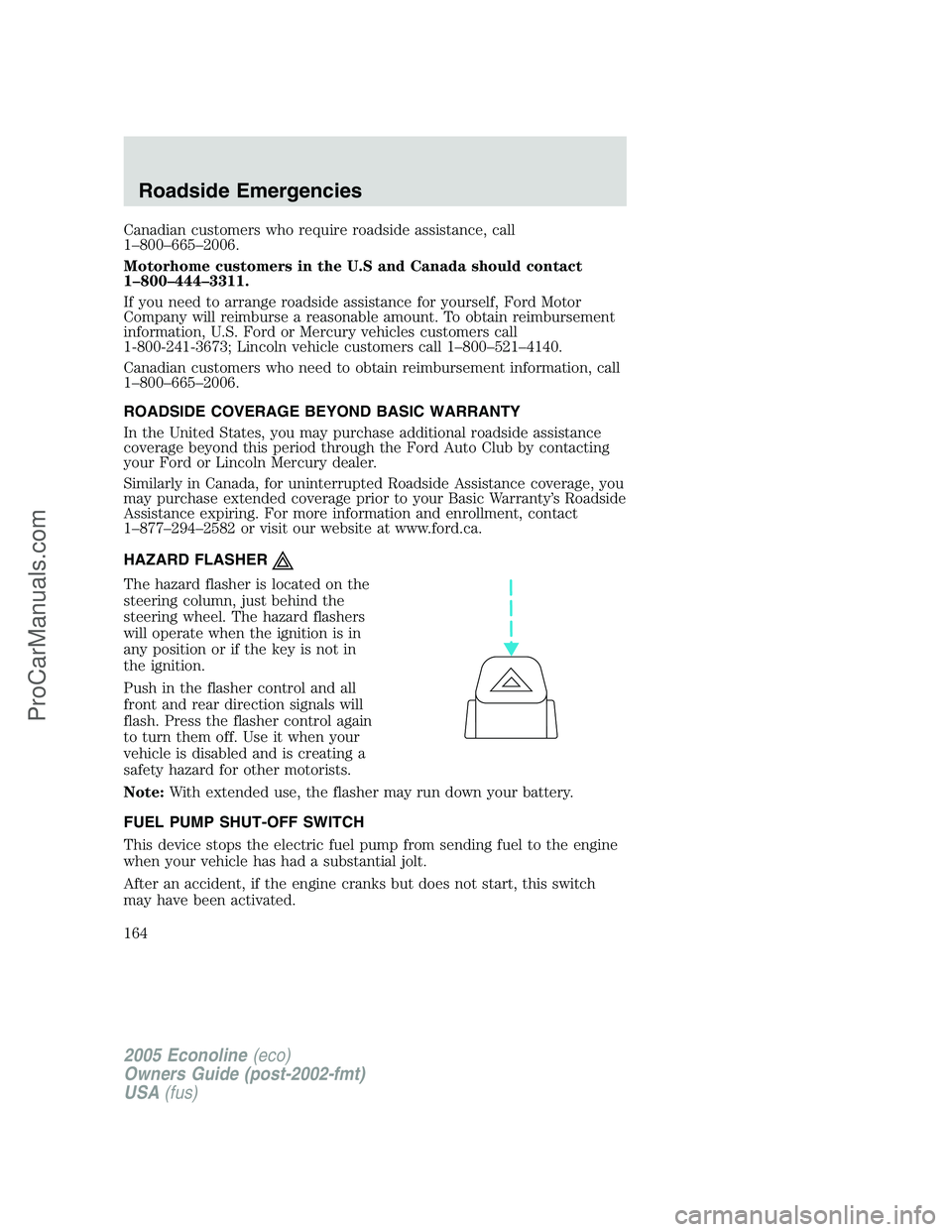
The hazard flasher is located on the
steering column, just behind the
steering wheel. The hazard flashers
will operate when the ignition is in
any position or if the key is not in
the ignition.
Push in the flasher control and all
front and rear direction signals will
flash. Press the flasher control again
to turn them off. Use it when your
vehicle is disabled and is creating a
safety hazard for other motorists.
Note:With extended use, the flasher may run down your battery.
FUEL PUMP SHUT-OFF SWITCH
This device stops the electric fuel pump from sending fuel to the engine
when your vehicle has had a substantial jolt.
After an accident, if the engine cranks but does not start, this switch
may have been activated.
2005 Econoline(eco)
Owners Guide (post-2002-fmt)
USA(fus)
Roadside Emergencies
164
ProCarManuals.com
Page 169 of 248
Fuse/Relay
LocationFuse Amp
RatingPassenger Compartment Fuse Panel
Description
9 5A Wiper control module
10 20A Main light switch, Park lamps, License
lamp (external lamps), Multi-function
switch (flash-to-pass)
11 15A Multi-function switch (hazards), Brake
lamp switch, Brake lamps
12 15A Back-up lamps, Auxiliary battery relay
(gasoline engine only), Trailer tow relay
13 15A Blend door actuator, Function selector
switch
14 5A Instrument cluster
15 5A Trailer battery charge relay, Cluster
16 30A Power seats
17 5A Power mirrors
18 — Not used
19 — Not used
20 10A Restraints
21 — Not used
22 15A Memory power radio, Battery saver relay,
Instrument cluster, Courtesy lamp relay,
Accessory delay relay
23 20A Power locks w/RKE
24 — Not used
25 10A Left headlamp (low beam)
26 20A Cigar lighter, Diagnostics
27 5A Radio
28 — Not used
29 — Not used
30 15A Headlamps (high beam indicator)
31 10A Right headlamp (low beam)
32 20A Power point #1 (instrument panel)
33 10A Start relay
2005 Econoline(eco)
Owners Guide (post-2002-fmt)
USA(fus)
Roadside Emergencies
169
ProCarManuals.com
Page 170 of 248
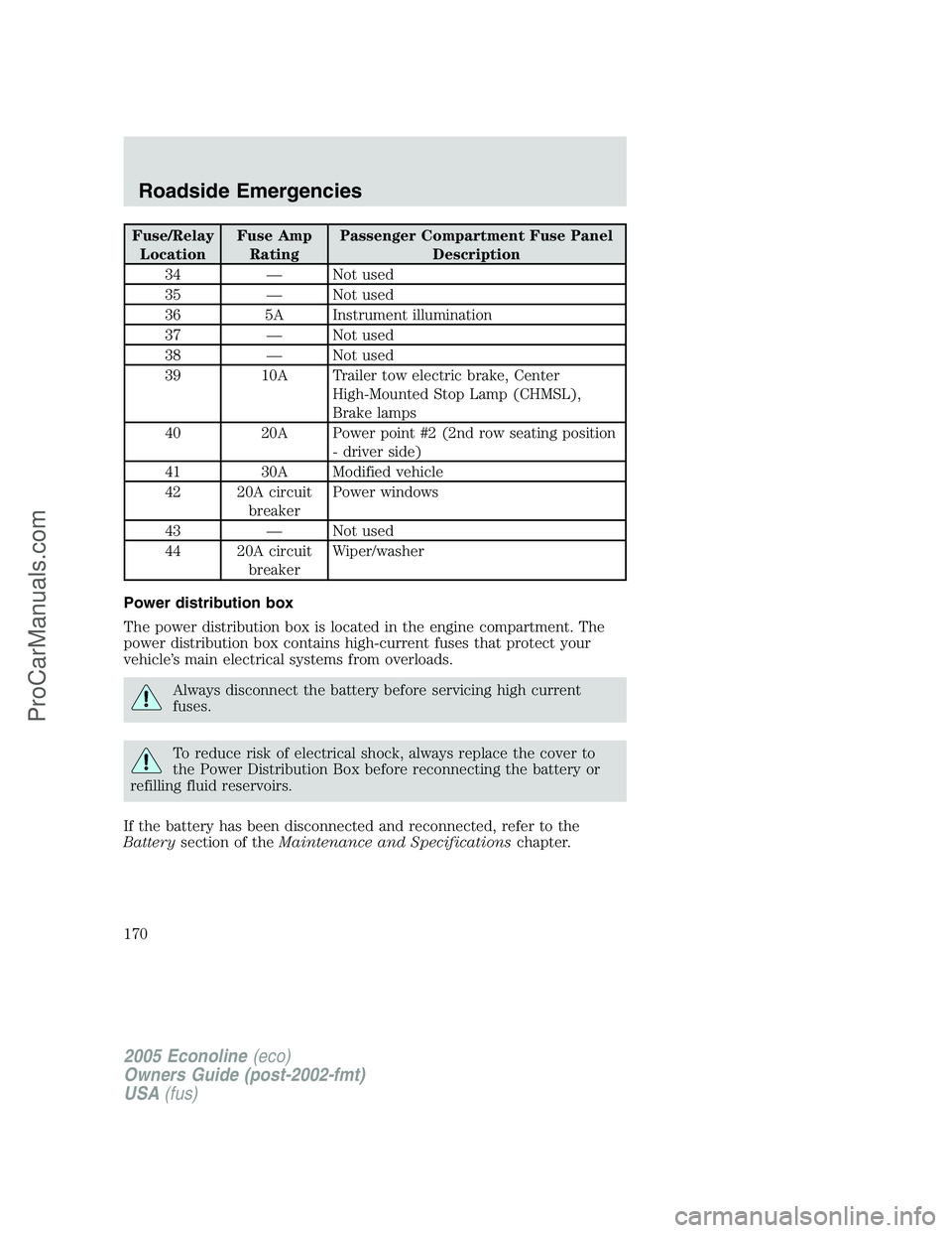
Fuse/Relay
LocationFuse Amp
RatingPassenger Compartment Fuse Panel
Description
34 — Not used
35 — Not used
36 5A Instrument illumination
37 — Not used
38 — Not used
39 10A Trailer tow electric brake, Center
High-Mounted Stop Lamp (CHMSL),
Brake lamps
40 20A Power point #2 (2nd row seating position
- driver side)
41 30A Modified vehicle
42 20A circuit
breakerPower windows
43 — Not used
44 20A circuit
breakerWiper/washer
Power distribution box
The power distribution box is located in the engine compartment. The
power distribution box contains high-current fuses that protect your
vehicle’s main electrical systems from overloads.
Always disconnect the battery before servicing high current
fuses.
To reduce risk of electrical shock, always replace the cover to
the Power Distribution Box before reconnecting the battery or
refilling fluid reservoirs.
If the battery has been disconnected and reconnected, refer to the
Batterysection of theMaintenance and Specificationschapter.
2005 Econoline(eco)
Owners Guide (post-2002-fmt)
USA(fus)
Roadside Emergencies
170
ProCarManuals.com
Page 172 of 248
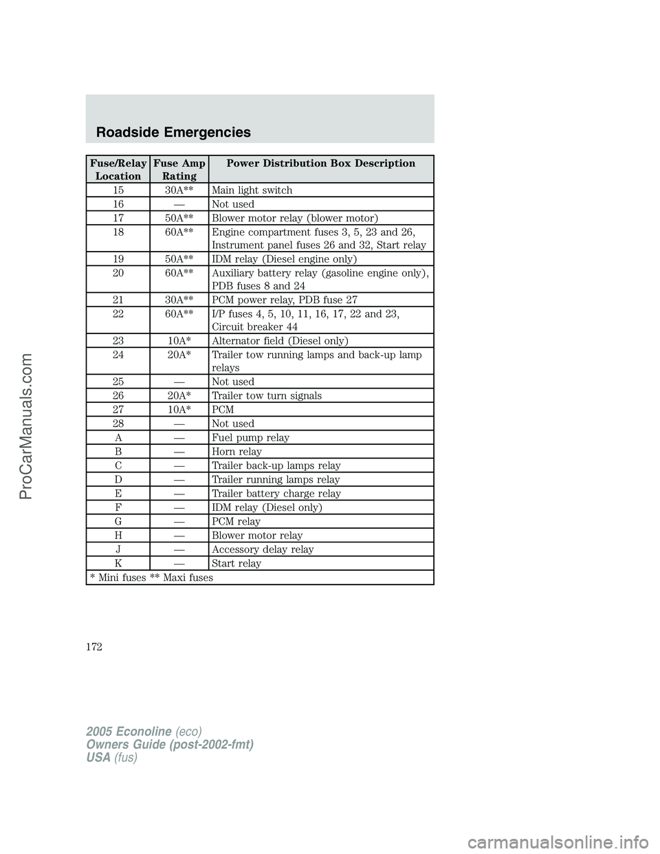
Fuse/Relay
LocationFuse Amp
RatingPower Distribution Box Description
15 30A** Main light switch
16 — Not used
17 50A** Blower motor relay (blower motor)
18 60A** Engine compartment fuses 3, 5, 23 and 26,
Instrument panel fuses 26 and 32, Start relay
19 50A** IDM relay (Diesel engine only)
20 60A** Auxiliary battery relay (gasoline engine only),
PDB fuses 8 and 24
21 30A** PCM power relay, PDB fuse 27
22 60A** I/P fuses 4, 5, 10, 11, 16, 17, 22 and 23,
Circuit breaker 44
23 10A* Alternator field (Diesel only)
24 20A* Trailer tow running lamps and back-up lamp
relays
25 — Not used
26 20A* Trailer tow turn signals
27 10A* PCM
28 — Not used
A — Fuel pump relay
B — Horn relay
C — Trailer back-up lamps relay
D — Trailer running lamps relay
E — Trailer battery charge relay
F — IDM relay (Diesel only)
G — PCM relay
H — Blower motor relay
J — Accessory delay relay
K — Start relay
* Mini fuses ** Maxi fuses
2005 Econoline(eco)
Owners Guide (post-2002-fmt)
USA(fus)
Roadside Emergencies
172
ProCarManuals.com
Page 173 of 248
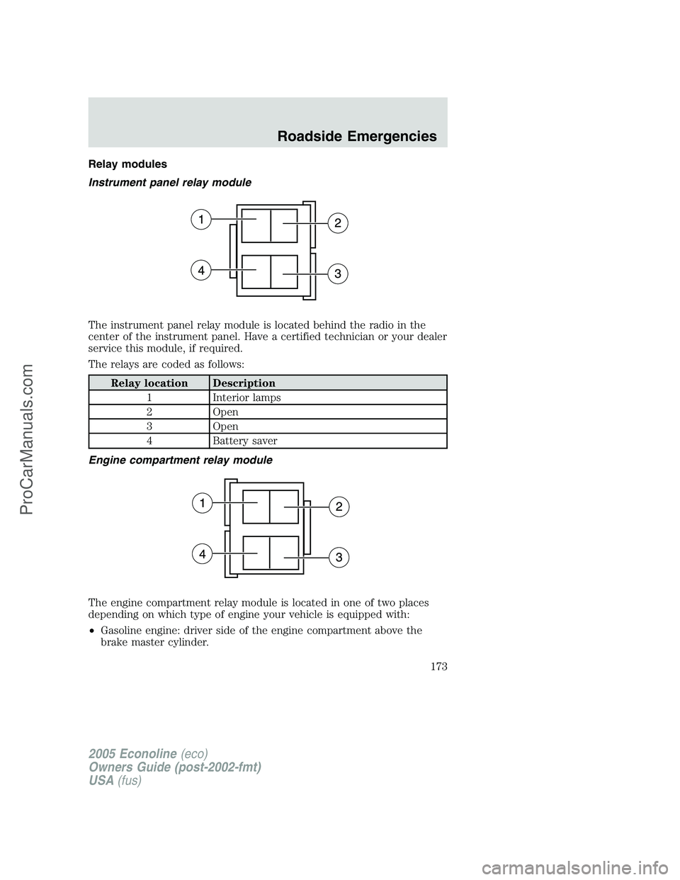
Relay modules
Instrument panel relay module
The instrument panel relay module is located behind the radio in the
center of the instrument panel. Have a certified technician or your dealer
service this module, if required.
The relays are coded as follows:
Relay location Description
1 Interior lamps
2 Open
3 Open
4 Battery saver
Engine compartment relay module
The engine compartment relay module is located in one of two places
depending on which type of engine your vehicle is equipped with:
•Gasoline engine: driver side of the engine compartment above the
brake master cylinder.
2005 Econoline(eco)
Owners Guide (post-2002-fmt)
USA(fus)
Roadside Emergencies
173
ProCarManuals.com
Page 174 of 248
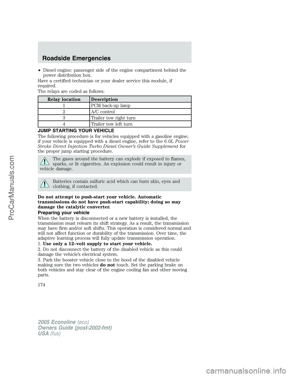
•Diesel engine: passenger side of the engine compartment behind the
power distribution box.
Have a certified technician or your dealer service this module, if
required.
The relays are coded as follows:
Relay location Description
1 PCM back-up lamp
2 A/C control
3 Trailer tow right turn
4 Trailer tow left turn
JUMP STARTING YOUR VEHICLE
The following procedure is for vehicles equipped with a gasoline engine;
if your vehicle is equipped with a diesel engine, refer to the6.0L Power
Stroke Direct Injection Turbo Diesel Owner’s Guide Supplementfor
the proper jump starting procedure.
The gases around the battery can explode if exposed to flames,
sparks, or lit cigarettes. An explosion could result in injury or
vehicle damage.
Batteries contain sulfuric acid which can burn skin, eyes and
clothing, if contacted.
Do not attempt to push-start your vehicle. Automatic
transmissions do not have push-start capability; doing so may
damage the catalytic converter.
Preparing your vehicle
When the battery is disconnected or a new battery is installed, the
transmission must relearn its shift strategy. As a result, the transmission
may have firm and/or soft shifts. This operation is considered normal and
will not affect function or durability of the transmission. Over time, the
adaptive learning process will fully update transmission operation.
1.Use only a 12–volt supply to start your vehicle.
2. Do not disconnect the battery of the disabled vehicle as this could
damage the vehicle’s electrical system.
3. Park the booster vehicle close to the hood of the disabled vehicle
making sure the two vehiclesdo nottouch. Set the parking brake on
both vehicles and stay clear of the engine cooling fan and other moving
parts.
2005 Econoline(eco)
Owners Guide (post-2002-fmt)
USA(fus)
Roadside Emergencies
174
ProCarManuals.com
Page 176 of 248
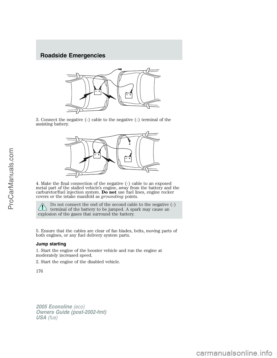
3. Connect the negative (-) cable to the negative (-) terminal of the
assisting battery.
4. Make the final connection of the negative (-) cable to an exposed
metal part of the stalled vehicle’s engine, away from the battery and the
carburetor/fuel injection system.Do notuse fuel lines, engine rocker
covers or the intake manifold asgroundingpoints.
Do not connect the end of the second cable to the negative (-)
terminal of the battery to be jumped. A spark may cause an
explosion of the gases that surround the battery.
5. Ensure that the cables are clear of fan blades, belts, moving parts of
both engines, or any fuel delivery system parts.
Jump starting
1. Start the engine of the booster vehicle and run the engine at
moderately increased speed.
2. Start the engine of the disabled vehicle.
+–+–
+–+–
2005 Econoline(eco)
Owners Guide (post-2002-fmt)
USA(fus)
Roadside Emergencies
176
ProCarManuals.com
Page 177 of 248
3. Once the disabled vehicle has been started, run both engines for an
additional three minutes before disconnecting the jumper cables.
Removing the jumper cables
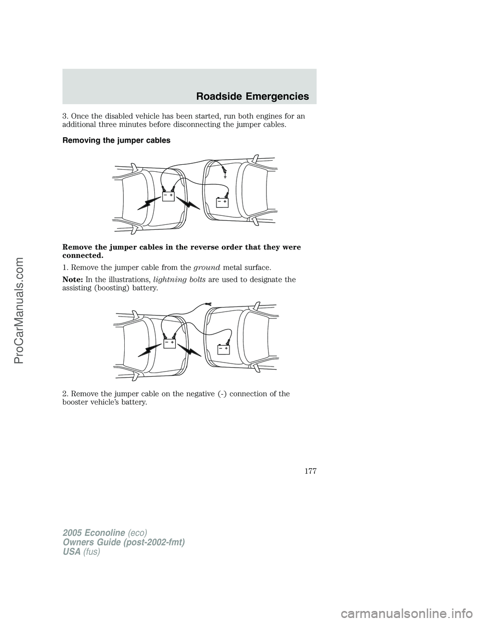
Remove the jumper cables in the reverse order that they were
connected.
1. Remove the jumper cable from thegroundmetal surface.
Note:In the illustrations,lightning boltsare used to designate the
assisting (boosting) battery.
2. Remove the jumper cable on the negative (-) connection of the
booster vehicle’s battery.
+–+–
+–+–
2005 Econoline(eco)
Owners Guide (post-2002-fmt)
USA(fus)
Roadside Emergencies
177
ProCarManuals.com