clock FORD E-250 2012 User Guide
[x] Cancel search | Manufacturer: FORD, Model Year: 2012, Model line: E-250, Model: FORD E-250 2012Pages: 335, PDF Size: 2.63 MB
Page 63 of 335
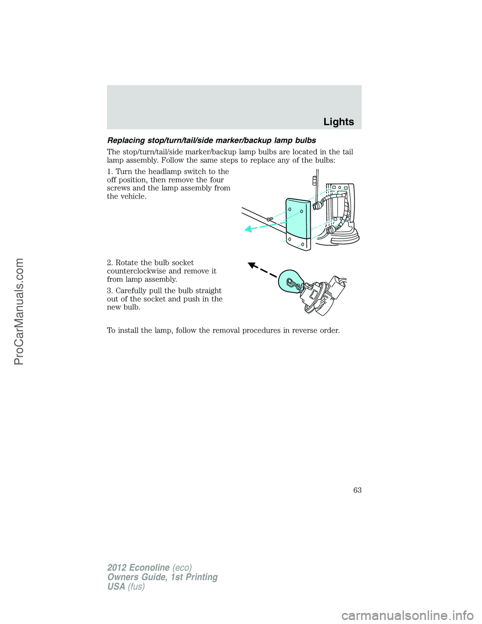
Replacing stop/turn/tail/side marker/backup lamp bulbs
The stop/turn/tail/side marker/backup lamp bulbs are located in the tail
lamp assembly. Follow the same steps to replace any of the bulbs:
1. Turn the headlamp switch to the
off position, then remove the four
screws and the lamp assembly from
the vehicle.
2. Rotate the bulb socket
counterclockwise and remove it
from lamp assembly.
3. Carefully pull the bulb straight
out of the socket and push in the
new bulb.
To install the lamp, follow the removal procedures in reverse order.
Lights
63
2012 Econoline(eco)
Owners Guide, 1st Printing
USA(fus)
ProCarManuals.com
Page 68 of 335
EXTERIOR MIRRORS
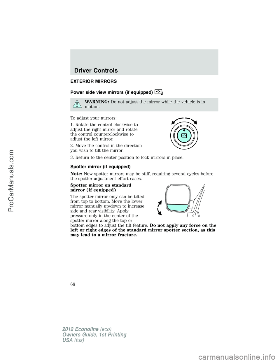
Power side view mirrors (if equipped)
WARNING:Do not adjust the mirror while the vehicle is in
motion.
To adjust your mirrors:
1. Rotate the control clockwise to
adjust the right mirror and rotate
the control counterclockwise to
adjust the left mirror.
2. Move the control in the direction
you wish to tilt the mirror.
3. Return to the center position to lock mirrors in place.
Spotter mirror (if equipped)
Note:New spotter mirrors may be stiff, requiring several cycles before
the spotter adjustment effort eases.
Spotter mirror on standard
mirror (if equipped)
The spotter mirror only can be tilted
from top to bottom. Move the lower
mirror manually up/down to increase
side and rear visibility. Apply
pressure only in the center of the
spotter mirror along the top or
bottom edges to adjust the tilt feature.Do not apply any force on the
left or right edges of the standard mirror spotter section, as this
may lead to a mirror fracture.
Driver Controls
68
2012 Econoline(eco)
Owners Guide, 1st Printing
USA(fus)
ProCarManuals.com
Page 91 of 335
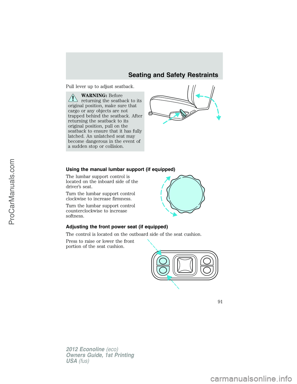
Pull lever up to adjust seatback.
WARNING:Before
returning the seatback to its
original position, make sure that
cargo or any objects are not
trapped behind the seatback. After
returning the seatback to its
original position, pull on the
seatback to ensure that it has fully
latched. An unlatched seat may
become dangerous in the event of
a sudden stop or collision.
Using the manual lumbar support (if equipped)
The lumbar support control is
located on the inboard side of the
driver’s seat.
Turn the lumbar support control
clockwise to increase firmness.
Turn the lumbar support control
counterclockwise to increase
softness.
Adjusting the front power seat (if equipped)
The control is located on the outboard side of the seat cushion.
Press to raise or lower the front
portion of the seat cushion.
Seating and Safety Restraints
91
2012 Econoline(eco)
Owners Guide, 1st Printing
USA(fus)
ProCarManuals.com
Page 163 of 335
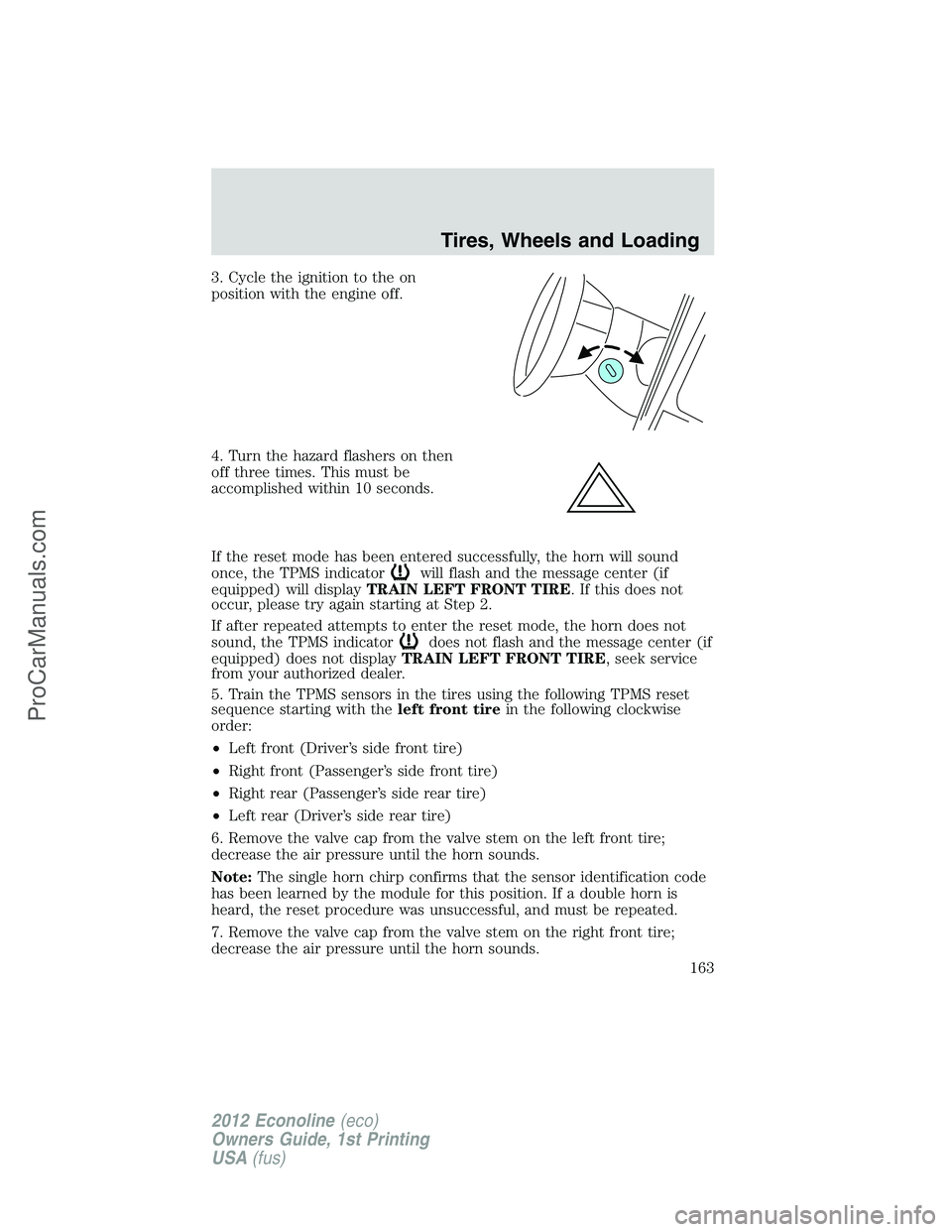
3. Cycle the ignition to the on
position with the engine off.
4. Turn the hazard flashers on then
off three times. This must be
accomplished within 10 seconds.
If the reset mode has been entered successfully, the horn will sound
once, the TPMS indicator
will flash and the message center (if
equipped) will displayTRAIN LEFT FRONT TIRE. If this does not
occur, please try again starting at Step 2.
If after repeated attempts to enter the reset mode, the horn does not
sound, the TPMS indicator
does not flash and the message center (if
equipped) does not displayTRAIN LEFT FRONT TIRE, seek service
from your authorized dealer.
5. Train the TPMS sensors in the tires using the following TPMS reset
sequence starting with theleft front tirein the following clockwise
order:
•Left front (Driver’s side front tire)
•Right front (Passenger’s side front tire)
•Right rear (Passenger’s side rear tire)
•Left rear (Driver’s side rear tire)
6. Remove the valve cap from the valve stem on the left front tire;
decrease the air pressure until the horn sounds.
Note:The single horn chirp confirms that the sensor identification code
has been learned by the module for this position. If a double horn is
heard, the reset procedure was unsuccessful, and must be repeated.
7. Remove the valve cap from the valve stem on the right front tire;
decrease the air pressure until the horn sounds.
Tires, Wheels and Loading
163
2012 Econoline(eco)
Owners Guide, 1st Printing
USA(fus)
ProCarManuals.com
Page 229 of 335
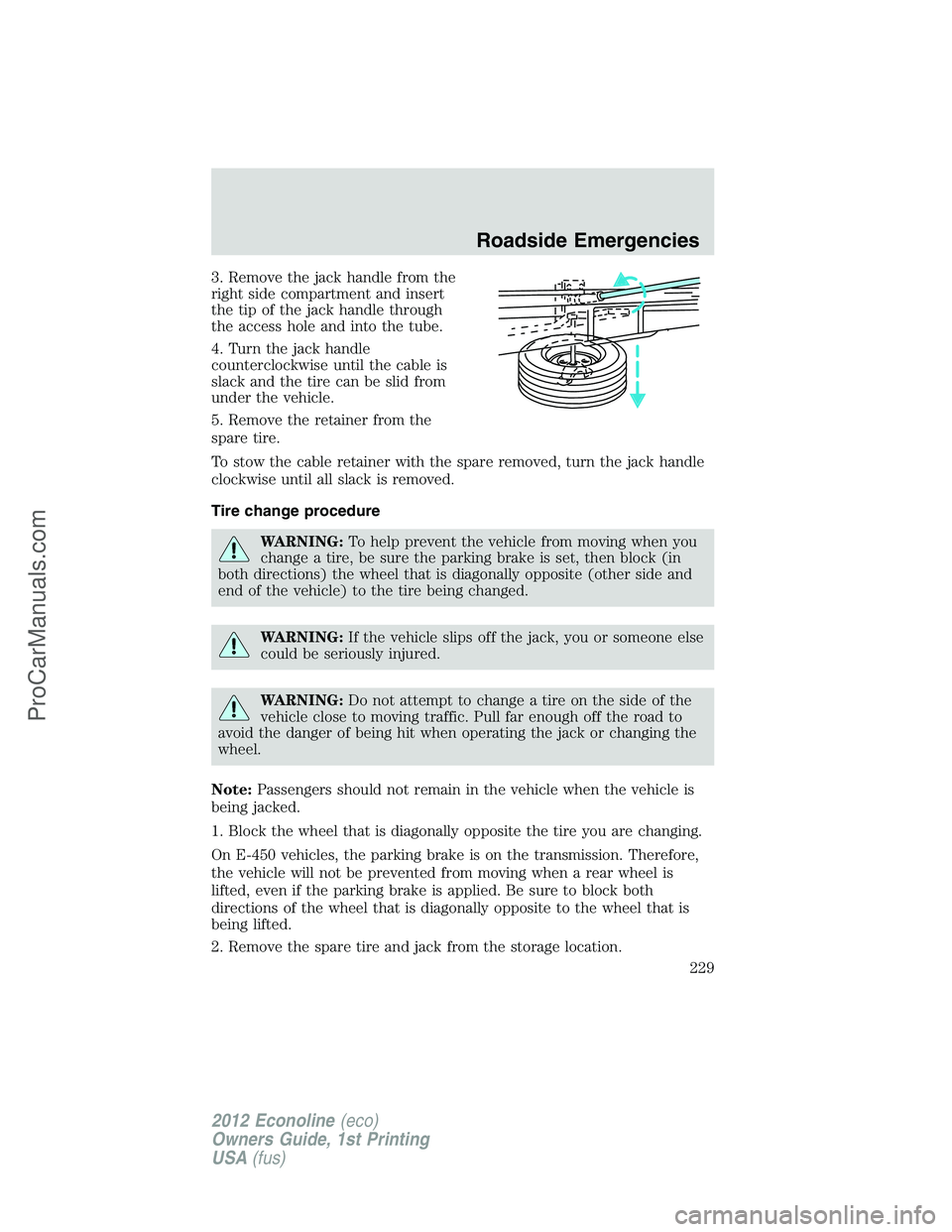
3. Remove the jack handle from the
right side compartment and insert
the tip of the jack handle through
the access hole and into the tube.
4. Turn the jack handle
counterclockwise until the cable is
slack and the tire can be slid from
under the vehicle.
5. Remove the retainer from the
spare tire.
To stow the cable retainer with the spare removed, turn the jack handle
clockwise until all slack is removed.
Tire change procedure
WARNING:To help prevent the vehicle from moving when you
change a tire, be sure the parking brake is set, then block (in
both directions) the wheel that is diagonally opposite (other side and
end of the vehicle) to the tire being changed.
WARNING:If the vehicle slips off the jack, you or someone else
could be seriously injured.
WARNING:Do not attempt to change a tire on the side of the
vehicle close to moving traffic. Pull far enough off the road to
avoid the danger of being hit when operating the jack or changing the
wheel.
Note:Passengers should not remain in the vehicle when the vehicle is
being jacked.
1. Block the wheel that is diagonally opposite the tire you are changing.
On E-450 vehicles, the parking brake is on the transmission. Therefore,
the vehicle will not be prevented from moving when a rear wheel is
lifted, even if the parking brake is applied. Be sure to block both
directions of the wheel that is diagonally opposite to the wheel that is
being lifted.
2. Remove the spare tire and jack from the storage location.
Roadside Emergencies
229
2012 Econoline(eco)
Owners Guide, 1st Printing
USA(fus)
ProCarManuals.com
Page 230 of 335
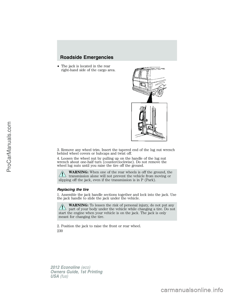
•The jack is located in the rear
right-hand side of the cargo area.
3. Remove any wheel trim. Insert the tapered end of the lug nut wrench
behind wheel covers or hubcaps and twist off.
4. Loosen the wheel nut by pulling up on the handle of the lug nut
wrench about one-half turn (counterclockwise). Do not remove the
wheel lug nuts until you raise the tire off the ground.
WARNING:When one of the rear wheels is off the ground, the
transmission alone will not prevent the vehicle from moving or
slipping off the jack, even if the transmission is in P (Park).
Replacing the tire
1. Assemble the jack handle sections together and lock into the jack. Use
the jack handle to slide the jack under the vehicle.
WARNING:To lessen the risk of personal injury, do not put any
part of your body under the vehicle while changing a tire. Do not
start the engine when your vehicle is on the jack. The jack is only
meant for changing the tire.
2. Position the jack to raise the front or rear wheel.
Roadside Emergencies
230
2012 Econoline(eco)
Owners Guide, 1st Printing
USA(fus)
ProCarManuals.com
Page 232 of 335
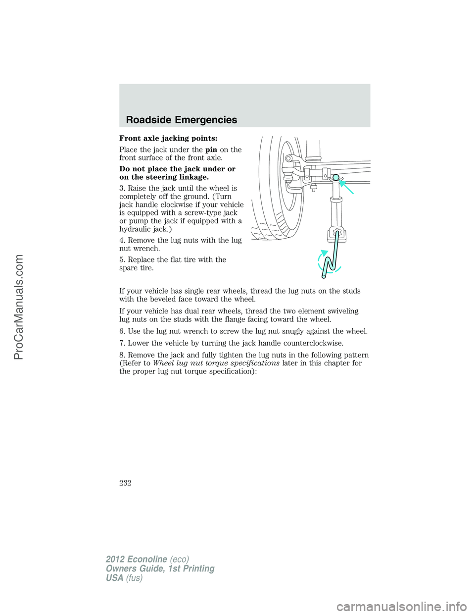
Front axle jacking points:
Place the jack under thepinon the
front surface of the front axle.
Do not place the jack under or
on the steering linkage.
3. Raise the jack until the wheel is
completely off the ground. (Turn
jack handle clockwise if your vehicle
is equipped with a screw-type jack
or pump the jack if equipped with a
hydraulic jack.)
4. Remove the lug nuts with the lug
nut wrench.
5. Replace the flat tire with the
spare tire.
If your vehicle has single rear wheels, thread the lug nuts on the studs
with the beveled face toward the wheel.
If your vehicle has dual rear wheels, thread the two element swiveling
lug nuts on the studs with the flange facing toward the wheel.
6. Use the lug nut wrench to screw the lug nut snugly against the wheel.
7. Lower the vehicle by turning the jack handle counterclockwise.
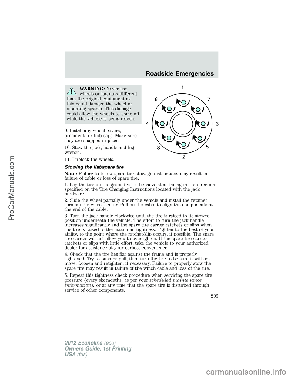
8. Remove the jack and fully tighten the lug nuts in the following pattern
(Refer toWheel lug nut torque specificationslater in this chapter for
the proper lug nut torque specification):
Roadside Emergencies
232
2012 Econoline(eco)
Owners Guide, 1st Printing
USA(fus)
ProCarManuals.com
Page 233 of 335
WARNING:Never use
wheels or lug nuts different
than the original equipment as
this could damage the wheel or
mounting system. This damage
could allow the wheels to come off
while the vehicle is being driven.
9. Install any wheel covers,
ornaments or hub caps. Make sure
they are snapped in place.
10. Stow the jack, handle and lug
wrench.
11. Unblock the wheels.
Stowing the flat/spare tire
Note:Failure to follow spare tire stowage instructions may result in
failure of cable or loss of spare tire.
1. Lay the tire on the ground with the valve stem facing in the direction
specified on the Tire Changing Instructions located with the jack
hardware.
2. Slide the wheel partially under the vehicle and install the retainer
through the wheel center. Pull on the cable to align the components at
the end of the cable.
3. Turn the jack handle clockwise until the tire is raised to its stowed
position underneath the vehicle. The effort to turn the jack handle
increases significantly and the spare tire carrier ratchets or slips when
the tire is raised to the maximum tightness. Tighten to the best of your
ability, to the point where the ratchet/slip occurs, if possible. The spare
tire carrier will not allow you to overtighten. If the spare tire carrier
ratchets or slips with little effort, take the vehicle to your authorized
dealer for assistance at your earliest convenience.
4. Check that the tire lies flat against the frame and is properly
tightened. Try to push or pull, then turn the tire to be sure it will not
move. Loosen and retighten, if necessary. Failure to properly stow the
spare tire may result in failure of the winch cable and loss of the tire.
5. Repeat this tightness check procedure when servicing the spare tire
pressure (every six months, as per yourscheduled maintenance
information),or at any time that the spare tire is disturbed through
service of other components.
Roadside Emergencies
233
2012 Econoline(eco)
Owners Guide, 1st Printing
USA(fus)
ProCarManuals.com
Page 261 of 335
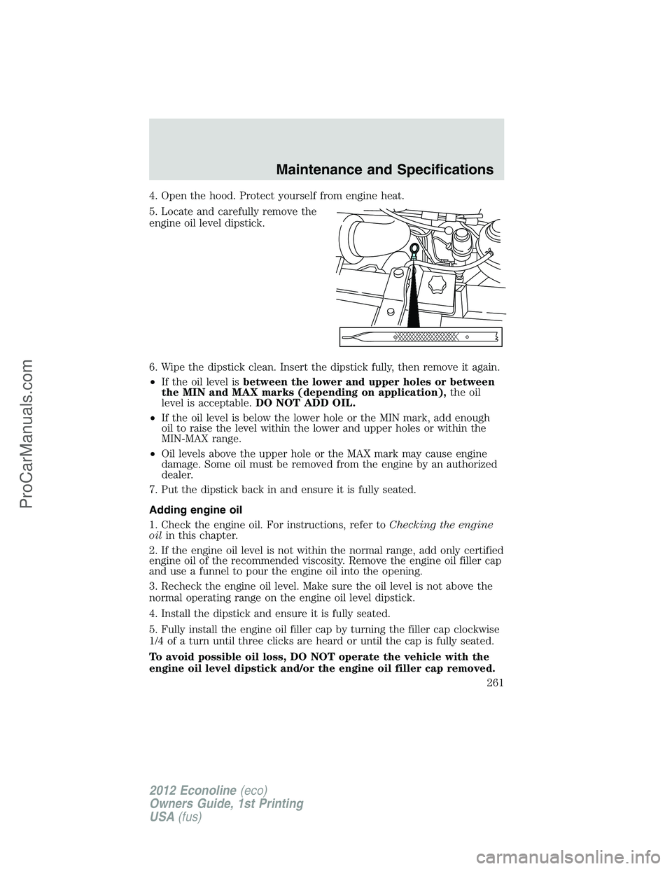
4. Open the hood. Protect yourself from engine heat.
5. Locate and carefully remove the
engine oil level dipstick.
6. Wipe the dipstick clean. Insert the dipstick fully, then remove it again.
•If the oil level isbetween the lower and upper holes or between
the MIN and MAX marks (depending on application),the oil
level is acceptable.DO NOT ADD OIL.
•If the oil level is below the lower hole or the MIN mark, add enough
oil to raise the level within the lower and upper holes or within the
MIN-MAX range.
•Oil levels above the upper hole or the MAX mark may cause engine
damage. Some oil must be removed from the engine by an authorized
dealer.
7. Put the dipstick back in and ensure it is fully seated.
Adding engine oil
1. Check the engine oil. For instructions, refer toChecking the engine
oilin this chapter.
2. If the engine oil level is not within the normal range, add only certified
engine oil of the recommended viscosity. Remove the engine oil filler cap
and use a funnel to pour the engine oil into the opening.
3. Recheck the engine oil level. Make sure the oil level is not above the
normal operating range on the engine oil level dipstick.
4. Install the dipstick and ensure it is fully seated.
5. Fully install the engine oil filler cap by turning the filler cap clockwise
1/4 of a turn until three clicks are heard or until the cap is fully seated.
To avoid possible oil loss, DO NOT operate the vehicle with the
engine oil level dipstick and/or the engine oil filler cap removed.
Maintenance and Specifications
261
2012 Econoline(eco)
Owners Guide, 1st Printing
USA(fus)
ProCarManuals.com
Page 265 of 335
Because your vehicle’s engine is electronically controlled by a computer,
some control conditions are maintained by power from the battery. When
the battery is disconnected or a new battery is installed, the engine must
relearn its idle and fuel trim strategy for optimum driveability and
performance. Flexible fuel vehicles (FFV) must also relearn the ethanol
content of the fuel for optimum driveability and performance. To begin
this process:
1. With the vehicle at a complete stop, set the parking brake.
2. Put the gearshift in P (Park), turn off all accessories and start the
engine.
3. Run the engine until it reaches normal operating temperature.
4. Allow the engine to idle for at least one minute.
5. Turn the A/C on and allow the engine to idle for at least one minute.
6. Release the parking brake. With your foot on the brake pedal and with
the A/C on, put the vehicle in D (Drive) and allow the engine to idle for
at least one minute.
7. Drive the vehicle to complete the relearning process.
•The vehicle may need to be driven 10 miles (16 km) or more to
relearn the idle and fuel trim strategy along with the ethanol content
for flexible fuel vehicles.
•If you do not allow the engine to relearn its idle trim, the idle
quality of your vehicle may be adversely affected until the idle
trim is eventually relearned.
•For flexible fuel vehicles, if you are operating on E85, you may
experience poor starts or an inability to start the engine and
driveability problems until the fuel trim and ethanol content have been
relearned.
If the battery has been disconnected or a new battery has been installed,
the clock and radio settings must be reset once the battery is
reconnected.
Maintenance and Specifications
265
2012 Econoline(eco)
Owners Guide, 1st Printing
USA(fus)
ProCarManuals.com