battery FORD E-350 2002 Owners Manual
[x] Cancel search | Manufacturer: FORD, Model Year: 2002, Model line: E-350, Model: FORD E-350 2002Pages: 256, PDF Size: 3.52 MB
Page 3 of 256
Cleaning 191
Underbody preservation 195
Maintenance and Specifications 198
Engine compartment 199
Engine oil 201
Battery 204
Fuel information 216
Air filter(s) 229
Part numbers 235
Refill capacities 236
Lubricant specifications 240
Accessories 248
Index 251
All rights reserved. Reproduction by any means, electronic or mechanical
including photocopying, recording or by any information storage and retrieval
system or translation in whole or part is not permitted without written
authorization from Ford Motor Company. Ford may change the contents without
notice and without incurring obligation.
Copyright © 2002 Ford Motor Company
Table of Contents
3
ProCarManuals.com
Page 9 of 256
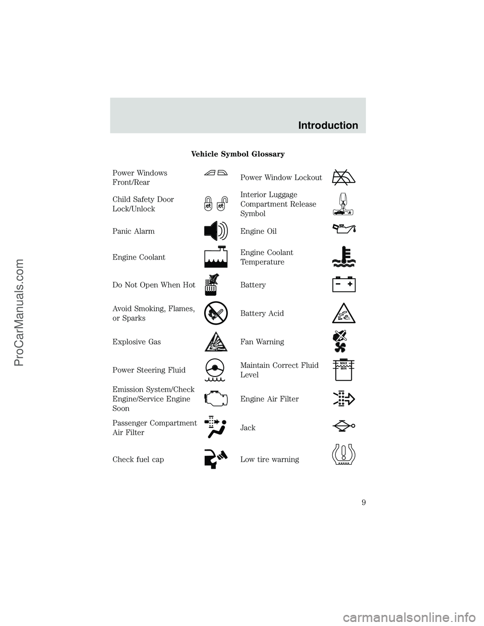
Vehicle Symbol Glossary
Power Windows
Front/Rear
Power Window Lockout
Child Safety Door
Lock/UnlockInterior Luggage
Compartment Release
Symbol
Panic AlarmEngine Oil
Engine CoolantEngine Coolant
Temperature
Do Not Open When HotBattery
Avoid Smoking, Flames,
or SparksBattery Acid
Explosive GasFan Warning
Power Steering FluidMaintain Correct Fluid
LevelMAX
MIN
Emission System/Check
Engine/Service Engine
Soon
Engine Air Filter
Passenger Compartment
Air FilterJack
Check fuel capLow tire warning
Introduction
9
ProCarManuals.com
Page 12 of 256
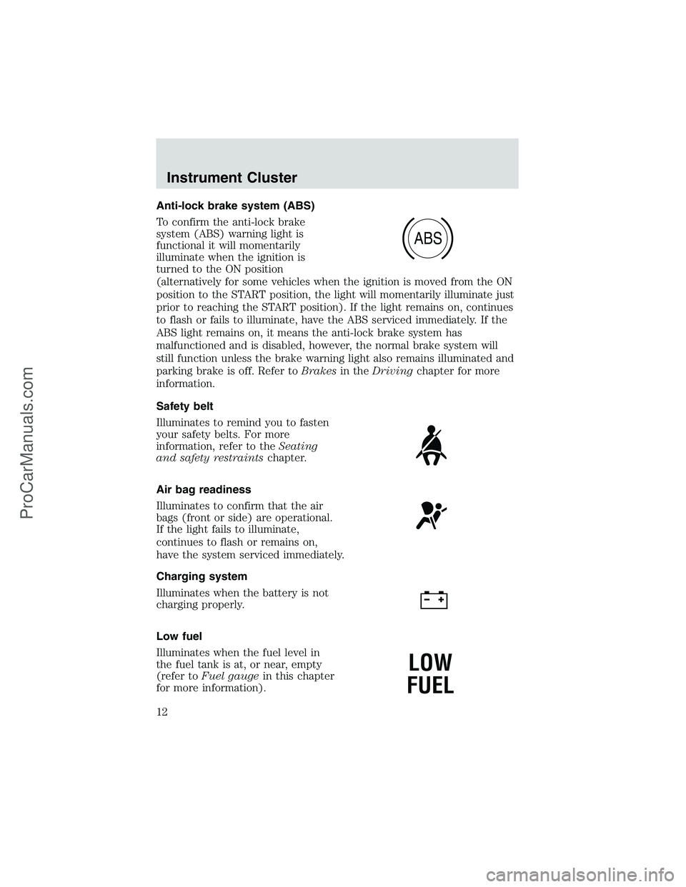
Anti-lock brake system (ABS)
To confirm the anti-lock brake
system (ABS) warning light is
functional it will momentarily
illuminate when the ignition is
turned to the ON position
(alternatively for some vehicles when the ignition is moved from the ON
position to the START position, the light will momentarily illuminate just
prior to reaching the START position). If the light remains on, continues
to flash or fails to illuminate, have the ABS serviced immediately. If the
ABS light remains on, it means the anti-lock brake system has
malfunctioned and is disabled, however, the normal brake system will
still function unless the brake warning light also remains illuminated and
parking brake is off. Refer toBrakesin theDrivingchapter for more
information.
Safety belt
Illuminates to remind you to fasten
your safety belts. For more
information, refer to theSeating
and safety restraintschapter.
Air bag readiness
Illuminates to confirm that the air
bags (front or side) are operational.
If the light fails to illuminate,
continues to flash or remains on,
have the system serviced immediately.
Charging system
Illuminates when the battery is not
charging properly.
Low fuel
Illuminates when the fuel level in
the fuel tank is at, or near, empty
(refer toFuel gaugein this chapter
for more information).
ABS
LOW
FUEL
Instrument Cluster
12
ProCarManuals.com
Page 15 of 256
Never remove the coolant reservoir cap while the engine is
running or hot. Steam and scalding liquid from a hot cooling
system can burn you badly.
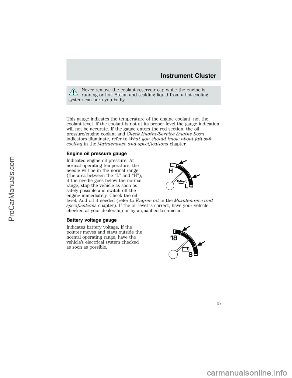
This gauge indicates the temperature of the engine coolant, not the
coolant level. If the coolant is not at its proper level the gauge indication
will not be accurate. If the gauge enters the red section, the oil
pressure/engine coolant andCheck Engine/Service Engine Soon
indicators illuminate, refer toWhat you should know about fail-safe
coolingin theMaintenance and specificationschapter.
Engine oil pressure gauge
Indicates engine oil pressure. At
normal operating temperature, the
needle will be in the normal range
(the area between the“L”and“H”);
if the needle goes below the normal
range, stop the vehicle as soon as
safely possible and switch off the
engine immediately. Check the oil
level. Add oil if needed (refer toEngine oilin theMaintenance and
specificationschapter). If the oil level is correct, have your vehicle
checked at your dealership or by a qualified technician.
Battery voltage gauge
Indicates battery voltage. If the
pointer moves and stays outside the
normal operating range, have the
vehicle’s electrical system checked
as soon as possible.
18
8
Instrument Cluster
15
ProCarManuals.com
Page 54 of 256
7.PLAYbutton
Press to play the tape.
8.REWbutton
Press to rewind the tape.
9.FFbutton
Press to fast forward the tape.
10.STOPbutton
Press to stop the tape.
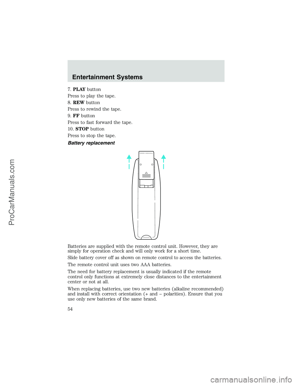
Battery replacement
Batteries are supplied with the remote control unit. However, they are
simply for operation check and will only work for a short time.
Slide battery cover off as shown on remote control to access the batteries.
The remote control unit uses two AAA batteries.
The need for battery replacement is usually indicated if the remote
control only functions at extremely close distances to the entertainment
center or not at all.
When replacing batteries, use two new batteries (alkaline recommended)
and install with correct orientation (+ and � polarities). Ensure that you
use only new batteries of the same brand.
Entertainment Systems
54
ProCarManuals.com
Page 59 of 256
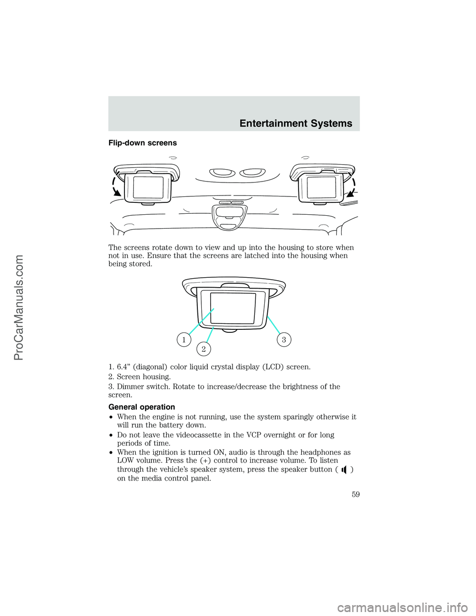
Flip-down screens
The screens rotate down to view and up into the housing to store when
not in use. Ensure that the screens are latched into the housing when
being stored.
1. 6.4”(diagonal) color liquid crystal display (LCD) screen.
2. Screen housing.
3. Dimmer switch. Rotate to increase/decrease the brightness of the
screen.
General operation
•When the engine is not running, use the system sparingly otherwise it
will run the battery down.
•Do not leave the videocassette in the VCP overnight or for long
periods of time.
•When the ignition is turned ON, audio is through the headphones as
LOW volume. Press the (+) control to increase volume. To listen
through the vehicle’s speaker system, press the speaker button (
)
on the media control panel.
13
2
Entertainment Systems
59
ProCarManuals.com
Page 99 of 256
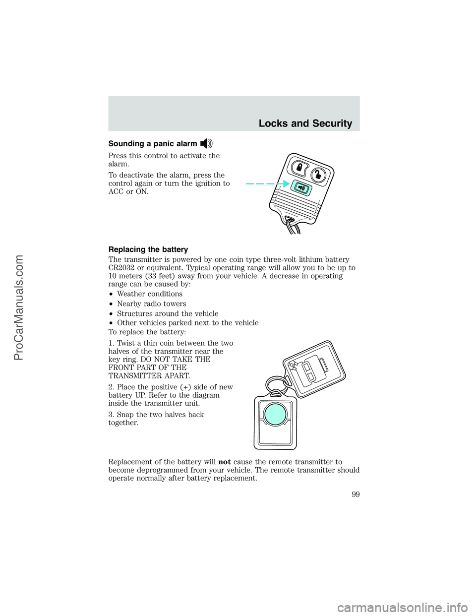
Sounding a panic alarm
Press this control to activate the
alarm.
To deactivate the alarm, press the
control again or turn the ignition to
ACC or ON.
Replacing the battery
The transmitter is powered by one coin type three-volt lithium battery
CR2032 or equivalent. Typical operating range will allow you to be up to
10 meters (33 feet) away from your vehicle. A decrease in operating
range can be caused by:
•Weather conditions
•Nearby radio towers
•Structures around the vehicle
•Other vehicles parked next to the vehicle
To replace the battery:
1. Twist a thin coin between the two
halves of the transmitter near the
key ring. DO NOT TAKE THE
FRONT PART OF THE
TRANSMITTER APART.
2. Place the positive (+) side of new
battery UP. Refer to the diagram
inside the transmitter unit.
3. Snap the two halves back
together.
Replacement of the battery willnotcause the remote transmitter to
become deprogrammed from your vehicle. The remote transmitter should
operate normally after battery replacement.
Locks and Security
99
ProCarManuals.com
Page 148 of 256
1 (First)
Use 1 (Low) to provide maximum
engine braking on steep
downgrades. Upshifts can be made
by shifting to 2 (Second) or to
(Overdrive). Selecting 1 (Low) at higher speeds causes the transmission
to shift to a lower gear, and will shift to 1 (Low) after vehicle decelerates
to the proper speed.
Forced Downshifts
To gain acceleration in
(Overdrive) or Drive (O/D OFF) when
passing another vehicle, push the accelerator to the floor. The
transmission will downshift to the appropriate gear: third, second or first
gear.
Shift strategy (4R100 automatic transmission)
To account for customer driving habits and conditions, your 4R100
automatic transmission electronically controls the shift quality by using
an adaptive learning strategy. The adaptive learning strategy is
maintained by power from the battery. When the battery is disconnected
or a new battery is installed, the transmission must relearn its adaptive
strategy. Optimal shifting will resume within a few hundred kilometers
(miles) of operation.
If the shift quality does not improve within a few hundred
kilometers (miles) of operation, or if the downshifts and other
throttle conditions do not function normally, see your dealer or a
qualified service technician as soon as possible.
DRIVING THROUGH WATER
Do not drive quickly through standing water, especially if the depth is
unknown. Traction or brake capability may be limited and if the ignition
system gets wet, your engine may stall. Water may also enter your
engine’s air intake and severely damage your engine.
If driving through deep or standing water is unavoidable, proceed very
slowly. Never drive through water that is higher than the bottom of the
hubs (for trucks) or the bottom of the wheel rims (for cars).
Once through the water, always try the brakes. Wet brakes do not stop
the vehicle as effectively as dry brakes. Drying can be improved by
moving your vehicle slowly while applying light pressure on the brake
pedal.
Driving through deep water where the transmission vent tube is
submerged may allow water into the transmission and cause
Driving
148
ProCarManuals.com
Page 164 of 256
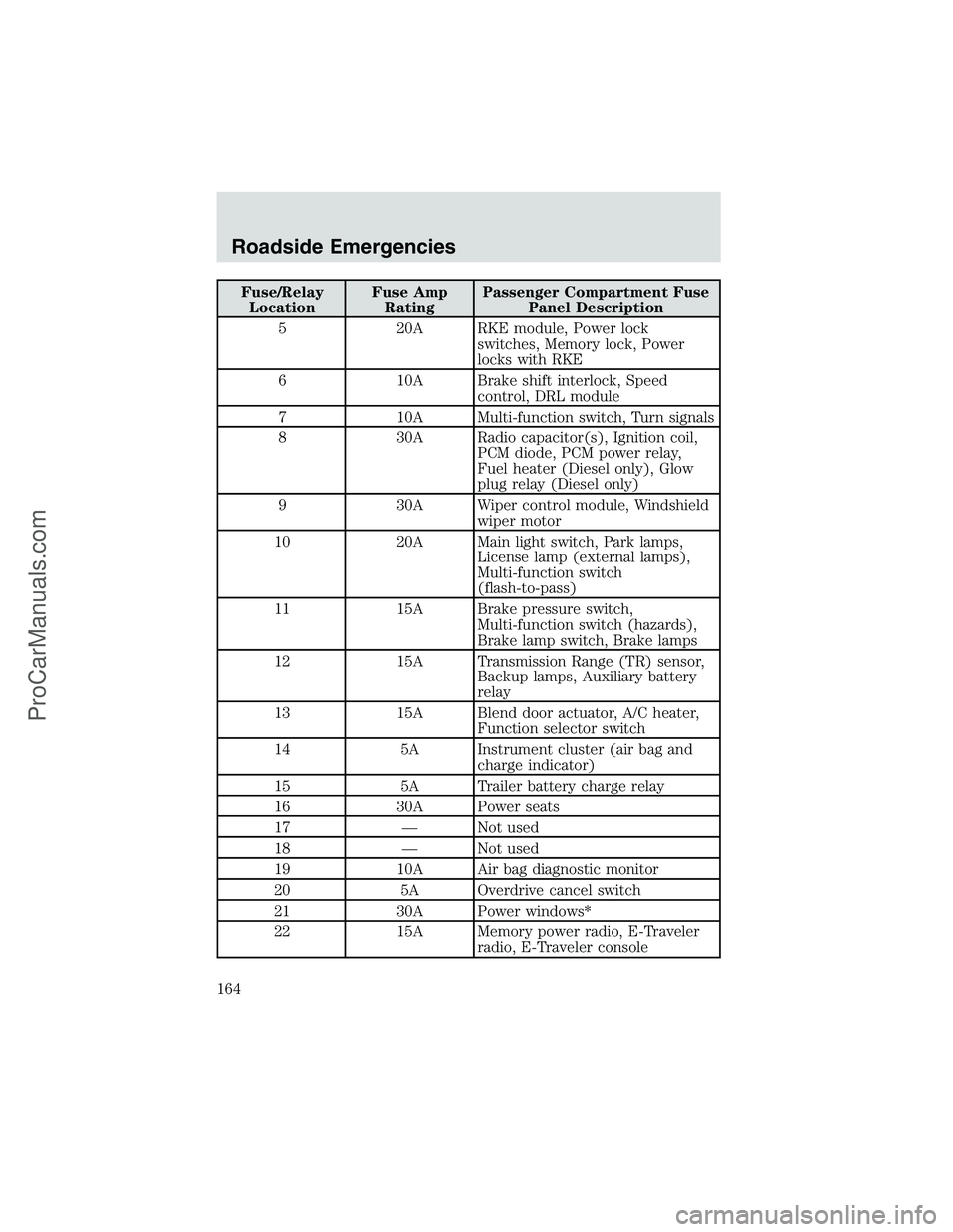
Fuse/Relay
LocationFuse Amp
RatingPassenger Compartment Fuse
Panel Description
5 20A RKE module, Power lock
switches, Memory lock, Power
locks with RKE
6 10A Brake shift interlock, Speed
control, DRL module
7 10A Multi-function switch, Turn signals
8 30A Radio capacitor(s), Ignition coil,
PCM diode, PCM power relay,
Fuel heater (Diesel only), Glow
plug relay (Diesel only)
9 30A Wiper control module, Windshield
wiper motor
10 20A Main light switch, Park lamps,
License lamp (external lamps),
Multi-function switch
(flash-to-pass)
11 15A Brake pressure switch,
Multi-function switch (hazards),
Brake lamp switch, Brake lamps
12 15A Transmission Range (TR) sensor,
Backup lamps, Auxiliary battery
relay
13 15A Blend door actuator, A/C heater,
Function selector switch
14 5A Instrument cluster (air bag and
charge indicator)
15 5A Trailer battery charge relay
16 30A Power seats
17—Not used
18—Not used
19 10A Air bag diagnostic monitor
20 5A Overdrive cancel switch
21 30A Power windows*
22 15A Memory power radio, E-Traveler
radio, E-Traveler console
Roadside Emergencies
164
ProCarManuals.com
Page 166 of 256
Always disconnect the battery before servicing high current
fuses.
Always replace the cover to the power distribution box before
reconnecting the battery or refilling fluid reservoirs
If the battery has been disconnected and reconnected, refer to the
Batterysection of theMaintenance and specificationschapter.
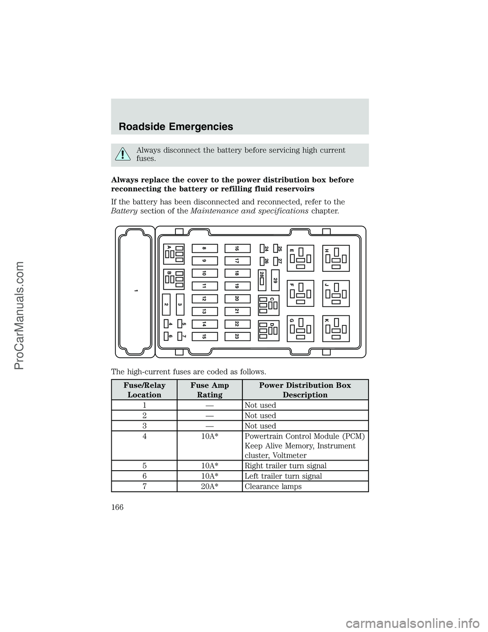
The high-current fuses are coded as follows.
Fuse/Relay
LocationFuse Amp
RatingPower Distribution Box
Description
1—Not used
2—Not used
3—Not used
4 10A* Powertrain Control Module (PCM)
Keep Alive Memory, Instrument
cluster, Voltmeter
5 10A* Right trailer turn signal
6 10A* Left trailer turn signal
7 20A* Clearance lamps
AB3
2
146 5715 14 13 12 11 10 9 823 22 21 20 19 18 17 1624 26 25 27
29
CDG F EK J H
28
Roadside Emergencies
166
ProCarManuals.com