FORD E-450 2004 Owners Manual
Manufacturer: FORD, Model Year: 2004, Model line: E-450, Model: FORD E-450 2004Pages: 240, PDF Size: 3.8 MB
Page 131 of 240
When backing down a ramp during boat launching or retrieval:
•do not allow the static water level to rise above the bottom edge of
the rear bumper.
•do not allow waves to break higher than 15 cm (6 inches) above the
bottom edge of the rear bumper.
Exceeding these limits may allow water to enter vehicle components:
•causing internal damage to the components.
•affecting driveability, emissions and reliability.
Replace the rear axle lubricant any time the axle has been submerged in
water. Rear axle lubricant quantities are not to be checked or changed
unless a leak is suspected or repair required.
RECREATIONAL TOWING (ALL WHEELS ON THE GROUND)
An example of recreational towing would be towing your vehicle on a
trip behind a motorhome. Follow these guidelines if you have the need
for recreational towing of your vehicle with all four wheels on the
ground. These guidelines are designed to ensure that your transmission
is not damaged.
2WD vehicles (with automatic transmissions):
•Place the transmission in N (Neutral)
•Maximum speed is 56 km (35 mph)
•Maximum distance is 80 km (50 miles)
If a distance of 80 km (50 miles) or a speed of 56 km (35 mph) must be
exceeded, the drive shaft will have to be removed.
Ford recommends the driveshaft be removed/installed only by a qualified
technician. See your local dealer for driveshaft removal/installation.
Improper removal/installation of the driveshaft can cause
transmission fluid loss, damage to the driveshaft and internal
transmission components.
2004 Econoline(eco)
Owners Guide (post-2002-fmt)
USA English(fus)
Driving
131
ProCarManuals.com
Page 132 of 240
GETTING ROADSIDE ASSISTANCE
To fully assist you should you have a vehicle concern, Ford Motor
Company offers a complimentary roadside assistance program. This
program is separate from the New Vehicle Limited Warranty. The service
is available:
•24–hours, seven days a week
•for the New Vehicle Limited Warranty period of three years or 60,000
km (36,000 miles), whichever occurs first on Ford and Mercury
vehicles, and four years or 80,000 km (50,000 miles) on Lincoln
vehicles.
Roadside assistance will cover:
•changing a flat tire
•jump-starts
•lock-out assistance
•limited fuel delivery
•towing of your disabled vehicle to the nearest Ford Motor Company
dealership, or your selling dealer if within 56.3 km (35 miles) of the
nearest Ford Motor Company dealership (one tow per disablement).
Even non-warranty related tows, like accidents or getting stuck in the
mud or snow, are covered (some exclusions apply, such as impound
towing or repossession).
Canadian customers refer to your Owner Information Guide for
information on:
•coverage period
•exact fuel amounts
•towing of your disabled vehicle
•emergency travel expense reimbursement
•travel planning benefits
USING ROADSIDE ASSISTANCE
Complete the roadside assistance identification card and place it in your
wallet for quick reference. In the United States, this card is found in the
Owner Guide portfolio in the glove compartment in Ford vehicles and is
mailed to you if you own a Mercury or Lincoln. In Canada, the card is
found in the Owner Information Guide in the glove compartment.
U.S. Ford or Mercury vehicle customers who require roadside assistance,
call 1–800–241–3673; Lincoln vehicle customers call 1–800–521–4140.
2004 Econoline(eco)
Owners Guide (post-2002-fmt)
USA English(fus)
Roadside Emergencies
132
ProCarManuals.com
Page 133 of 240
Canadian customers who require roadside assistance, call
1–800–665–2006.
If you need to arrange roadside assistance for yourself, Ford Motor
Company will reimburse a reasonable amount. To obtain reimbursement
information, U.S. Ford or Mercury vehicles customers call
1-800-241-3673; Lincoln vehicle customers call 1–800–521–4140.
Canadian customers who need to obtain reimbursement information, call
1–800–665–2006.
ROADSIDE COVERAGE BEYOND BASIC WARRANTY
In the United States, you may purchase additional roadside assistance
coverage beyond this period through the Ford Auto Club by contacting
your Ford or Lincoln Mercury dealer.
Similarly in Canada, for uninterrupted Roadside Assistance coverage, you
may purchase extended coverage prior to your Basic Warranty’s Roadside
Assistance expiring. For more information and enrollment, contact
1–877–294–2582 or visit our website at www.ford.ca.
HAZARD FLASHER
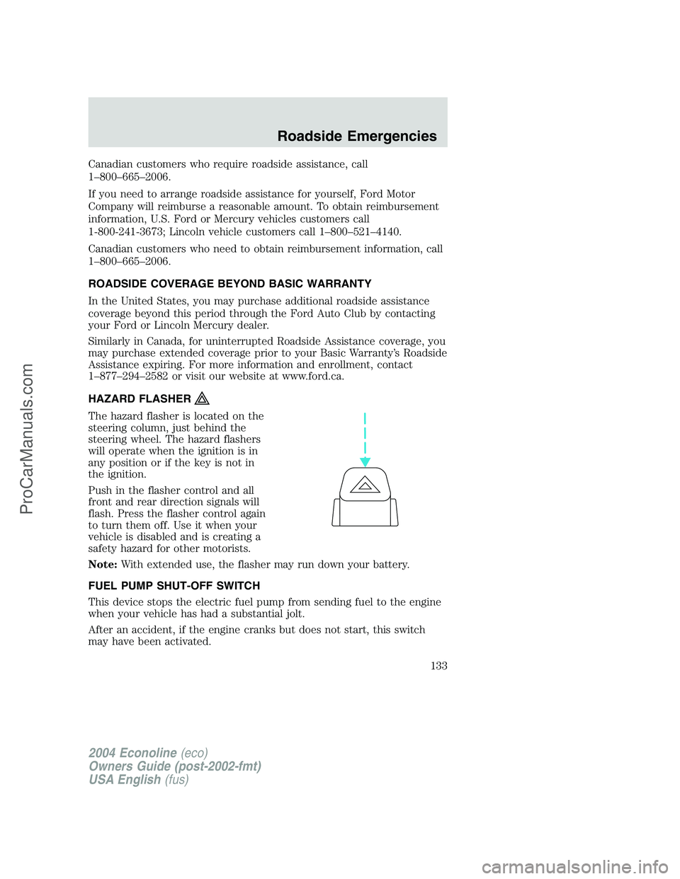
The hazard flasher is located on the
steering column, just behind the
steering wheel. The hazard flashers
will operate when the ignition is in
any position or if the key is not in
the ignition.
Push in the flasher control and all
front and rear direction signals will
flash. Press the flasher control again
to turn them off. Use it when your
vehicle is disabled and is creating a
safety hazard for other motorists.
Note:With extended use, the flasher may run down your battery.
FUEL PUMP SHUT-OFF SWITCH
This device stops the electric fuel pump from sending fuel to the engine
when your vehicle has had a substantial jolt.
After an accident, if the engine cranks but does not start, this switch
may have been activated.
2004 Econoline(eco)
Owners Guide (post-2002-fmt)
USA English(fus)
Roadside Emergencies
133
ProCarManuals.com
Page 134 of 240
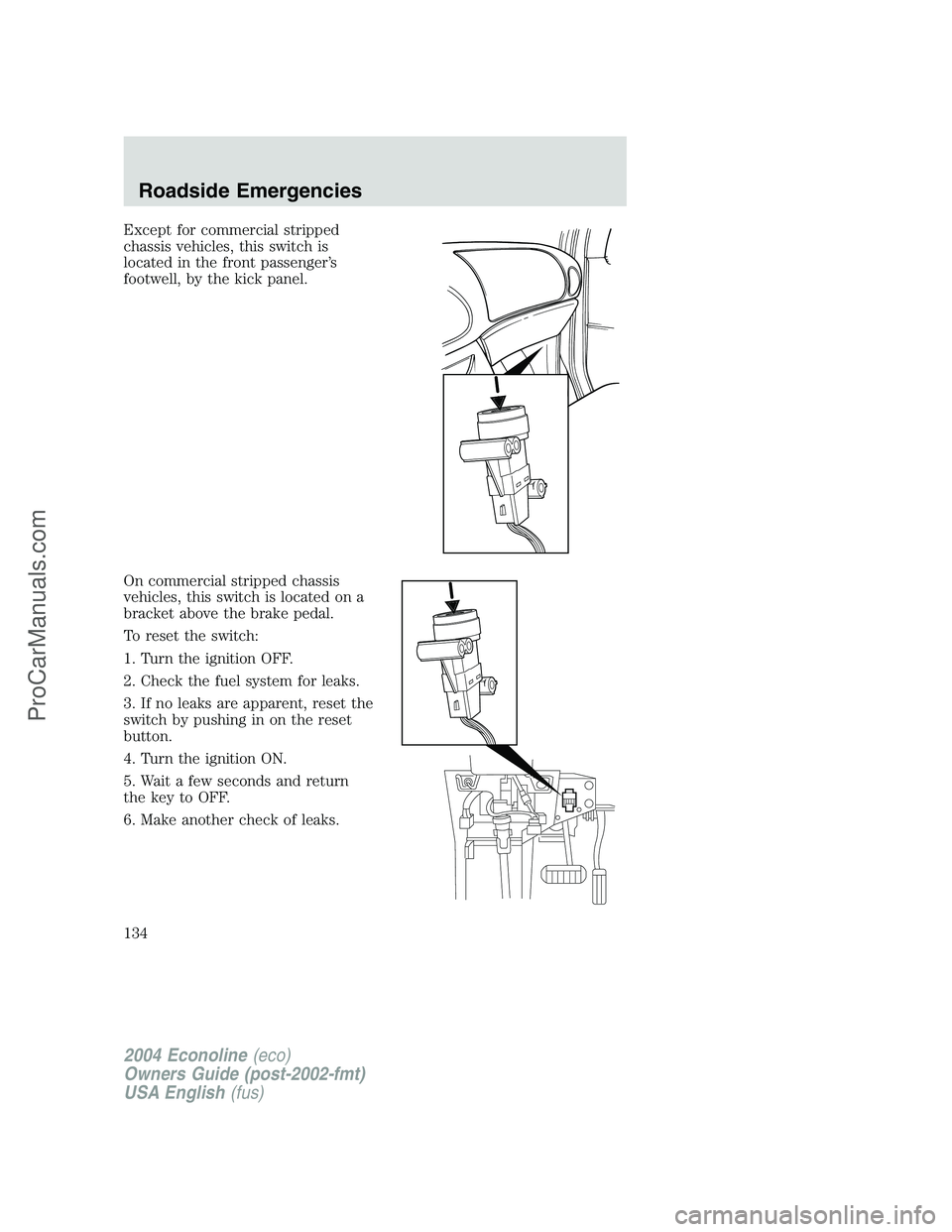
Except for commercial stripped
chassis vehicles, this switch is
located in the front passenger’s
footwell, by the kick panel.
On commercial stripped chassis
vehicles, this switch is located on a
bracket above the brake pedal.
To reset the switch:
1. Turn the ignition OFF.
2. Check the fuel system for leaks.
3. If no leaks are apparent, reset the
switch by pushing in on the reset
button.
4. Turn the ignition ON.
5. Wait a few seconds and return
the key to OFF.
6. Make another check of leaks.
2004 Econoline(eco)
Owners Guide (post-2002-fmt)
USA English(fus)
Roadside Emergencies
134
ProCarManuals.com
Page 135 of 240
FUSES AND RELAYS
Fuses
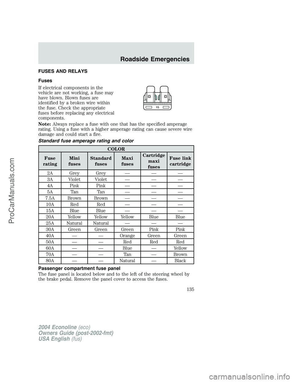
If electrical components in the
vehicle are not working, a fuse may
have blown. Blown fuses are
identified by a broken wire within
the fuse. Check the appropriate
fuses before replacing any electrical
components.
Note:Always replace a fuse with one that has the specified amperage
rating. Using a fuse with a higher amperage rating can cause severe wire
damage and could start a fire.
Standard fuse amperage rating and color
COLOR
Fuse
ratingMini
fusesStandard
fusesMaxi
fusesCartridge
maxi
fusesFuse link
cartridge
2A Grey Grey———
3A Violet Violet———
4A Pink Pink———
5A Tan Tan———
7.5A Brown Brown———
10A Red Red———
15A Blue Blue———
20A Yellow Yellow Yellow Blue Blue
25A Natural Natural———
30A Green Green Green Pink Pink
40A——Orange Green Green
50A——Red Red Red
60A——Blue—Yellow
70A——Ta n—Brown
80A——Natural—Black
Passenger compartment fuse panel
The fuse panel is located below and to the left of the steering wheel by
the brake pedal. Remove the panel cover to access the fuses.
15
2004 Econoline(eco)
Owners Guide (post-2002-fmt)
USA English(fus)
Roadside Emergencies
135
ProCarManuals.com
Page 136 of 240
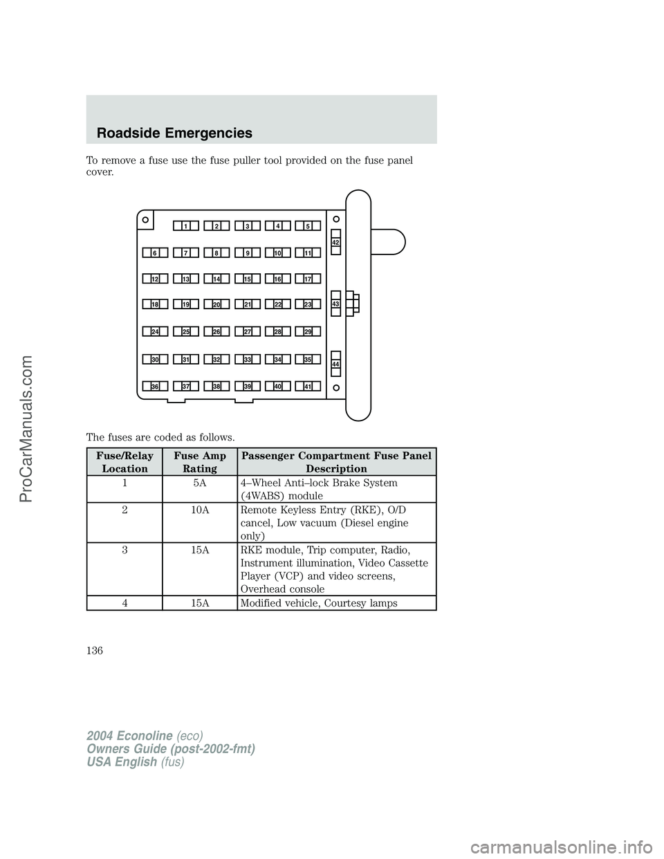
To remove a fuse use the fuse puller tool provided on the fuse panel
cover.
The fuses are coded as follows.
Fuse/RelayLocation Fuse Amp
Rating Passenger Compartment Fuse Panel
Description
1 5A 4–Wheel Anti–lock Brake System (4WABS) module
2 10A Remote Keyless Entry (RKE), O/D cancel, Low vacuum (Diesel engine
only)
3 15A RKE module, Trip computer, Radio, Instrument illumination, Video Cassette
Player (VCP) and video screens,
Overhead console
4 15A Modified vehicle, Courtesy lamps
1234 5
7
68910 1142
43
44
13
12 14
15 16 17
19
18
2021 22 23
25
24
26 27 28 29
31
30 32 33 34 35
37
36 38 39
40
41
2004 Econoline (eco)
Owners Guide (post-2002-fmt)
USA English (fus)
Roadside Emergencies
136
ProCarManuals.com
Page 137 of 240
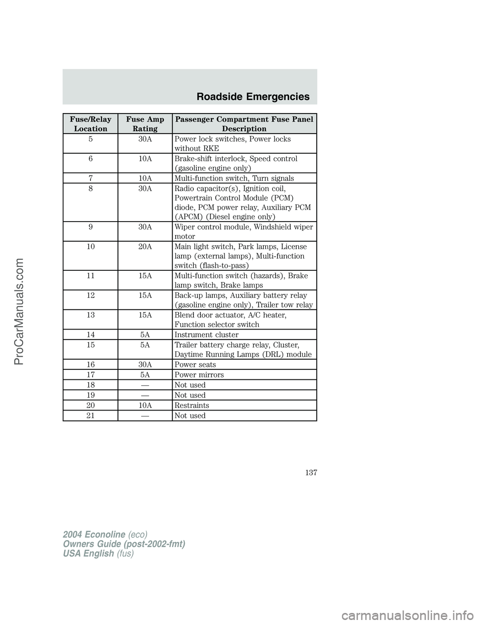
Fuse/RelayLocation Fuse Amp
Rating Passenger Compartment Fuse Panel
Description
5 30A Power lock switches, Power locks without RKE
6 10A Brake-shift interlock, Speed control (gasoline engine only)
7 10A Multi-function switch, Turn signals
8 30A Radio capacitor(s), Ignition coil, Powertrain Control Module (PCM)
diode, PCM power relay, Auxiliary PCM
(APCM) (Diesel engine only)
9 30A Wiper control module, Windshield wiper motor
10 20A Main light switch, Park lamps, License lamp (external lamps), Multi-function
switch (flash-to-pass)
11 15A Multi-function switch (hazards), Brake lamp switch, Brake lamps
12 15A Back-up lamps, Auxiliary battery relay (gasoline engine only), Trailer tow relay
13 15A Blend door actuator, A/C heater, Function selector switch
14 5A Instrument cluster
15 5A Trailer battery charge relay, Cluster, Daytime Running Lamps (DRL) module
16 30A Power seats
17 5A Power mirrors
18 —Not used
19 —Not used
20 10A Restraints
21 —Not used
2004 Econoline (eco)
Owners Guide (post-2002-fmt)
USA English (fus)
Roadside Emergencies
137
ProCarManuals.com
Page 138 of 240
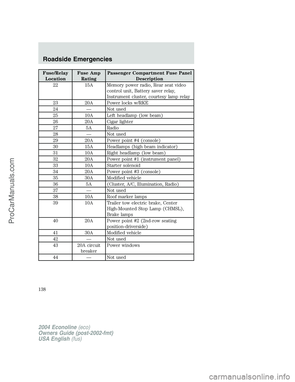
Fuse/RelayLocation Fuse Amp
Rating Passenger Compartment Fuse Panel
Description
22 15A Memory power radio, Rear seat video control unit, Battery saver relay,
Instrument cluster, courtesy lamp relay
23 20A Power locks w/RKE
24 —Not used
25 10A Left headlamp (low beam)
26 20A Cigar lighter
27 5A Radio
28 —Not used
29 20A Power point #4 (console)
30 15A Headlamps (high beam indicator)
31 10A Right headlamp (low beam)
32 20A Power point #1 (instrument panel)
33 10A Starter solenoid
34 20A Power point #3 (console)
35 30A Modified vehicle
36 5A (Cluster, A/C, Illumination, Radio)
37 —Not used
38 10A Roof marker lamps
39 10A Trailer tow electric brake, Center High-Mounted Stop Lamp (CHMSL),
Brake lamps
40 20A Power point #2 (2nd-row seating position-driverside)
41 30A Modified vehicle
42 —Not used
43 20A circuit breakerPower windows
44 —Not used
2004 Econoline (eco)
Owners Guide (post-2002-fmt)
USA English (fus)
Roadside Emergencies
138
ProCarManuals.com
Page 139 of 240
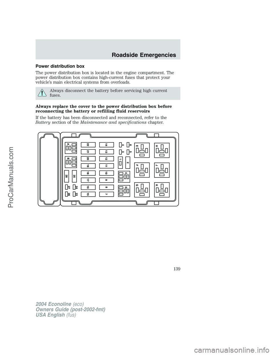
Power distribution box
The power distribution box is located in the engine compartment. The
power distribution box contains high-current fuses that protect your
vehicle’s main electrical systems from overloads.
Always disconnect the battery before servicing high current
fuses.
Always replace the cover to the power distribution box before
reconnecting the battery or refilling fluid reservoirs
If the battery has been disconnected and reconnected, refer to the
Batterysection of theMaintenance and specificationschapter.
2004 Econoline(eco)
Owners Guide (post-2002-fmt)
USA English(fus)
Roadside Emergencies
139
ProCarManuals.com
Page 140 of 240
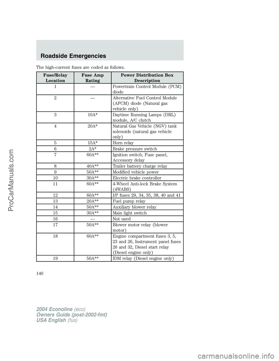
The high-current fuses are coded as follows.
Fuse/RelayLocation Fuse Amp
Rating Power Distribution Box
Description
1 — Powertrain Control Module (PCM) diode
2 — Alternative Fuel Control Module (AFCM) diode (Natural gas
vehicle only)
3 10A* Daytime Running Lamps (DRL) module, A/C clutch
4 20A* Natural Gas Vehicle (NGV) tank solenoids (natural gas vehicle
only)
5 15A* Horn relay
6 2A* Brake pressure switch
7 60A** Ignition switch, Fuse panel, Accessory delay
8 40A** Trailer battery charge relay
9 50A** Modified vehicle power
10 30A** Electric brake controller
11 60A** 4-Wheel Anti-lock Brake System (4WABS)
12 60A** I/P fuses 29, 34, 35, 38, 40 and 41
13 20A** Fuel pump relay
14 50A** Auxiliary blower relay
15 30A** Main light switch
16 — Not used
17 50A** Blower motor relay (blower motor)
18 60A** Engine compartment fuses 3, 5, 23 and 26, Instrument panel fuses
26 and 32, Diesel start relay
(Diesel engine only)
19 50A** IDM relay (Diesel engine only)
2004 Econoline (eco)
Owners Guide (post-2002-fmt)
USA English (fus)
Roadside Emergencies
140
ProCarManuals.com