heater FORD E SERIES 1998 4.G Owners Manual
[x] Cancel search | Manufacturer: FORD, Model Year: 1998, Model line: E SERIES, Model: FORD E SERIES 1998 4.GPages: 144, PDF Size: 2.14 MB
Page 14 of 144

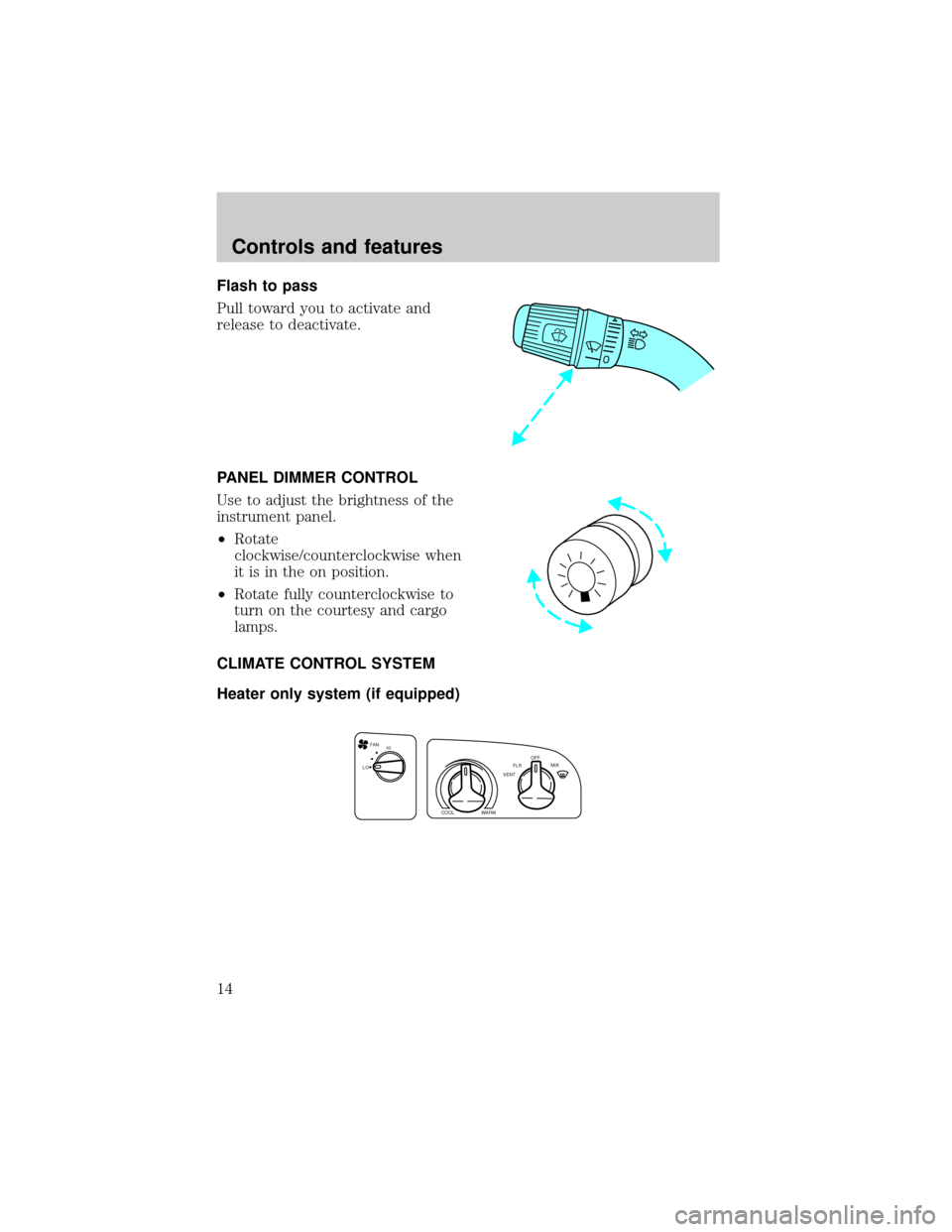
Flash to pass
Pull toward you to activate and
release to deactivate.
PANEL DIMMER CONTROL
Use to adjust the brightness of the
instrument panel.
²Rotate
clockwise/counterclockwise when
it is in the on position.
²Rotate fully counterclockwise to
turn on the courtesy and cargo
lamps.
CLIMATE CONTROL SYSTEM
Heater only system (if equipped)
FAN
LOHI
COOLWARM
VENTFLROFF
MIX
Controls and features
14
Page 15 of 144

Fan speed control
Controls the volume of air circulated
in the vehicle.
Temperature control knob
Controls the temperature of the
airflow inside the vehicle. On
heater-only systems, the air cannot
be cooled below the outside
temperature.
Mode selector control
Controls the direction of the airflow
to the inside of the vehicle.
²VENT-Distributes outside air through the instrument panel registers.
²FLR-Allows for maximum heating. Distributes outside air through the
floor ducts.
²OFF-Outside air is shut out and the fan will not operate.
²MIX-Distributes outside air through the floor ducts and the windshield
defroster ducts.
²
-Distributes outside air through the windshield defroster ducts.
It can be used to clear ice or fog from the windshield.
FAN
LOHI
COOLWARM
VENTFLROFF
MIX
Controls and features
15
Page 19 of 144

²To prevent humidity buildup inside the vehicle, don't drive with the
climate control system in the OFF position.
²Don't put objects under the front seat that will interfere with the
airflow to the back seats.
²Remove any snow, ice or leaves
from the air intake area (at the
bottom of the windshield).
²If your vehicle has been parked with the windows closed during hot
weather, the air conditioner will do a much faster job of cooling if you
drive for two or three minutes with the windows open. This will force
most of the hot, stale air out of the vehicle. Then operate your air
conditioner as you would normally.
²When placing objects on top of your instrument panel, be careful to
not place them over the defroster outlets. These objects can block
airflow and reduce your ability to see through your windshield. Also,
avoid placing small objects on top of your instrument panel. These
objects can fall down into the defroster outlets and block airflow and
possibly damage your climate control system.
Auxiliary heater and air conditioner (if equipped)
If your vehicle is equipped with a factory installed auxiliary unit, the
front control panel will include separate controls for the front and rear
fans.
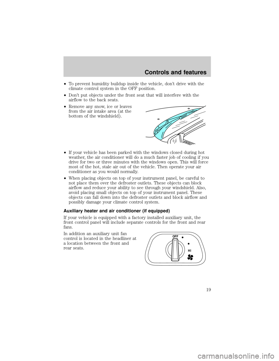
In addition an auxiliary unit fan
control is located in the headliner at
a location between the front and
rear seats.
OFF
HI
Controls and features
19
Page 61 of 144

Make sure the corresponding lights illuminate briefly. If a light fails to
illuminate, have the vehicle serviced.
²If the driver's safety belt is fastened, the light (
) will not illuminate.
STARTING THE ENGINE
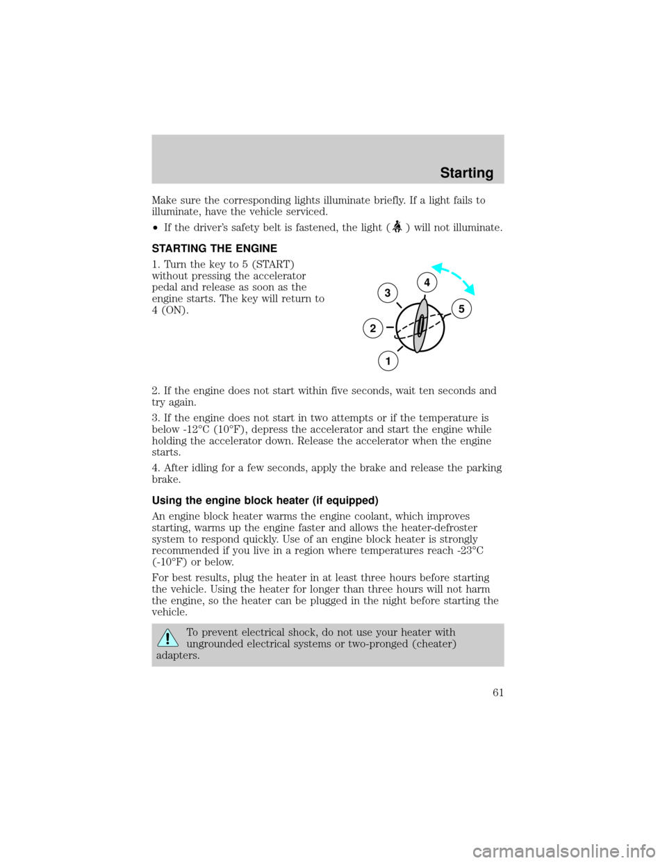
1. Turn the key to 5 (START)
without pressing the accelerator
pedal and release as soon as the
engine starts. The key will return to
4 (ON).
2. If the engine does not start within five seconds, wait ten seconds and
try again.
3. If the engine does not start in two attempts or if the temperature is
below -12ÉC (10ÉF), depress the accelerator and start the engine while
holding the accelerator down. Release the accelerator when the engine
starts.
4. After idling for a few seconds, apply the brake and release the parking
brake.
Using the engine block heater (if equipped)
An engine block heater warms the engine coolant, which improves
starting, warms up the engine faster and allows the heater-defroster
system to respond quickly. Use of an engine block heater is strongly
recommended if you live in a region where temperatures reach -23ÉC
(-10ÉF) or below.
For best results, plug the heater in at least three hours before starting
the vehicle. Using the heater for longer than three hours will not harm
the engine, so the heater can be plugged in the night before starting the
vehicle.
To prevent electrical shock, do not use your heater with
ungrounded electrical systems or two-pronged (cheater)
adapters.
3
2
1
5
4
Starting
61
Page 81 of 144

Fuse/Relay
LocationFuse Amp
RatingDescription
6 10A Shift Interlock, Speed Control, DRL Module
7 10A Multi-Function Switch, Turn Signals
8 30A Radio Capacitor(s), Ignition Coil, PCM Diode,
PCM Power Relay, Fuel Heater, Glow Plug
Relay (Diesel)
9 30A Wiper Control Module, Windshield Wiper
Motor
10 20A Main Light Switch, (External Lamps)
Multi-Function Switch (Flash-to-pass)
11 15A Brake Pressure Switch, Multi-Function Switch
(Hazards), RABS, Brake Pedal Position
Switch
12 15A Transmission Range (TR) Sensor, Auxiliary
Battery Relay
13 15A Blend Door Actuator, Function Selector
Switch
14 5A Instrument Cluster (Air Bag and Charge
Indicator)
15 5A Trailer Battery Charge Relay
16 30A Power Seats
17 Ð Not Used
18 Ð Not Used
19 10A Air Bag Diagnostic Monitor
20 5A Overdrive Cancel Switch
21 30A Power Windows*
22 15A Memory Power Radio
23 20A Cigar Lighter, Data Link Connector (DLC)
24 5A Illuminated Entry Module
25 10A Left Headlamp (Low Beam)
26 - Not Used
27 5A Radio
28 25A Power Plug
Roadside emergencies
81
Page 91 of 144

Model Bolt Size Wheel Lug nut Torque*
N²M Ft-Lb
E-150 1/2-20 135 100
E-250, E-350 and
E-Super Duty9/16-18 190 140
* Torque specifications are for nut and bolt threads free of dirt and
rust. Do not use oil or grease on threads. Use only Ford recommended
replacement fasteners.
JUMP STARTING YOUR VEHICLE
The gases around the battery can explode if exposed to flames,
sparks, or lit cigarettes. An explosion could result in injury or
vehicle damage.
Do not push start your vehicle. You could damage the catalytic
converter.
Batteries contain sulfuric acid which burns skin, eyes, and
clothing.
Preparing your vehicle
Also see the label on the battery.
1. Use only a 12±volt supply to start your vehicle. If you connect your
battery to a 24±volt power supply you can damage your starter, ignition
system and other electrical components.
2. Do not disconnect the battery of the disabled vehicle as this could
damage the vehicle's electrical system.
3. Park the booster vehicle close to the hood of the disabled vehicle
making sure theydo nottouch. Set the parking brake on both vehicles
and stay clear of the engine cooling fan and other moving parts.
4. Check all battery terminals and remove any excessive corrosion before
you attach the battery cables.
5. Turn the heater fan on in both vehicles to protect any electrical
surges. Turn all other accessories off.
Roadside emergencies
91
Page 140 of 144

Aiming headlamps ....................125
Air bag supplemental
restraint system ..........................46
and child safety seats ..............47
description ................................46
disposal ......................................49
indicator light ...........................48
passenger air bag .....................47
Air conditioning
manual heating and air
conditioning system .......16,17,18
Anti-lock brake system (ABS)
description ................................64
Battery .......................................108
voltage gauge ............................12
Brake fluid
checking and adding ..............100
Brakes ..........................................63
anti-lock .....................................63
anti-lock brake system (ABS)
warning light .............................63
fluid, checking and adding ....100
Brake-shift interlock ...................65
Break-in period .............................2
Bulbs, replacing ........................122
headlamps ...............................123
specifications ..........................125
Changing a tire ...........................85
Child safety seats ........................51
Chime
headlamps on ..............................9
Cleaning your vehicle ...............125
engine compartment ..............127
fabric ........................................128
instrument panel ....................128
plastic parts ............................127
safety belts ..............................128
tail lamps .................................128
washing ....................................126
waxing .....................................126
wheels ......................................126
windows ..................................128Controls .......................................20
Emission control system ..........121
Engine ........................................134
check engine temperature
warning, message center .........96
service points ............................96
Engine block heater ...................61
Engine coolant
checking and adding .......101,102
disposal ....................................103
refill capacities ........................103
Engine oil ...............................97,99
changing oil and oil filter .........99
checking and adding ...........97,99
Exhaust fumes ............................62
Fail safe cooling ........................103
Fuel
calculating fuel economy .......120
improving fuel economy ..........76
octane rating ...........................119
quality ......................................120
running out of fuel .................120
safety information relating
to automotive fuels ................118
Fuel gauge ...................................10
Fuel pump shut-off switch .........77
Fuse panels
instrument panel ......................79
power distribution box .............82
Fuses ............................................79
Gauges, Mechanical ....................10
engine coolant temperature
gauge .........................................11
Hazard flashers ...........................77
Headlamps ...................................13
daytime running lights .............13
flashing ......................................14
high beam .................................13
Heating ........................................14
High beams
indicator light .............................9
Index
140