relay FORD E SERIES 2003 4.G Owners Manual
[x] Cancel search | Manufacturer: FORD, Model Year: 2003, Model line: E SERIES, Model: FORD E SERIES 2003 4.GPages: 232, PDF Size: 3.4 MB
Page 2 of 232
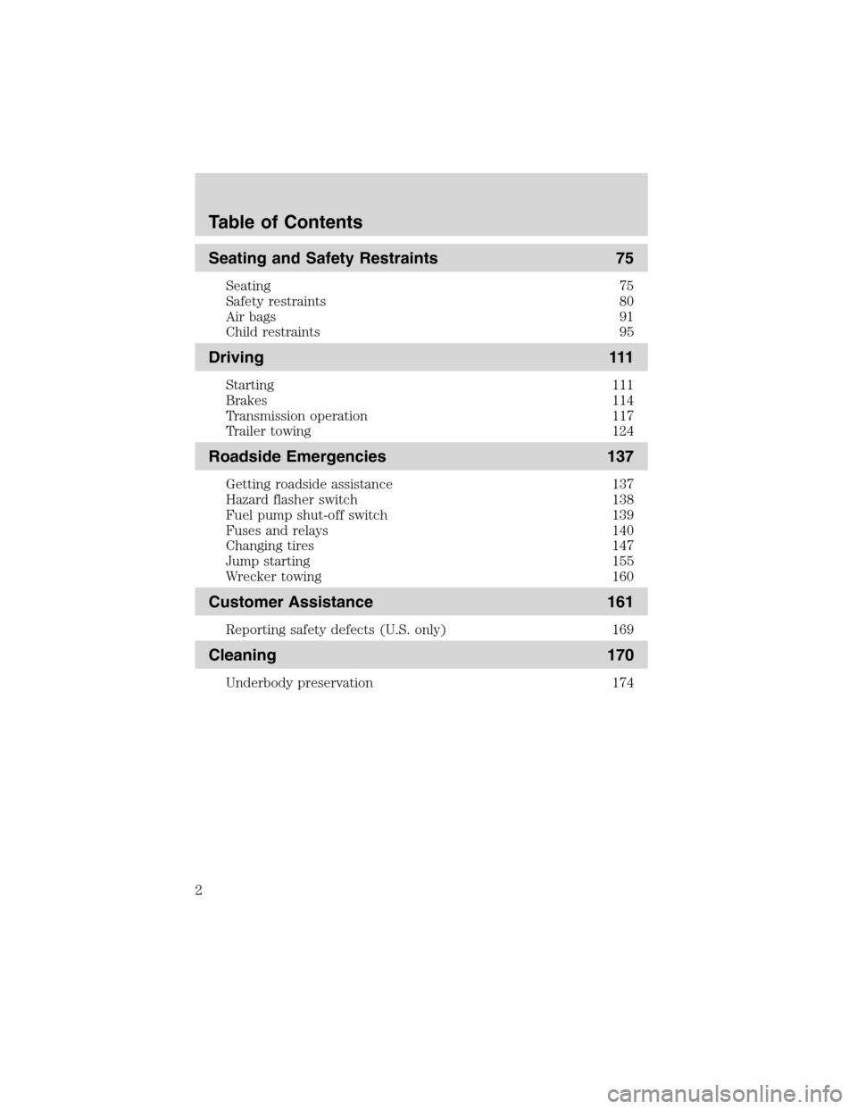
Seating and Safety Restraints 75
Seating 75
Safety restraints 80
Air bags 91
Child restraints 95
Driving 111
Starting 111
Brakes 114
Transmission operation 117
Trailer towing 124
Roadside Emergencies 137
Getting roadside assistance 137
Hazard flasher switch 138
Fuel pump shut-off switch 139
Fuses and relays 140
Changing tires 147
Jump starting 155
Wrecker towing 160
Customer Assistance 161
Reporting safety defects (U.S. only) 169
Cleaning 170
Underbody preservation 174
Table of Contents
2
Page 118 of 232
In the ignition OFF position, the automatic transmission shift
lever can be moved from the P (Park) position without the brake
pedal depressed. To avoid unwanted vehicle movement, always set the
parking brake.
3. Start the vehicle.
If it is necessary to use the above procedure to move the gearshift lever,
it is possible that a fuse has blown or the vehicle’s brakelamps are not
operating properly. Refer toFuses and relaysin theRoadside
emergencieschapter.
Do not drive your vehicle until you verify that the brakelamps
are working.
Always set the parking brake fully and make sure the gearshift is
latched in P (Park). Turn the ignition to the LOCK position and
remove the key whenever you leave your vehicle.
If the parking brake is fully released, but the brake warning lamp
remains illuminated, the brakes may not be working properly.
See your dealer or a qualified service technician.
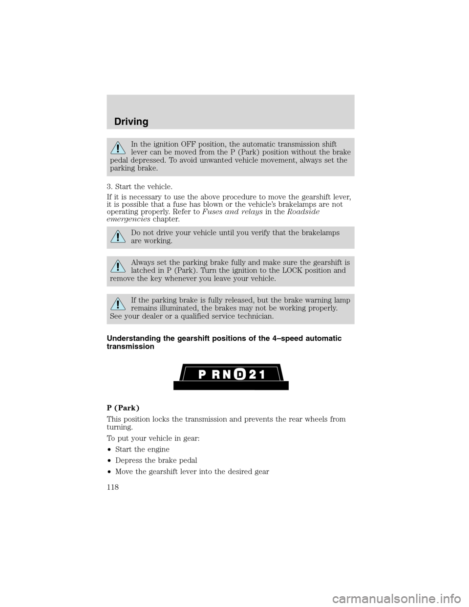
Understanding the gearshift positions of the 4–speed automatic
transmission
P (Park)
This position locks the transmission and prevents the rear wheels from
turning.
To put your vehicle in gear:
•Start the engine
•Depress the brake pedal
•Move the gearshift lever into the desired gear
Driving
118
Page 140 of 232
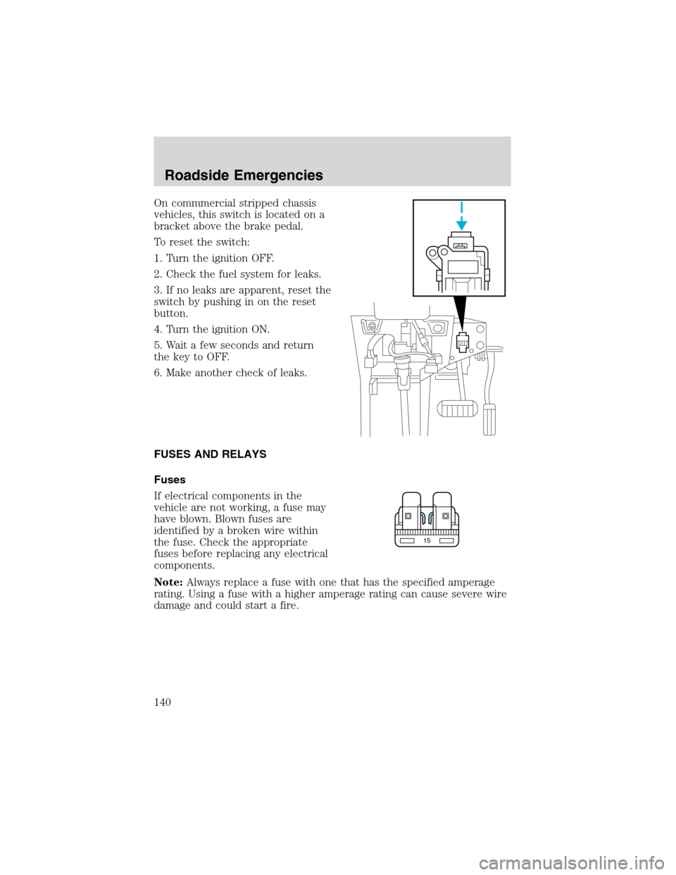
On commmercial stripped chassis
vehicles, this switch is located on a
bracket above the brake pedal.
To reset the switch:
1. Turn the ignition OFF.
2. Check the fuel system for leaks.
3. If no leaks are apparent, reset the
switch by pushing in on the reset
button.
4. Turn the ignition ON.
5. Wait a few seconds and return
the key to OFF.
6. Make another check of leaks.
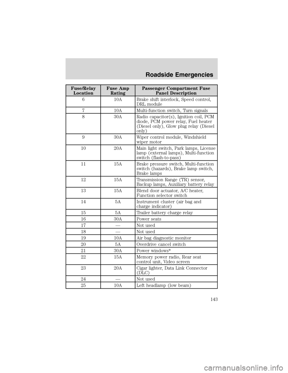
FUSES AND RELAYS
Fuses
If electrical components in the
vehicle are not working, a fuse may
have blown. Blown fuses are
identified by a broken wire within
the fuse. Check the appropriate
fuses before replacing any electrical
components.
Note:Always replace a fuse with one that has the specified amperage
rating. Using a fuse with a higher amperage rating can cause severe wire
damage and could start a fire.
15
Roadside Emergencies
140
Page 142 of 232
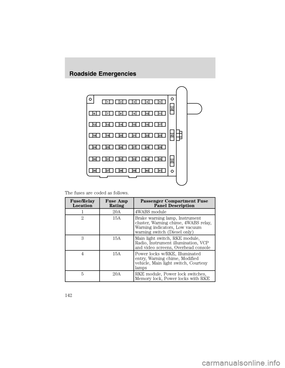
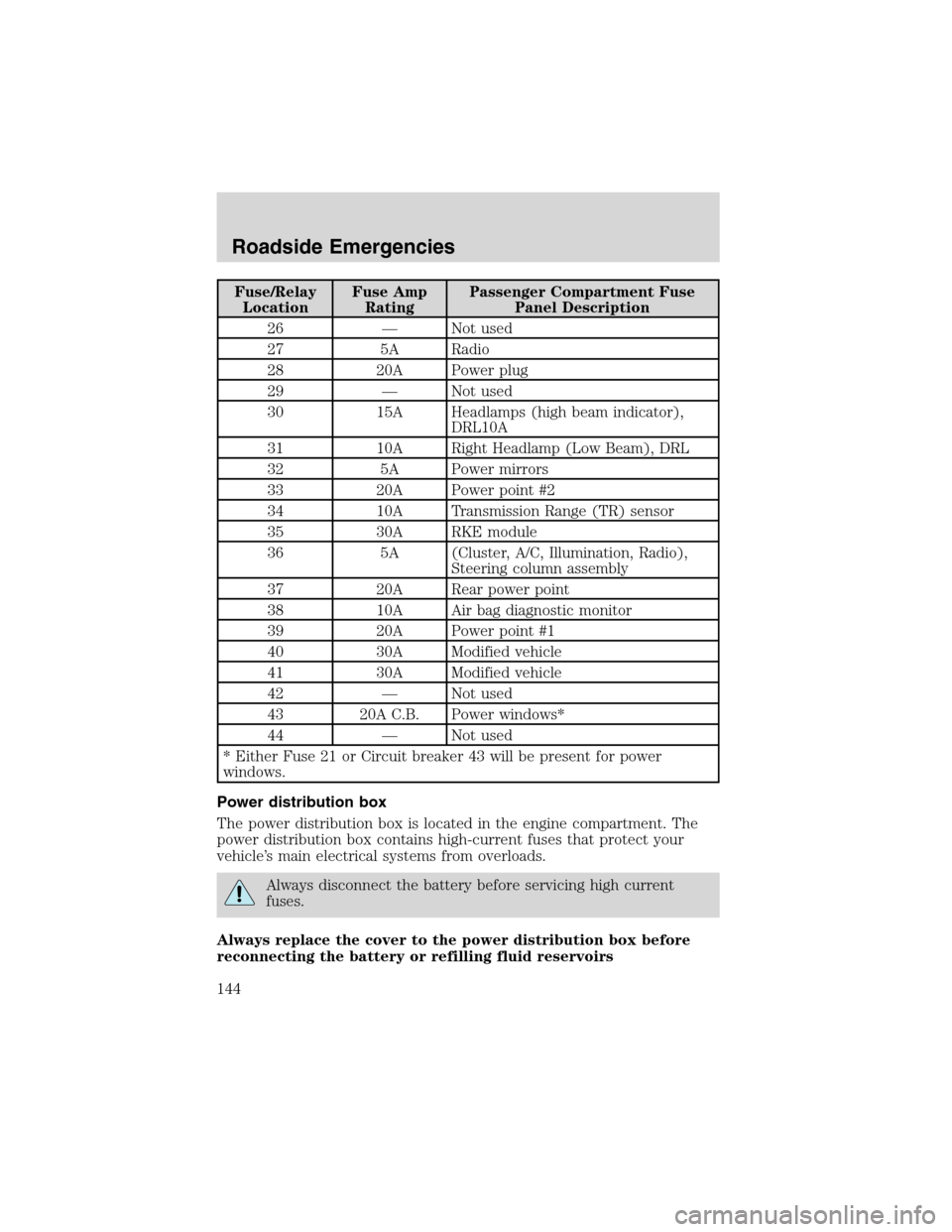
The fuses are coded as follows.
Fuse/Relay
LocationFuse Amp
RatingPassenger Compartment Fuse
Panel Description
1 20A 4WABS module
2 15A Brake warning lamp, Instrument
cluster, Warning chime, 4WABS relay,
Warning indicators, Low vacuum
warning switch (Diesel only)
3 15A Main light switch, RKE module,
Radio, Instrument illumination, VCP
and video screens, Overhead console
4 15A Power locks w/RKE, Illuminated
entry, Warning chime, Modified
vehicle, Main light switch, Courtesy
lamps
5 20A RKE module, Power lock switches,
Memory lock, Power locks with RKE
1234
5
7
689101142
43
44 13 12 14
15 16 17
19 18
2021 22 23
25 24
26 27 28 29
31 30 32 33 3435
37
3638 3940
41
Roadside Emergencies
142
Page 143 of 232
Fuse/Relay
LocationFuse Amp
RatingPassenger Compartment Fuse
Panel Description
6 10A Brake shift interlock, Speed control,
DRL module
7 10A Multi-function switch, Turn signals
8 30A Radio capacitor(s), Ignition coil, PCM
diode, PCM power relay, Fuel heater
(Diesel only), Glow plug relay (Diesel
only)
9 30A Wiper control module, Windshield
wiper motor
10 20A Main light switch, Park lamps, License
lamp (external lamps), Multi-function
switch (flash-to-pass)
11 15A Brake pressure switch, Multi-function
switch (hazards), Brake lamp switch,
Brake lamps
12 15A Transmission Range (TR) sensor,
Backup lamps, Auxiliary battery relay
13 15A Blend door actuator, A/C heater,
Function selector switch
14 5A Instrument cluster (air bag and
charge indicator)
15 5A Trailer battery charge relay
16 30A Power seats
17—Not used
18—Not used
19 10A Air bag diagnostic monitor
20 5A Overdrive cancel switch
21 30A Power windows*
22 15A Memory power radio, Rear seat
control unit, Video screen
23 20A Cigar lighter, Data Link Connector
(DLC)
24—Not used
25 10A Left headlamp (low beam)
Roadside Emergencies
143
Page 144 of 232
Fuse/Relay
LocationFuse Amp
RatingPassenger Compartment Fuse
Panel Description
26—Not used
27 5A Radio
28 20A Power plug
29—Not used
30 15A Headlamps (high beam indicator),
DRL10A
31 10A Right Headlamp (Low Beam), DRL
32 5A Power mirrors
33 20A Power point #2
34 10A Transmission Range (TR) sensor
35 30A RKE module
36 5A (Cluster, A/C, Illumination, Radio),
Steering column assembly
37 20A Rear power point
38 10A Air bag diagnostic monitor
39 20A Power point #1
40 30A Modified vehicle
41 30A Modified vehicle
42—Not used
43 20A C.B. Power windows*
44—Not used
* Either Fuse 21 or Circuit breaker 43 will be present for power
windows.
Power distribution box
The power distribution box is located in the engine compartment. The
power distribution box contains high-current fuses that protect your
vehicle’s main electrical systems from overloads.
Always disconnect the battery before servicing high current
fuses.
Always replace the cover to the power distribution box before
reconnecting the battery or refilling fluid reservoirs
Roadside Emergencies
144
Page 145 of 232
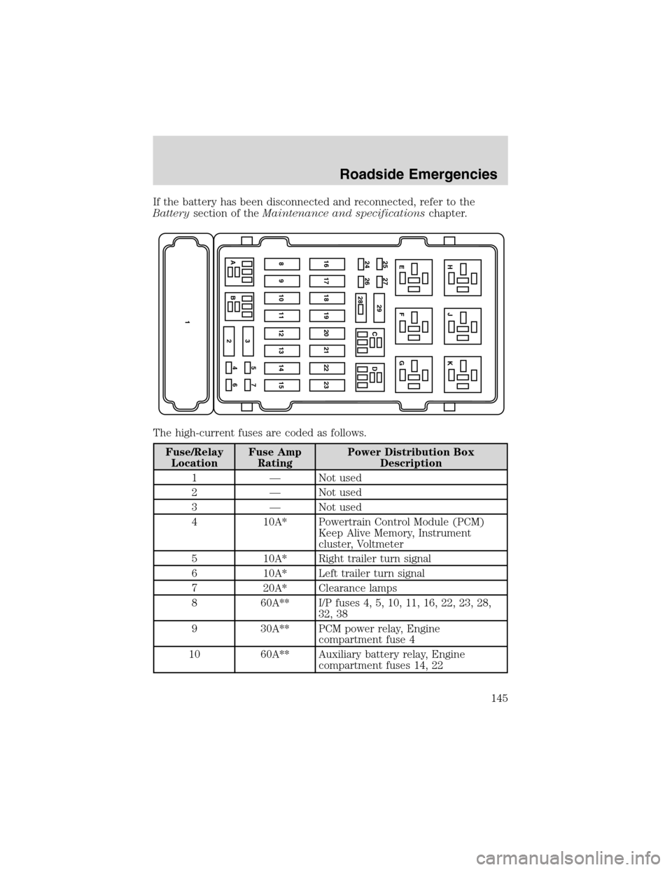
If the battery has been disconnected and reconnected, refer to the
Batterysection of theMaintenance and specificationschapter.
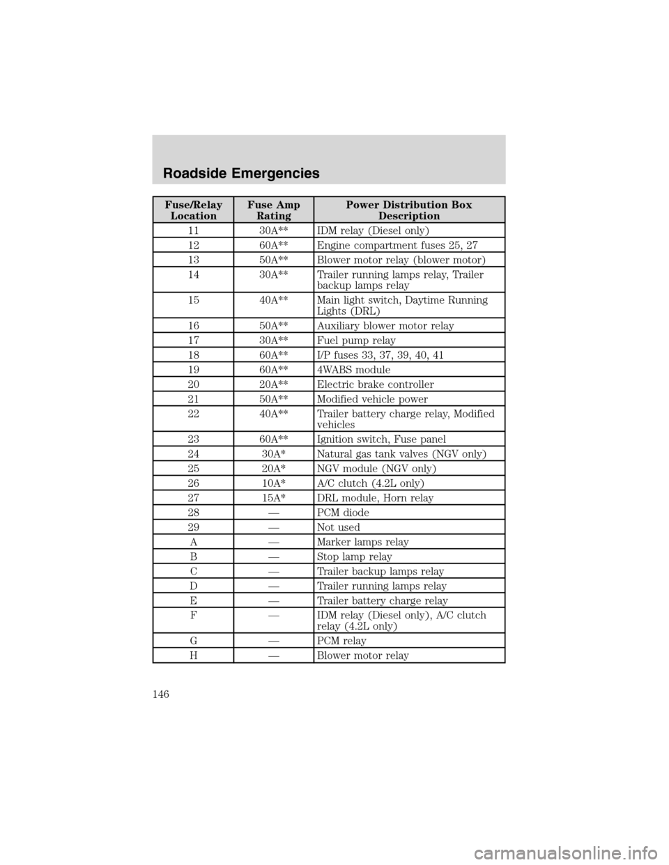
The high-current fuses are coded as follows.
Fuse/Relay
LocationFuse Amp
RatingPower Distribution Box
Description
1—Not used
2—Not used
3—Not used
4 10A* Powertrain Control Module (PCM)
Keep Alive Memory, Instrument
cluster, Voltmeter
5 10A* Right trailer turn signal
6 10A* Left trailer turn signal
7 20A* Clearance lamps
8 60A** I/P fuses 4, 5, 10, 11, 16, 22, 23, 28,
32, 38
9 30A** PCM power relay, Engine
compartment fuse 4
10 60A** Auxiliary battery relay, Engine
compartment fuses 14, 22
AB3
2
146 5715 14 13 12 11 10 9 823 22 21 20 19 18 17 1624 26 25 27
29
CDG F EK J H
28
Roadside Emergencies
145
Page 146 of 232
Fuse/Relay
LocationFuse Amp
RatingPower Distribution Box
Description
11 30A** IDM relay (Diesel only)
12 60A** Engine compartment fuses 25, 27
13 50A** Blower motor relay (blower motor)
14 30A** Trailer running lamps relay, Trailer
backup lamps relay
15 40A** Main light switch, Daytime Running
Lights (DRL)
16 50A** Auxiliary blower motor relay
17 30A** Fuel pump relay
18 60A** I/P fuses 33, 37, 39, 40, 41
19 60A** 4WABS module
20 20A** Electric brake controller
21 50A** Modified vehicle power
22 40A** Trailer battery charge relay, Modified
vehicles
23 60A** Ignition switch, Fuse panel
24 30A* Natural gas tank valves (NGV only)
25 20A* NGV module (NGV only)
26 10A* A/C clutch (4.2L only)
27 15A* DRL module, Horn relay
28—PCM diode
29—Not used
A—Marker lamps relay
B—Stop lamp relay
C—Trailer backup lamps relay
D—Trailer running lamps relay
E—Trailer battery charge relay
F—IDM relay (Diesel only), A/C clutch
relay (4.2L only)
G—PCM relay
H—Blower motor relay
Roadside Emergencies
146
Page 147 of 232
Fuse/Relay
LocationFuse Amp
RatingPower Distribution Box
Description
J—Horn relay
K—Fuel pump relay
* Mini fuses ** Maxi fuses
Relays
Relays are located in the power distribution box and should be replaced
by qualified technicians.
CHANGING A FLAT TIRE
If you get a flat tire while driving:
•do not brake heavily.
•gradually decrease the vehicle’s speed.
•hold the steering wheel firmly.
•slowly move to a safe place on the side of the road.
The use of tire sealants is not recommended and may
compromise the integrity of your tires. The use of tire sealants
may also affect your tire pressure monitoring system (if equipped).
Spare tire information
The spare tire for your vehicle is stowed under the rear of your vehicle
(except cutaway and stripped chassis models).
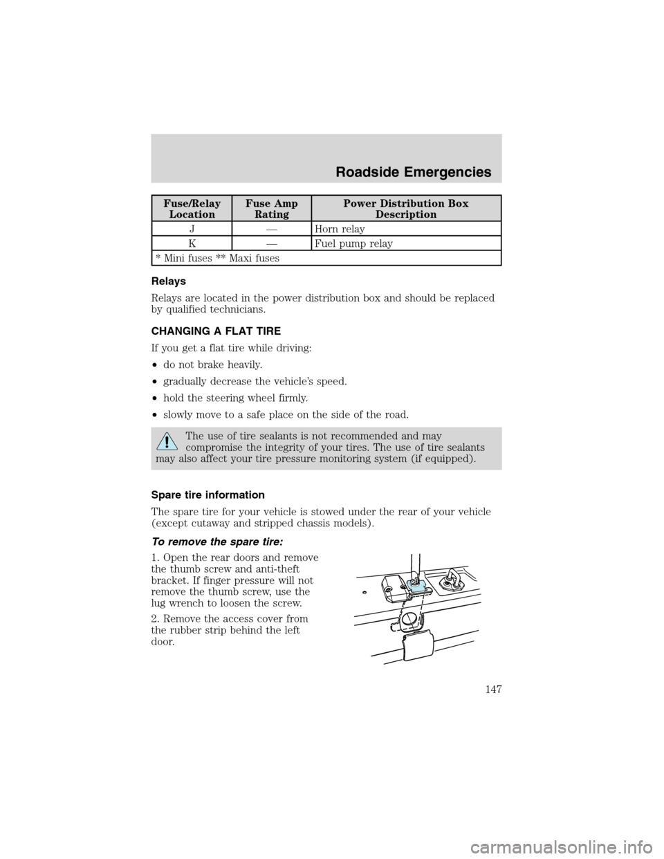
To remove the spare tire:
1. Open the rear doors and remove
the thumb screw and anti-theft
bracket. If finger pressure will not
remove the thumb screw, use the
lug wrench to loosen the screw.
2. Remove the access cover from
the rubber strip behind the left
door.
Roadside Emergencies
147
Page 230 of 232
L
Lamps
bulb replacement
specifications chart ..................55
cargo lamps ...............................54
daytime running light ...............53
headlamps .................................53
headlamps, flash to pass ..........54
instrument panel, dimming .....54
interior lamps ...........................55
replacing bulbs ...................55–60
Lane change indicator
(see Turn signal) ........................54
Lights, warning and indicator ....10
anti-lock brakes (ABS) ..........114
speed control ............................69
Load limits .................................122
GAWR ......................................122
GVWR ......................................122
trailer towing ..........................122
Loading instructions .................124
Lubricant specifications ...217, 220
Lumbar support, seats ...............76
M
Mirrors
fold away ...................................67
side view mirrors (power) .......66
Motorcraft parts ................198, 212
O
Octane rating ............................197
Oil (see Engine oil) ..................179
P
Parking brake ............................115Parts (see Motorcraft parts) ....212
Power distribution box (see
Fuses) ........................................144
Power door locks ........................71
Power point .................................65
Power steering ..........................115
fluid, checking and adding ....203
fluid, refill capacity ................213
fluid, specifications .........217, 220
Power Windows ...........................66
Preparing to drive your
vehicle ........................................116
R
Radio ..........................15, 17, 20, 24
Relays ................................140, 147
Remote entry system
illuminated entry ......................74
locking/unlocking doors ...........71
Roadside assistance ..................137
S
Safety belts (see Safety
restraints) ........................80, 82–85
Safety defects, reporting ..........169
Safety restraints ..............80, 82–85
belt minder ...............................86
cleaning the safety belts ..........90
extension assembly ..................90
for adults .............................82–84
for children .........................95–96
lap belt ......................................85
warning light and chime ..........86
Safety seats for children ............99
Seat belts (see Safety
restraints) ....................................80
Index
230