ECO mode FORD E SERIES 2006 4.G Owner's Manual
[x] Cancel search | Manufacturer: FORD, Model Year: 2006, Model line: E SERIES, Model: FORD E SERIES 2006 4.GPages: 248, PDF Size: 2.54 MB
Page 151 of 248
transmission is in the D (Overdrive) position; this engine braking will
slow the vehicle and assist the driver in controlling the vehicle when
descending a grade. Depending on driving conditions and load
conditions, the transmission may downshift, slow the vehicle and control
the vehicle speed when descending a hill, without the accelerator pedal
being pressed. The amount of downshift braking provided will vary based
upon the amount the brake pedal is depressed.
To deactivate the Tow/Haul feature and return to normal driving mode,
press the button on the end of the gearshift lever. The TOW HAUL light
will no longer be illuminated.
When you shut-off and restart the engine, the transmission will
automatically return to normal D (Overdrive) mode (Tow/Haul OFF).
Do not use the Tow/Haul feature when driving in icy or slippery
conditions as the increased engine braking can cause the rear
wheels to slide and the vehicle to swing around with the possible loss
of vehicle control..
3 (Third)
Transmission starts and holds third gear only.
Used for improved traction on slippery roads. Selecting 3 (Third)
provides engine braking.
2 (Second)
Use 2 (Second) to start-up on slippery roads or to provide additional
engine braking on downgrades.
1 (First)
•Provides maximum engine braking.
•Allows upshifts by moving gearshift lever.
•The transmission will not downshift into 1 (First) at high speeds; it
will downshift to a lower gear and then shift into 1 (First) when the
vehicle reaches slower speeds.
Forced downshifts
•Allowed in
(Overdrive) or Drive.
•Depress the accelerator to the floor.
•Allows transmission to select an appropriate gear.
2006 Econoline(eco)
Owners Guide (post-2002-fmt)
USA(fus)
Driving
151
Page 169 of 248
Spare tire information
The spare tire for your vehicle is stowed under the rear of your vehicle
(except cutaway and stripped chassis models).
To remove the spare tire:
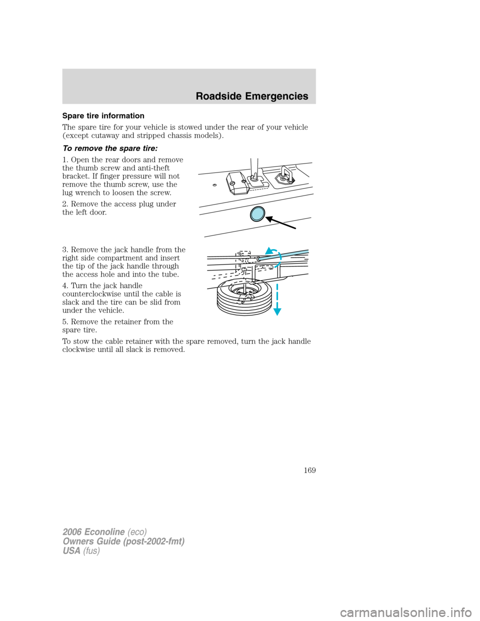
1. Open the rear doors and remove
the thumb screw and anti-theft
bracket. If finger pressure will not
remove the thumb screw, use the
lug wrench to loosen the screw.
2. Remove the access plug under
the left door.
3. Remove the jack handle from the
right side compartment and insert
the tip of the jack handle through
the access hole and into the tube.
4. Turn the jack handle
counterclockwise until the cable is
slack and the tire can be slid from
under the vehicle.
5. Remove the retainer from the
spare tire.
To stow the cable retainer with the spare removed, turn the jack handle
clockwise until all slack is removed.
2006 Econoline(eco)
Owners Guide (post-2002-fmt)
USA(fus)
Roadside Emergencies
169
Page 172 of 248
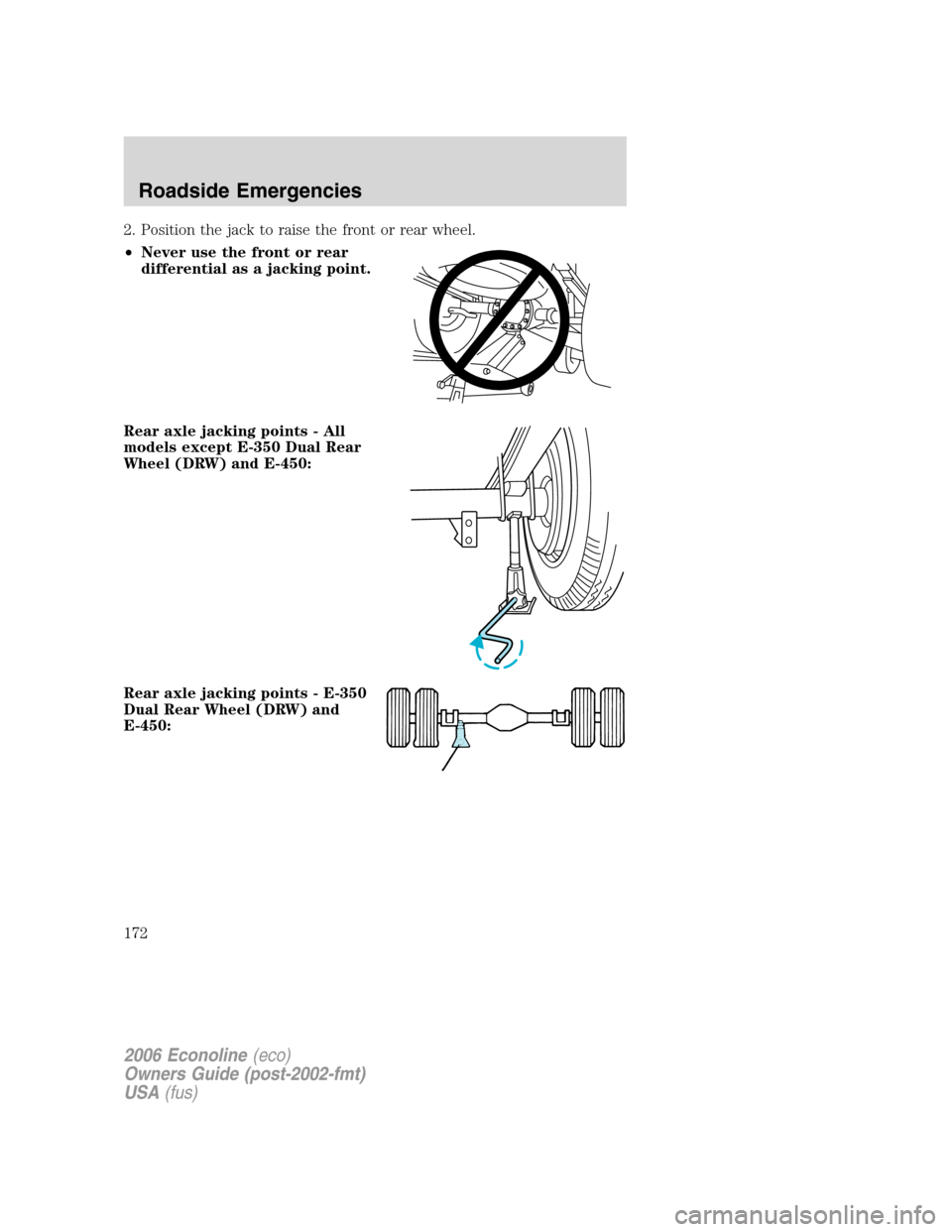
2. Position the jack to raise the front or rear wheel.
•Never use the front or rear
differential as a jacking point.
Rear axle jacking points - All
models except E-350 Dual Rear
Wheel (DRW) and E-450:
Rear axle jacking points - E-350
Dual Rear Wheel (DRW) and
E-450:
2006 Econoline(eco)
Owners Guide (post-2002-fmt)
USA(fus)
Roadside Emergencies
172
Page 178 of 248
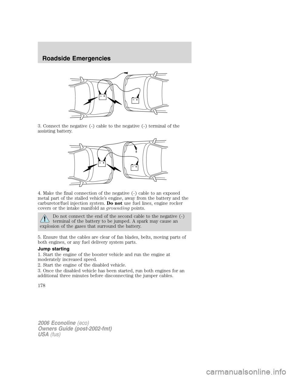
3. Connect the negative (-) cable to the negative (-) terminal of the
assisting battery.
4. Make the final connection of the negative (-) cable to an exposed
metal part of the stalled vehicle’s engine, away from the battery and the
carburetor/fuel injection system.Do notuse fuel lines, engine rocker
covers or the intake manifold asgroundingpoints.
Do not connect the end of the second cable to the negative (-)
terminal of the battery to be jumped. A spark may cause an
explosion of the gases that surround the battery.
5. Ensure that the cables are clear of fan blades, belts, moving parts of
both engines, or any fuel delivery system parts.
Jump starting
1. Start the engine of the booster vehicle and run the engine at
moderately increased speed.
2. Start the engine of the disabled vehicle.
3. Once the disabled vehicle has been started, run both engines for an
additional three minutes before disconnecting the jumper cables.
+–+–
+–+–
2006 Econoline(eco)
Owners Guide (post-2002-fmt)
USA(fus)
Roadside Emergencies
178
Page 186 of 248
Board membership
The Board consists of:
•Three consumer representatives
•A Ford or Lincoln Mercury dealership representative
Consumer candidates for Board membership are recruited and trained by
an independent consulting firm. The dealership Board member is chosen
from Ford and Lincoln Mercury dealership management, recognized for
their business leadership qualities.
What the Board needs
To have your case reviewed you must complete the application in the
DSB brochure and mail it to the address provided on the application
form. Some states will require you to use certified mail, with return
receipt requested.
Your application is reviewed and, if it is determined to be eligible, you
will receive an acknowledgment indicating:
•The file number assigned to your application.
•The toll-free phone number of the DSB’s independent administrator.
Your dealership and a Ford Motor Company representative will then be
asked to submit statements.
To properly review your case, the Board needs the following information:
•Legible copies of all documents and maintenance or repair orders
relevant to the case.
•The year, make, model, and Vehicle Identification Number (VIN) listed
on your vehicle ownership license.
•The date of repair(s) and mileage at the time of occurrence(s).
•The current mileage.
•The name of the dealer(s) who sold or serviced the vehicle.
•A brief description of your unresolved concern.
•A brief summary of the action taken by the dealer(s) and Ford Motor
Company.
•The names (if known) of all the people you contacted at the
dealership(s).
•A description of the action you expect to resolve your concern.
You will receive a letter of explanation if your application does not
qualify for Board review.
2006 Econoline(eco)
Owners Guide (post-2002-fmt)
USA(fus)
Customer Assistance
186
Page 211 of 248
What you should know about fail-safe cooling (if equipped)
If the engine coolant supply is depleted, this feature allows the vehicle to
be driven temporarily before incremental component damage is incurred.
The “fail-safe” distance depends on ambient temperatures, vehicle load
and terrain.
How fail-safe cooling works
If the engine begins to overheat:
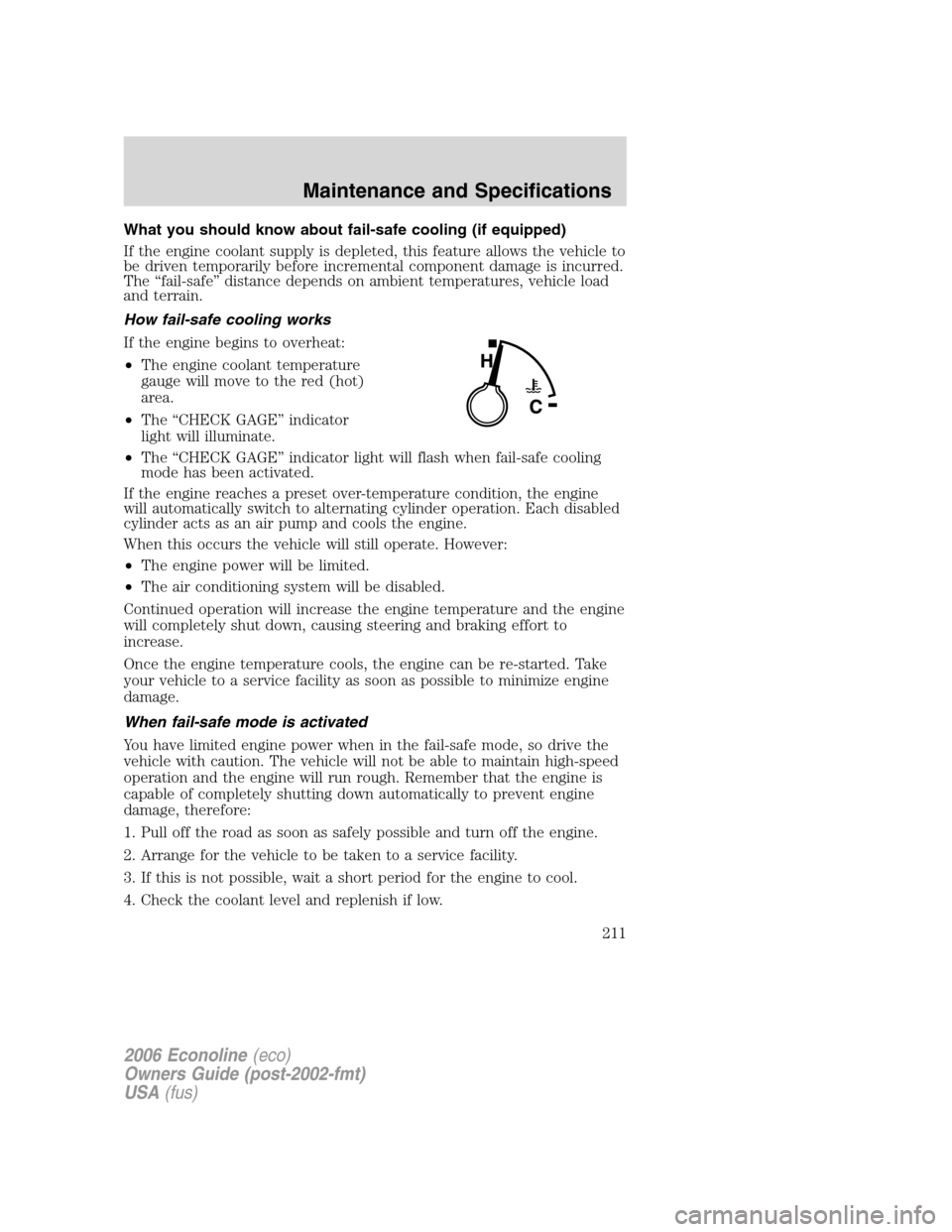
•The engine coolant temperature
gauge will move to the red (hot)
area.
•The “CHECK GAGE” indicator
light will illuminate.
•The “CHECK GAGE” indicator light will flash when fail-safe cooling
mode has been activated.
If the engine reaches a preset over-temperature condition, the engine
will automatically switch to alternating cylinder operation. Each disabled
cylinder acts as an air pump and cools the engine.
When this occurs the vehicle will still operate. However:
•The engine power will be limited.
•The air conditioning system will be disabled.
Continued operation will increase the engine temperature and the engine
will completely shut down, causing steering and braking effort to
increase.
Once the engine temperature cools, the engine can be re-started. Take
your vehicle to a service facility as soon as possible to minimize engine
damage.
When fail-safe mode is activated
You have limited engine power when in the fail-safe mode, so drive the
vehicle with caution. The vehicle will not be able to maintain high-speed
operation and the engine will run rough. Remember that the engine is
capable of completely shutting down automatically to prevent engine
damage, therefore:
1. Pull off the road as soon as safely possible and turn off the engine.
2. Arrange for the vehicle to be taken to a service facility.
3. If this is not possible, wait a short period for the engine to cool.
4. Check the coolant level and replenish if low.
2006 Econoline(eco)
Owners Guide (post-2002-fmt)
USA(fus)
Maintenance and Specifications
211
Page 218 of 248
•Always use fuel with the recommended octane rating.
•Use a known quality gasoline, preferably a national brand.
•Use the same side of the same pump and have the vehicle facing the
same direction each time you fill up.
•Have the vehicle loading and distribution the same every time.
Your results will be most accurate if your filling method is consistent.
Calculating fuel economy
1. Fill the fuel tank completely and record the initial odometer reading
(in miles or kilometers).
2. Each time you fill the tank, record the amount of fuel added (in
gallons or liters).
3. After at least three to five tank fill-ups, fill the fuel tank and record
the current odometer reading.
4. Subtract your initial odometer reading from the current odometer
reading.
5. Follow one of the simple calculations in order to determine fuel economy:
Calculation 1:Divide total miles traveled by total gallons used.
Calculation 2:Multiply liters used by 100, then divide by total
kilometers traveled.
Keep a record for at least one month and record the type of driving (city
or highway). This will provide an accurate estimate of the vehicle’s fuel
economy under current driving conditions. Additionally, keeping records
during summer and winter will show how temperature impacts fuel
economy. In general, lower temperatures give lower fuel economy.
Driving style — good driving and fuel economy habits
Give consideration to the lists that follow and you may be able to change
a number of variables and improve your fuel economy.
Habits
•Smooth, moderate operation can yield up to 10% savings in fuel.
•Steady speeds without stopping will usually give the best fuel
economy.
•
Idling for long periods of time (greater than one minute) may waste fuel.
•Anticipate stopping; slowing down may eliminate the need to stop.
•Sudden or hard accelerations may reduce fuel economy.
2006 Econoline(eco)
Owners Guide (post-2002-fmt)
USA(fus)
Maintenance and Specifications
218
Page 237 of 248
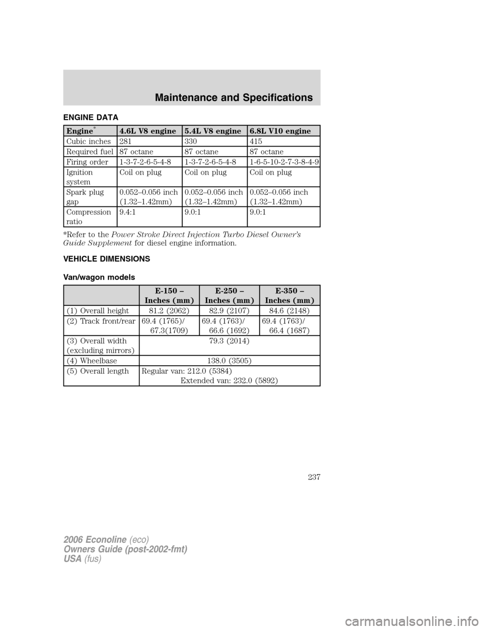
ENGINE DATA
Engine*4.6L V8 engine 5.4L V8 engine 6.8L V10 engine
Cubic inches 281 330 415
Required fuel 87 octane 87 octane 87 octane
Firing order 1-3-7-2-6-5-4-8 1-3-7-2-6-5-4-8 1-6-5-10-2-7-3-8-4-9
Ignition
systemCoilonplug Coilonplug Coilonplug
Spark plug
gap0.052–0.056 inch
(1.32–1.42mm)0.052–0.056 inch
(1.32–1.42mm)0.052–0.056 inch
(1.32–1.42mm)
Compression
ratio9.4:1 9.0:1 9.0:1
*Refer to thePower Stroke Direct Injection Turbo Diesel Owner’s
Guide Supplementfor diesel engine information.
VEHICLE DIMENSIONS
Van/wagon models
E-150 –
Inches (mm)E-250 –
Inches (mm)E-350 –
Inches (mm)
(1) Overall height 81.2 (2062) 82.9 (2107) 84.6 (2148)
(2) Track front/rear 69.4 (1765)/
67.3(1709)69.4 (1763)/
66.6 (1692)69.4 (1763)/
66.4 (1687)
(3) Overall width
(excluding mirrors)79.3 (2014)
(4) Wheelbase 138.0 (3505)
(5) Overall length Regular van: 212.0 (5384)
Extended van: 232.0 (5892)
2006 Econoline(eco)
Owners Guide (post-2002-fmt)
USA(fus)
Maintenance and Specifications
237
Page 239 of 248
Cutaway/commercial stripped chassis models
E-350 – inches (mm) E-450 – inches (mm)
(1) Overall height Refer to Body Builder for specifications.
(2) Track front/rearCutaway:
69.4 (1763)
SRW: 72.1 (1831)
DRW: 73.2 (1860)
Stripped Chassis:
69.4 (1763)
SRW: 72.1 (1831.4)
DRW: 73.2 (1859)69.4 (1763)/
77.7 (1974)
(3) Overall width Refer to Body Builder for specifications.
(4) Wheelbase 138.0 (3505)
158.0 (4012.3)
176.0 (4470)158.0 (4012.3)
176.0 (4470)
(5) Overall length Refer to Body Builder for specifications.
VEHICLE IDENTIFICATION NUMBER
Complete Ford built vehicles
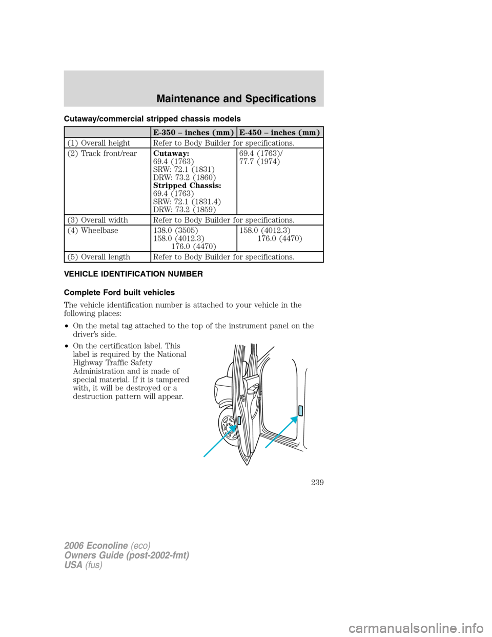
The vehicle identification number is attached to your vehicle in the
following places:
•On the metal tag attached to the top of the instrument panel on the
driver’s side.
•On the certification label. This
label is required by the National
Highway Traffic Safety
Administration and is made of
special material. If it is tampered
with, it will be destroyed or a
destruction pattern will appear.
2006 Econoline(eco)
Owners Guide (post-2002-fmt)
USA(fus)
Maintenance and Specifications
239
Page 241 of 248
GENUINE FORD ACCESSORIES FOR YOUR VEHICLE
A wide selection of Genuine Ford Accessories are available for your
vehicle through your local authorized Ford or Ford of Canada dealer.
These quality accessories have been specifically engineered to fulfill your
automotive needs; they are custom designed to complement the style
and aerodynamic appearance of your vehicle. In addition, each accessory
is made from high quality materials and meets or exceeds Ford’s rigorous
engineering and safety specifications. Ford Motor Company will repair or
replace any properly dealer-installed Genuine Ford Accessory found to
be defective in factory-supplied materials or workmanship during the
warranty period, as well as any component damaged by the defective
accessory. The accessory will be warranted for whichever provides you
the greatest benefit:
•12 months or 12,000 miles (20,000 km) (whichever occurs first), or
•the remainder of your new vehicle limited warranty.
This means that Genuine Ford Accessories purchased along with your
new vehicle and installed by the dealer are covered for the full length of
your New Vehicle’s Limited Warranty — 3 years or 36,000 miles (60,000
km) (whichever occurs first). Contact your dealer for details and a copy
of the warranty.
Not all accessories are available for all models.
The following is a list of several Genuine Ford Accessory products. Not
all accessories are available for all models. For a complete listing of the
accessories that are available for your vehicle, please contact your dealer
or visit our online store at: www.fordaccessoriesstore.com.
Exterior style
Bug shields
Deflectors
Daytime Running Lamps (DRLs)
Splash guards
Step bars
Interior style
Electrochromatic compass/temperature interior mirrors
Floor mats
Speed control
2006 Econoline(eco)
Owners Guide (post-2002-fmt)
USA(fus)
Accessories
241