stop start FORD E SERIES 2022 User Guide
[x] Cancel search | Manufacturer: FORD, Model Year: 2022, Model line: E SERIES, Model: FORD E SERIES 2022Pages: 300, PDF Size: 3.18 MB
Page 93 of 300
Fuel Filler Cap
WARNING: The fuel system may
be under pressure. If you hear a hissing
sound near the fuel filler inlet, do not
refuel until the sound stops. Otherwise,
fuel may spray out, which could cause
serious personal injury.
Note: If you must replace the fuel filler cap,
replace it with a fuel filler cap that is
designed for your vehicle. The customer
warranty may be void for any damage to the
fuel tank or fuel system if the correct
genuine Ford, Motorcraft or other certified
fuel filler cap is not used.
Your vehicle has a threaded fuel filler cap.
When fueling your vehicle:
1. Put your vehicle in park (P).
2. Switch the engine off.
3. Carefully turn the filler cap counterclockwise until it spins off.
4. Pull to remove the cap from the fuel filler pipe and place on the fuel door
hanging hook if equipped.
5. To install the fuel filler cap, hold the cap by the cover handle and place the
threaded end of the cap into filler pipe.
Turn the cap clockwise until it clicks at
least once.
If the Check Fuel Cap light or a Check Fuel
Cap message appears in the instrument
cluster and stays on after you start the
engine, you may not have installed the fuel
filler properly. If the fuel cap light remains on, at the next
opportunity, safely pull off of the road,
remove the fuel filler cap, align the cap
properly and reinstall it. The check fuel cap
light or Check fuel cap message may not
reset immediately. It may take several
driving cycles for the indicators to turn off.
A driving cycle consists of an engine
start-up (after four or more hours with the
engine off) followed by normal city and
highway driving.
FUEL CONSUMPTION
Advertised Capacity
The advertised capacity is the maximum
amount of fuel that you can add to the fuel
tank after running out of fuel. Included in
the advertised capacity is an empty
reserve. The empty reserve is an
unspecified amount of fuel that remains
in the fuel tank when the fuel gauge
indicates empty.
Note:
The amount of fuel in the empty
reserve varies and should not be relied upon
to increase driving range.
Fuel Economy
Your vehicle calculates fuel economy
figures through the trip computer average
fuel function. See
General Information
(page 65).
The first
1,000 mi (1,500 km) of driving is
the break-in period of the engine. A more
accurate measurement is obtained after
2,000 mi (3,000 km)
.
Impacting Fuel Economy
• Incorrect tire inflation pressures.
• Fully loading your vehicle.
• Carrying unnecessary weight.
90
E-Series (TE4) Canada/United States of America, enUSA, Edition date: 202010, First-Printing Fuel and Refueling
Page 98 of 300
Your vehicle may not pass the I/M test if
the service engine soon indicator is on or
not working properly (bulb is burned out),
or if the OBD-II system has determined
that some of the emission control systems
have not been properly checked. In this
case, the vehicle is not ready for I/M
testing.
If the vehicle
’s engine or transmission has
just been serviced, or the battery has
recently run down or been replaced, the
OBD-II system may indicate that the
vehicle is not ready for I/M testing. To
determine if the vehicle is ready for I/M
testing, turn the ignition key to the on
position for 15 seconds without cranking
the engine. If the service engine soon
indicator blinks eight times, it means that
the vehicle is not ready for I/M testing; if
the service engine soon indicator stays on
solid, it means that your vehicle is ready
for I/M testing.
The OBD-II system checks the emission
control system during normal driving. A
complete check may take several days.
If the vehicle is not ready for I/M testing,
you can perform the following driving cycle
consisting of mixed city and highway
driving:
1. 15 minutes of steady driving on an expressway or highway followed by 20
minutes of stop-and-go driving with at
least four 30-second idle periods.
2. Allow your vehicle to sit for at least eight hours with the ignition off. Then,
start the vehicle and complete the
above driving cycle. The vehicle must
warm up to its normal operating
temperature. Once started, do not turn
off the vehicle until the above driving
cycle is complete.
If the vehicle is still not ready for I/M
testing, you need to repeat the above
driving cycle.
95
E-Series (TE4) Canada/United States of America, enUSA, Edition date: 202010, First-Printing Engine Emission Control
Page 99 of 300
AUTOMATIC TRANSMISSION
WARNING: Apply the parking
brake, shift into park (P), switch the
ignition off and remove the key before
you leave your vehicle. Failure to follow
this instruction could result in personal
injury or death. Putting your vehicle in or out of
gear:
1. Fully press down the brake pedal.
2. Move the gearshift lever into the
preferred gear.
3. When you finish driving, come to a complete stop.
4. Move the gearshift lever and securely latch it in park (P).
5. Release the brake pedal and the transmission remains in the selected
gear.
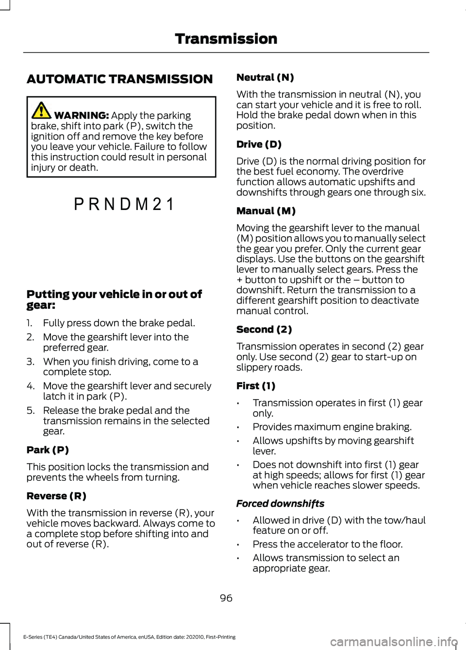
Park (P)
This position locks the transmission and
prevents the wheels from turning.
Reverse (R)
With the transmission in reverse (R), your
vehicle moves backward. Always come to
a complete stop before shifting into and
out of reverse (R). Neutral (N)
With the transmission in neutral (N), you
can start your vehicle and it is free to roll.
Hold the brake pedal down when in this
position.
Drive (D)
Drive (D) is the normal driving position for
the best fuel economy. The overdrive
function allows automatic upshifts and
downshifts through gears one through six.
Manual (M)
Moving the gearshift lever to the manual
(M) position allows you to manually select
the gear you prefer. Only the current gear
displays. Use the buttons on the gearshift
lever to manually select gears. Press the
+ button to upshift or the – button to
downshift. Return the transmission to a
different gearshift position to deactivate
manual control.
Second (2)
Transmission operates in second (2) gear
only. Use second (2) gear to start-up on
slippery roads.
First (1)
•
Transmission operates in first (1) gear
only.
• Provides maximum engine braking.
• Allows upshifts by moving gearshift
lever.
• Does not downshift into first (1) gear
at high speeds; allows for first (1) gear
when vehicle reaches slower speeds.
Forced downshifts
• Allowed in drive (D) with the tow/haul
feature on or off.
• Press the accelerator to the floor.
• Allows transmission to select an
appropriate gear.
96
E-Series (TE4) Canada/United States of America, enUSA, Edition date: 202010, First-Printing TransmissionP R N D M 2 1E307627
Page 102 of 300
If the fuse is not blown and the brake
lamps are working properly, the following
procedure allows you to move the gearshift
lever from park (P):
1. Apply the parking brake. Switch the
ignition key to 1 (off), then remove the
key.
2. Move the steering column to the full down and full rearward position,
toward the driver seat.
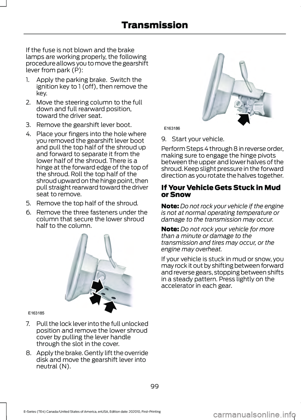
3. Remove the gearshift lever boot.
4. Place your fingers into the hole where you removed the gearshift lever boot
and pull the top half of the shroud up
and forward to separate it from the
lower half of the shroud. There is a
hinge at the forward edge of the top of
the shroud. Roll the top half of the
shroud upward on the hinge point, then
pull straight rearward toward the driver
seat to remove.
5. Remove the top half of the shroud.
6. Remove the three fasteners under the column that secure the lower shroud
half to the column. 7.
Pull the lock lever into the full unlocked
position and remove the lower shroud
cover by pulling the lever handle
through the slot in the cover.
8. Apply the brake. Gently lift the override
disk and move the gearshift lever into
neutral (N). 9. Start your vehicle.
Perform Steps 4 through 8 in reverse order,
making sure to engage the hinge pivots
between the upper and lower halves of the
shroud. Keep slight pressure in the forward
direction as you rotate the halves together.
If Your Vehicle Gets Stuck in Mud
or Snow
Note:
Do not rock your vehicle if the engine
is not at normal operating temperature or
damage to the transmission may occur.
Note: Do not rock your vehicle for more
than a minute or damage to the
transmission and tires may occur, or the
engine may overheat.
If your vehicle is stuck in mud or snow, you
may rock it out by shifting between forward
and reverse gears, stopping between shifts
in a steady pattern. Press lightly on the
accelerator in each gear.
99
E-Series (TE4) Canada/United States of America, enUSA, Edition date: 202010, First-Printing TransmissionE163185 E163186
Page 140 of 300
•
Stop lamps: Using the manual control
lever illuminates both the trailer brake
lamps and your vehicle brake lamps
except the center high-mount stop
lamp, if you make the proper electrical
connection to the trailer. Pressing your
vehicle brake pedal also illuminates
both trailer and vehicle brake lamps.
Procedure for Adjusting Gain
Note: Only perform this procedure in a
traffic-free environment at speeds of
approximately 20-25 mph (30-40 km/h).
The gain setting sets the trailer brake
controller for the specific towing condition.
You should change the setting as towing
conditions change. Changes to towing
conditions include trailer load, vehicle load,
road conditions and weather.
The gain should be set to provide the
maximum trailer braking assistance while
making sure the trailer wheels do not lock
when using the brakes. Locked trailer
wheels may lead to trailer instability.
1. Make sure the trailer brakes are in good
working condition, functioning normally
and properly adjusted. See your trailer
dealer if necessary.
2. Hook up the trailer and make the electrical connections according to the
trailer manufacturer's instructions.
3. When you plug in a trailer with electric or electric-over-hydraulic brakes, a
message confirming connection
appears in the information display.
4. Use the gain adjustment (+ and -) buttons to increase or decrease the
gain setting to the desired starting
point. A gain setting of 6.0 is a good
starting point for heavier loads.
5. In a traffic-free environment, tow the trailer on a dry, level surface at a speed
of 20-25 mph (30-40 km/h) and
squeeze the manual control lever
completely. 6. If the trailer wheels lock up, indicated
by squealing tires, reduce the gain
setting. If the trailer wheels turn freely,
increase the gain setting. Repeat Steps
5 and 6 until the gain setting is at a
point just below trailer wheel lock-up.
If towing a heavier trailer, trailer wheel
lock-up may not be attainable even
with the maximum gain setting of 10.
Explanation of Information Display
Warning Messages
Note: An authorized dealer can diagnose
the trailer brake controller to determine
exactly which trailer fault has occurred.
However, your Ford warranty does not cover
this diagnosis if the fault is with the trailer.
A message indicating a trailer brake
module fault may display in response to
faults sensed by the trailer brake controller,
accompanied by a single tone. If this
message appears, contact an authorized
dealer as soon as possible for diagnosis
and repair. The controller may still
function, but performance may be
degraded.
A message indicating a trailer wiring fault
may display when there is a short circuit
on the electric brake output wire. If this
message displays, accompanied by a
single tone, with no trailer connected, the
problem is with your vehicle wiring
between the trailer brake controller and
the 7-pin connector at the bumper. If the
message only displays with a trailer
connected, the problem is with the trailer
wiring. Consult your trailer dealer for
assistance. This can be a short to ground
(such as a chaffed wire), short to voltage
(such as a pulled pin on trailer emergency
breakaway battery) or the trailer brakes
may be drawing too much current.
137
E-Series (TE4) Canada/United States of America, enUSA, Edition date: 202010, First-Printing Towing
Page 141 of 300
Points to Remember
Note:
Do not attempt removal of the trailer
brake controller without consulting the
Workshop Manual. Damage to the unit may
result.
• Adjust gain setting before using the
trailer brake controller for the first time.
• Adjust gain setting, using the procedure
above, whenever road, weather and
trailer or vehicle loading conditions
change from when the gain was initially
set.
• Only use the manual control lever for
proper adjustment of the gain during
trailer setup. Misuse, such as
application during trailer sway, could
cause instability of trailer or tow
vehicle.
• Avoid towing in adverse weather
conditions. The trailer brake controller
does not provide anti-lock control of
the trailer wheels. Trailer wheels can
lock up on slippery surfaces, resulting
in reduced stability of trailer and tow
vehicle.
• The trailer brake controller is equipped
with a feature that reduces output at
vehicle speeds below 11 mph (18 km/h)
so trailer and vehicle braking is not jerky
or harsh. This feature is only available
when applying the brakes using your
vehicle's brake pedal, not the
controller.
• The controller interacts with the brake
control system and powertrain control
system of your vehicle to provide the
best performance on different road
conditions.
• Your vehicle's brake system and the
trailer brake system work
independently of each other. Changing
the gain setting on the controller does
not affect the operation of your
vehicle's brakes whether you attach a
trailer or not. •
When you switch the engine off, the
controller output is disabled and the
display and module shut down. The
controller module and display turn on
when you switch the ignition on.
• The trailer brake controller is only a
factory-installed or dealer-installed
item. Ford is not responsible for
warranty or performance of the
controller due to misuse or customer
installation.
Trailer Lamps WARNING: Never connect any
trailer lamp wiring to the vehicle's tail
lamp wiring; this may damage the
electrical system resulting in fire. Contact
your authorized dealer as soon as
possible for assistance in proper trailer
tow wiring installation. Additional
electrical equipment may be required.
Trailer lamps are required on most towed
vehicles. Make sure all running lights, brake
lights, direction indicators and hazard lights
are working.
Before Towing a Trailer
Practice turning, stopping and backing up
to get the feel of your vehicle-trailer
combination before starting on a trip.
When turning, make wider turns so the
trailer wheels clear curbs and other
obstacles.
When Towing a Trailer
• Do not drive faster than
70 mph
(113 km/h) during the first 500 mi
(800 km).
• Do not make full-throttle starts.
• Check your hitch, electrical connections
and trailer wheel lug nuts thoroughly
after you have traveled 50 mi (80 km).
138
E-Series (TE4) Canada/United States of America, enUSA, Edition date: 202010, First-Printing Towing
Page 148 of 300
Vehicles Sold in Canada: Getting
Roadside Assistance
To fully assist you should you have a
vehicle concern, Ford Motor Company of
Canada, Limited offers a complimentary
roadside assistance program. This program
is eligible within Canada or the continental
United States.
The service is available 24 hours a day,
seven days a week.
This program is separate from the New
Vehicle Limited Warranty, but the coverage
is concurrent with the powertrain coverage
period of your vehicle. Canadian roadside
coverage and benefits may differ from the
U.S. coverage.
If you require more information, please call
us in Canada at 1-800-665-2006, or visit
our website at www.ford.ca.
HAZARD FLASHERS
Note:
If used when the vehicle is not
running, the battery loses charge. As a result,
there may be insufficient power to restart
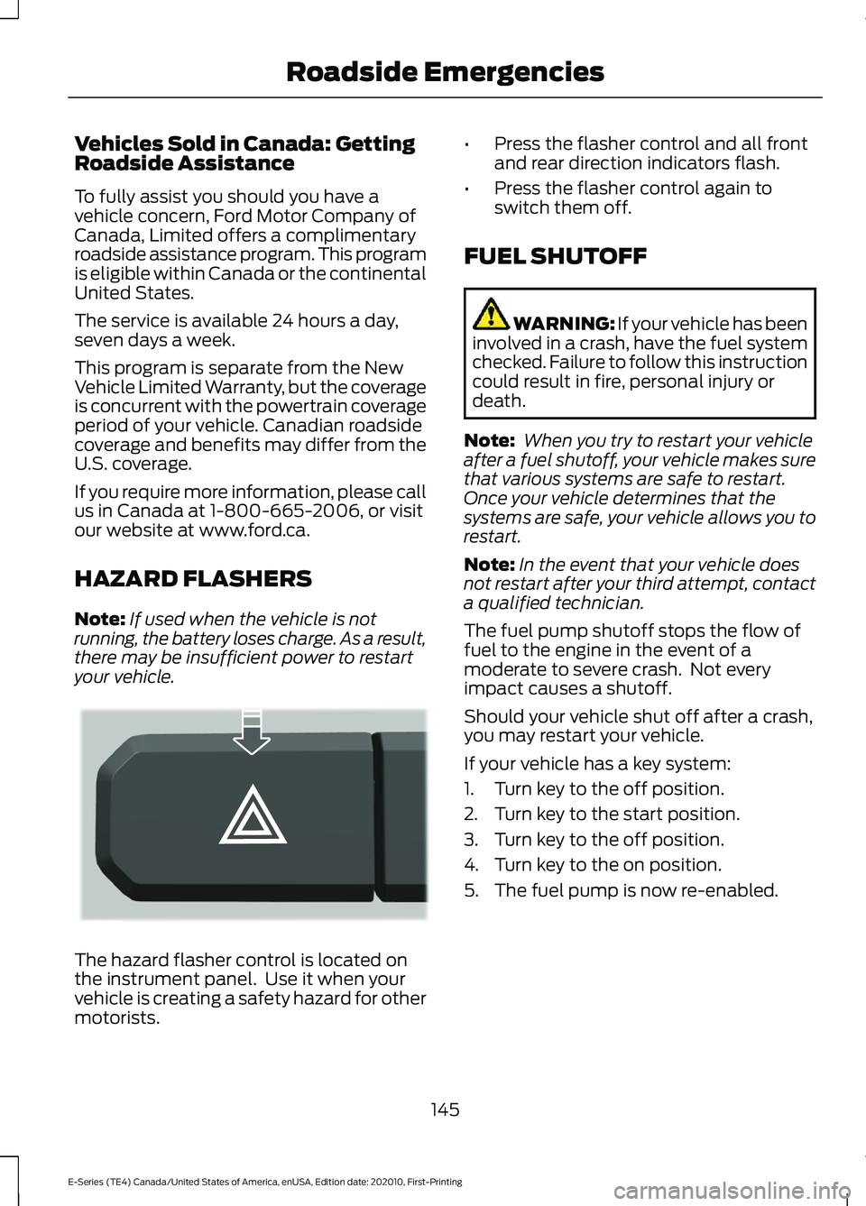
your vehicle. The hazard flasher control is located on
the instrument panel. Use it when your
vehicle is creating a safety hazard for other
motorists. •
Press the flasher control and all front
and rear direction indicators flash.
• Press the flasher control again to
switch them off.
FUEL SHUTOFF WARNING: If your vehicle has been
involved in a crash, have the fuel system
checked. Failure to follow this instruction
could result in fire, personal injury or
death.
Note: When you try to restart your vehicle
after a fuel shutoff, your vehicle makes sure
that various systems are safe to restart.
Once your vehicle determines that the
systems are safe, your vehicle allows you to
restart.
Note: In the event that your vehicle does
not restart after your third attempt, contact
a qualified technician.
The fuel pump shutoff stops the flow of
fuel to the engine in the event of a
moderate to severe crash. Not every
impact causes a shutoff.
Should your vehicle shut off after a crash,
you may restart your vehicle.
If your vehicle has a key system:
1. Turn key to the off position.
2. Turn key to the start position.
3. Turn key to the off position.
4. Turn key to the on position.
5. The fuel pump is now re-enabled.
145
E-Series (TE4) Canada/United States of America, enUSA, Edition date: 202010, First-Printing Roadside EmergenciesE304635
Page 171 of 300
If it illuminates when the engine is running
this indicates a malfunction. Stop your
vehicle as soon as it is safe to do so and
switch the engine off. Check the engine oil
level. If the oil level is sufficient, this
indicates a system malfunction. Have your
vehicle checked as soon as possible.
OIL CHANGE INDICATOR
RESET
Base Cluster
Use the information display controls on
the steering wheel to reset the oil change
indicator.
From the main menu scroll to:
Action and Description
Message
Press the right arrow button,
then from this menu scroll
down to the following
message.
Driver
assist
Press the right arrow button,
then from this menu scroll
down to the following
message.
Mainten-
ance
Monitor
Press and hold the OK
button until the instrument
cluster displays the
following message.
Oil Life %
Hold to
Reset
Reset Complete
If the instrument cluster
displays the following
message, repeat the
process.
Reset Cancelled
High Series Cluster Use the information display controls on
the steering wheel to reset the oil change
indicator.
From the main menu scroll to: Action and Description
Message
Press the down arrow
button, then from this menu
scroll to the following
message.
Truck Info
Press the
OK button.
Mainten-
ance
Monitor
Press the down arrow
button, then from this menu
scroll to the following
message.
Oil Life:
xxx%
Press the
OK button.
Oil Life
Press and hold the
OK
button until the instrument
cluster displays the
following message.
Oil Life
Hold OK to
Reset
Oil Life: 100%
When the oil change indic-
ator resets, the instrument
cluster displays 100%.
Repeat the process if the oil
change indicator does not
reset.
CHANGING THE ENGINE AIR
FILTER WARNING:
To reduce the risk of
vehicle damage and personal burn
injuries, do not start your engine with the
air cleaner removed and do not remove
it while the engine is running.
168
E-Series (TE4) Canada/United States of America, enUSA, Edition date: 202010, First-Printing Maintenance
Page 212 of 300
Safety Practices
WARNING: If your vehicle
is stuck in snow, mud or sand, do
not rapidly spin the tires;
spinning the tires can tear the
tire and cause an explosion. A
tire can explode in as little as
three to five seconds. WARNING:
Do not spin the
wheels at over 34 mph
(55 km/h). The tires may fail and
injure a passenger or bystander.
Driving habits have a great deal
to do with your tire mileage and
safety.
*Observe posted speed limits
*Avoid fast starts, stops and turns
*Avoid potholes and objects on
the road
*Do not run over curbs or hit the
tire against a curb when parking
Highway Hazards
No matter how carefully you drive
there ’s always the possibility that
you may eventually have a flat tire
on the highway. Drive slowly to the
closest safe area out of traffic.
This may further damage the flat
tire, but your safety is more
important. If you feel a sudden vibration or
ride disturbance when driving, or
you suspect your tire or vehicle
has been damaged, immediately
reduce your speed. Drive with
caution until you can safely pull
off the road. Stop and inspect the
tires for damage. If a tire is
under-inflated or damaged,
deflate it, remove wheel and
replace it with your spare tire and
wheel. If you cannot detect a
cause, have the vehicle towed to
the nearest repair facility or tire
dealer to have the vehicle
inspected.
Tire and Wheel Alignment
A bad jolt from hitting a curb or
pothole can cause the front end
of your vehicle to become
misaligned or cause damage to
your tires. If your vehicle seems to
pull to one side when you’re
driving, the wheels may be out of
alignment. Have an authorized
dealer check the wheel alignment
periodically.
Wheel misalignment in the front
or the rear can cause uneven and
rapid treadwear of your tires and
should be corrected by an
authorized dealer. Front-wheel
drive vehicles and those with an
independent rear suspension may
require alignment of all four
wheels.
The tires should also be balanced
periodically. An unbalanced tire
and wheel assembly may result in
irregular tire wear.
209
E-Series (TE4) Canada/United States of America, enUSA, Edition date: 202010, First-Printing Wheels and Tires
Page 220 of 300
3. Cycle the ignition to the on position
with the engine off.
4. Turn the hazard flashers on then off three times. You must accomplish this
within 10 seconds. If you successfully
enter the reset mode, the horn sounds
once, the system indicator flashes and
a message shows in the information
display. If this does not occur, please
try again starting at step 2. If after
repeated attempts to enter the reset
mode, the horn does not sound, the
system indicator does not flash and no
message shows in the information
display, have the system checked as
soon as possible.
5. Train the tire pressure monitoring system sensors in the tires using the
following system reset sequence
starting with the left front tire in the
following clockwise order: Left front -
driver side front tire, Right front -
passenger side front tire, Right rear -
passenger side rear tire, Left rear -
driver side rear tire.
6. Remove the valve cap from the valve stem on the left front tire. Decrease the
air pressure until the horn sounds.
Note: The single horn tone confirms that
the sensor identification code has been
learned by the module for this position. If
you hear a double horn, the reset procedure
was unsuccessful, and you must repeat it.
7. Remove the valve cap from the valve stem on the right front tire. Decrease
the air pressure until the horn sounds.
8. Remove the valve cap from the valve stem on the right rear tire. Decrease the
air pressure until the horn sounds. 9. Remove the valve cap from the valve
stem on the left rear tire. Decrease the
air pressure until the horn sounds.
Training is complete after the horn
sounds for the last tire trained, driver
side rear tire, the system indicator
stops flashing, and a message shows
in the information display.
10. Turn the ignition off. If you hear two short tones, the reset procedure was
unsuccessful and you must repeat it.
If you hear two short beeps when the
ignition is off after repeating the
procedure, have the system checked
as soon as possible
11. Set all four tires to the recommended
air pressure as indicated on the
Safety Compliance Certification
Label, affixed to either the door hinge
pillar, door-latch post, or the door
edge that meets the door-latch post,
next to the driver seating position or
Tire Label located on the B-Pillar or
the edge of the driver door.
CHANGING A ROAD WHEEL WARNING: To determine the
required pressure(s) for your vehicle, see
the Safety Compliance Certification
Label (on the door hinge pillar,
door-latch post or the door edge that
meets the door-latch post, next to the
driver seat) or the Tire Label on the
B-Pillar or the edge of the driver door.
Note: You should only use tire sealants in
roadside emergencies as they may cause
damage to the tire pressure monitoring
system sensor.
217
E-Series (TE4) Canada/United States of America, enUSA, Edition date: 202010, First-Printing Wheels and Tires